Grandstream’s powerful indoor and outdoor Wi-Fi Access Points (APs) offer high-performance networking and an exceptional Wi-Fi coverage range. The outdoor series offers weatherproof certified casing and supports up to a 300-meter coverage range. They are supported by GDMS Networking and GWN Manager, Grandstream’s cloud and on-premise free management platforms. Each device also includes an embedded controller within the product’s web user interface for easy administration of locally deployed Wi-Fi APs. GWN Wi-Fi APs are ideal for any size business or enterprise and can be scaled over time as your business grows.
Caution
Changes or modifications to this product not expressly approved by Grandstream, or operation of this product in any way other than as detailed by this User Manual, could void your manufacturer warranty.
Note
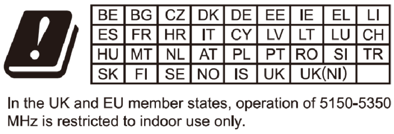
“Out of the box” Grandstream Access Points are not affected by this issue. APs with old firmware are only affected after changing into client-bridge mode. Please refer to our white paper of “WPA Security Vulnerability” here.
PRODUCT OVERVIEW
Technical Specifications
GWN7670E Technical Specifications
GWN7670E
Basic
Unit Dimension
Ø220 mm × 48.5 mm (Ø8.66″ × 1.91″)
Package Dimension
275 mm × 266 mm × 76 mm (10.83″ × 10.47″ × 2.99″)
Unit Weight
545.8 g (1.20 lb)
Package Weight
992.8 g (2.19 lb)
Installation Methods
Indoor Wall Mount, Ceiling Mount, and Junction Box Mount
Restricts access and enhances network privacy by hiding the SSID
Multicast/Broadcast Suppression
Yes
Multicast Enhancement
Converts multicast data into unicast data for transmission
Bandwidth Limiting
Supports rate limiting based on SSID, Client, MAC, or IP address
Band Steering
Yes
Client Steering
Yes
RRM
Dynamic assignment of radio power and channels
VPN
L2TPv3
VLAN
• Supports VLAN binding based on Interface, SSID, or MAC address
• Supports Management VLAN and Dynamic VLAN
Time Policy
• Tracks the time that the client connects to Wi-Fi
• Supports setting the amount of time for the client to connect to Wi-Fi and the reconnection type after a timeout
Schedule
Supports SSID, LED, and Reboot scheduling
WLAN Extension
Bridge
Yes
Extender
Yes
Mesh
2.4 GHz, 2.4 GHz & 5 GHz, 5 GHz
Hotspot 2.0
Yes
Wireless Roaming
• 802.11k, 802.11v, 802.11r
• Layer 2 roaming
Network
IPv4
Static IP or DHCP assignment
IPv6
Static IP or DHCP assignment
DHCP
Supports Server, Client, and Relay modes
NAT
NAT Pool
LLDP
Link Layer Discovery Protocol for automated device identification
User Authentication
802.1x Authentication
Yes
MAC Authentication
RADIUS-based access control using client MAC addresses as credentials
PPSK
• PPSK with or without RADIUS
• Easy PSK
Captive Portal
Supports RADIUS, Social Login, Vouchers, Password, SAML SSO, and Active Directory authentication
Security and Maintenance
Encryption
• Open System
• OSEN
• WPA2-PSK (Personal)
• WPA2-802.1x (Enterprise)
• WPA3-SAE (Personal)
• WPA3-802.1x (Enterprise)
• WPA3-OWE (Enhanced Open)
• WPA/WPA2, WPA2/WPA3
• Unique Security Certificate and Random Default Password per Device
Firmware Security
• Anti-Hacking Secure Boot
• Critical Data and Control Lockdown via Digital Signatures
Forwarding Security
• MAC Filtering
• Client Isolation
• OS Filtering
WIDS
• Inbound/Outbound Traffic Rules
• Rogue AP Detection and Containment
• ARP Attack Defense
• ND Attack Defense
Management Protocol
• TR-069
• SNMP
Service Quality
QoS
802.11e/WMM, 802.1p, 802.1q, TOS
Management Platform
Local Management
Local Web UI: Embedded controller which can manage up to 50 local GWN APs
Cloud Management
• GDMS Networking: A free cloud management platform for unlimited GWN APs
• GWN Manager: Premise-based software controller for up to 50,000 GWN APs
• GWN App: Integrates GDMS Networking and GWN Manager to manage GWN APs via the app
Package Contents
GWN7670E
Standard Items
Primary Unit
1 × GWN7670E Wi-Fi 7 Wireless AP
Manual and License
1 × Quick Installation Guide
1 × Regulatory Paper
Installation Accessories
1 × Mounting Bracket
1 × Ceiling Mounting Bracket
3 × Plastic Expansions Bolts
3 × Pan Head Tapping Screws (ST3.5 × 20 mm)
3 × Pan Head Machine Screws (M3 × 50 mm)
3 × M3 Nuts
GWN7660EM Technical Specifications
Hardware Specifications
Radio
Antenna
1 single frequency antenna and 2 dual frequency antennas
2.4GHz x 2, maximum gain 2.5 dBi
5GHz x 3, maximum gain 2.5 dBi
MIMO
2.4GHz: 2×2:2, MU-MIMO
5GHz: 3×3:2, MU-MIMO
Frequency Bands
2.4GHz Radio: 2400 – 2483.5 MHz
5GHz Radio: 5150 – 5895 MHz
(*Not all frequency bands can be used in all regions)
Channel Bandwidth
2.4G: 20 and 40 MHz
5G: 20, 40, 80 and 160 MHz
Wi-Fi Data Rates
2.4G
IEEE 802.11ax: 7.3 Mbps to 573.5 Mbps
IEEE 802.11n: 6.5 Mbps to 300 Mbps
IEEE 802.11g: 6, 9, 12, 18, 24, 36, 48, 54 Mbps
IEEE 802.11b: 1, 2, 5.5, 11 Mbps
5G
IEEE 802.11ax: 7.3 Mbps to 2402 Mbps
IEEE 802.11ac: 6.5 Mbps to 867 Mbps
IEEE 802.11n: 6.5 Mbps to 600 Mbps
IEEE 802.11a: 6, 9, 12, 18, 24, 36, 48, 54 Mbps
*Actual throughput may vary depending on many factors including environmental conditions, distance between devices, radio interference in the operating environment and mix of devices in the network.
Maximum TX Power
2.4G: 26 dBm
5G: 24 dBm
(*Maximum power varies by country, frequency band and MCS rate)
Restrict access and improve wireless network security by SSID hiding
Multicast/Broadcast Suppression
Multicast/Broadcast enable optimization with ARP proxy
Multicast Enhancement
Convert multicast data into unicast data for transmission
Bandwidth Limiting
Support SSID/Client/MAC/IP-based rate limiting
Band Steering/Client Steering
Guide client to the frequency band with more abundant spectrum resources
RRM
Dynamically assign radio power, channel
VPN
L2TPv3
VLAN
Support interface/SSID/MAC binding VLAN based Management VLAN
Dynamic VLAN
Time Policy
Track the time that the client connects to Wi-Fi, Support setting the amount of time for the client to connect to Wi-Fi and the reconnec type after a timeout
Schedule
Supports SSID, LED, Reboot schedule
WLAN Extension
Bridge
Supported
Mesh
2.4G, 2.4G & 5G, 5G
Support mesh with supported routers e.g. GWN7062E(T) by SYNC key
Support mesh with GWN76xx series
Hotspot 2.0
Supported
Wireless Roaming
802.11k, 802.11v, 802.11r
Layer 2 roaming
Network
IPv4
Static or DHCP
IPv6
Static or DHCP
DHCP
Support server/client/relay
NAT
NAT Pool
LLDP
Link Layer Discovery Protocol, discovering and identifying other LLDP enabled devices and neighboring devices in the network
User Authentication
802.1x authentication
Supported
MAC authentication
Use client MAC address as the username and password for access control through the RADIUS server
PPSK
PPSK with/without RADIUS
Captive Portal
Support radius/social login/vouchers/password/SAML SSO/active directory authentication
Security
Encryption
Open system
OSEN
WPA2-PSK (personal)
WPA2-802.1x (enterprise)
WPA3-SAE (personal)
WPA3-802.1x (enterprise)
WPA/WPA2, WPA2/WPA3
Anti-hacking secure boot and critical data/control lockdown via digital signatures, unique security certificate and random default password per device
Forwarding Security
MAC filtering
Client isolation
OS filtering
WIDS
Inbound/outbound traffic rules
Rogue AP detection and containment
ARP attack defense
ND attack defense
Service Quality
QoS
802.11e/WMM,802.1p, 802.1q, TOS
Management Platform
Local Web
Embedded controller can manage up to 50 local GWN APs
GDMS Networking
A free cloud management platform for unlimited GWN APs
GWN Manager
premise-based software controller for up to 3,000 GWN APs (Note: it depends on the hardware capacity)
GWN APP
Integrate GDMS Networking and GWN Manager to manage GWN APs via the APP
Management Protocol
TR-069
SNMP
GWN7660EM Software Specifications
GWN7605CLR Technical Specifications
Hardware Specifications
Radio
Antenna
2 dual band internal antennas 2.4GHz, gain 4.0dBi 5GHz, gain 4.0dBi
MIMO
2.4GHz: 2×2:2, MIMO 5GHz: 2×2:2, MU-MIMO
Frequency Bands
2.4GHz Radio: 2400 – 2483.5 MHz 5GHz Radio: 5150 – 5850 MHz *Not all frequency bands can be used in all regions
Channel Bandwidth
2.4G: 20 and 40MHz 5G: 20, 40 and 80MHz
Wi-Fi Data Rates
IEEE 802.11ac: 6.5 Mbps to 867 Mbps IEEE 802.11a: 6, 9, 12, 18, 24, 36, 48, 54 Mbps IEEE 802.11n: 6.5 Mbps to 300Mbps; 400 Mbps with 256-QAM on 2.4G IEEE 802.11b: 1, 2, 5.5, 11 Mbps IEEE 802.11g: 6, 9, 12, 18, 24, 36, 48, 54 Mbps *Actual throughput may vary depending on many factors including environmental conditions, distance between devices, radio interfe- rence in the operating environment and mix of devices in the network
Maximum TX Power
2.4G: 24dBm 5G: 22dBm *Maximum power varies by country, frequency band and MCS rate
anti-hacking secure boot and critical data/control lockdown via digital signatures, unique security certificate and random default password per device
Forwarding Security
MAC filtering Client isolation OS filtering
WIDS
Inbound/outbound traffic rules Rogue AP detection and containment ARP attack defense ND attack defense
Service Quality
QoS
802.11e/WMM,802.1p, 802.1q, TOS
Management Platform
Local Web
Embedded controller can manage up to 50 local GWN APs
GDMS Networking
A free cloud management platform for unlimited GWN APs
GWN Manager
premise-based software controller for up to 3,000 GWN APs
GWN APP
Integrate GDMS Networking and GWN Manager to manage GWN APs via the APP
Management Protocol
TR-069 SNMP
GWN7674 Technical Specifications
Hardware Specifications
Radio
Antenna
12 single built-in antennas 2.4GHz x 2, gain 4.5dBi 5GHz x 4, gain 5.5dBi 6GHz x 4, gain 6.0dBi BT x 1, gain 4.5dBi Scanning x 1, gain 2.4G:4.5dBi/ 5G:5.5dBi
(*Not all frequency bands can be used in all regions)
Channel Bandwidth
2.4G: 20 and 40MHz 5G: 20, 40, 80, 160 and 240MHz 6G: 20, 40, 80, 160 and 320MHz
Wi-Fi Data Rates
6G: IEEE 802.11be: Up to 11529 Mbps IEEE 802.11ax: 8 Mbps to 9608 Mbps
5G
IEEE 802.11be: Up to 8647 Mbps
IEEE 802.11ax: 7.3 Mbps to 4804 Mbps IEEE 802.11ac: 6.5 Mbps to 3466 Mbps IEEE 802.11n: 6.5 Mbps to 1200 Mbps
IEEE 802.11a: 6, 9, 12, 18, 24, 36, 48, 54 Mbps
2.4G
IEEE 802.11be: Up to 688 Mbps
IEEE 802.11ax: 7.3Mbps to 574 Mbps
IEEE 802.11n: 6.5Mbps to 300Mbps
IEEE 802.11b: 1, 2, 5.5, 11 Mbps
IEEE 802.11g: 6, 9, 12, 18, 24, 36, 48, 54 Mbps
*Actual throughput may vary depending on many factors including environmental conditions, distance between devices, radio interference in the operating environment and mix of devices in the network.
Maximum TX Power
2.4G: 27 dBm
5G: 27 dBm
6G: 25dBm
(*Maximum power varies by country, frequency band and MCS rate)
48 SSIDs total, 16 per radio (2.4GHz & 5GHz & 6GHz)
Concurrent Clients
768
Basics
Beamforming
OFDMA
Multi-RU
Preamble puncturing
4096-QAM
Multilink operation (MLO)
Target wake time (TWT)
Maximal Ratio Combining (MRC)
Space-Time Block Coding (STBC)
Low-density Parity-Check (LDPC)
802.11 Dynamic Frequency Selection (DFS)
BSS coloring
SSID Hidden
Restrict access and improve wireless network security by SSID hiding
Port Aggregation
Multiple uplink ports for port aggregation to increase uplink bandwidth
Multicast/Broadcast Suppression
Multicast/Broadcast enable optimization with ARP proxy
Multicast Enhancement
Convert multicast data into unicast data for transmission
Bandwidth Limiting
Support SSID/Client/MAC/IP-based rate limiting
Band Steering/Client Steering
Guide client to the frequency band with more abundant spectrum resources
RRM
Dynamically assign radio power, channel
VPN
L2TPv3
VLAN
Support interface/SSID/MAC binding VLAN based Management VLAN
Dynamic VLAN
Time Policy
Track the time that the client connects to Wi-Fi, Support setting the amount of time for the client to connect to Wi-Fi and the reconnec type after a timeout
Schedule
Supports SSID, LED, Reboot schedule
WLAN Extension
Bridge
Supported
Extender
Supported
Mesh
2.4GHz, 5GHz, 2.4GHz & 5GHz, 5GHz & 6GHz
Hotspot 2.0
Supported
Wireless Roaming
802.11k, 802.11v, 802.11r
Layer 2 roaming
Network
IPv4
Static or DHCP
IPv6
Static or DHCP
DHCP
Support server/client/relay
NAT
NAT Pool
LLDP
Link Layer Discovery Protocol, discovering and identifying other LLDP enabled devices and neighboring devices in the network
User Authentication
802.1x authentication
Supported
MAC authentication
Use client MAC address as the username and password for access control through the RADIUS server
PPSK
PPSK with/without RADIUS
Captive Portal
Support radius/social login/vouchers/password/SAML SSO/active directory authentication
Security
Encryption
Open system
OSEN
WPA2-PSK (personal)
WPA2-802.1x (enterprise)
WPA3-SAE (personal)
WPA3-802.1x (enterprise)
WPA/WPA2, WPA2/WPA3
Anti-hacking secure boot and critical data/control lockdown via digital signatures, unique security certificate and random default password per device
Forwarding Security
MAC filtering
Client isolation
OS filtering
WIDS
Inbound/outbound traffic rules
Rogue AP detection and containment
ARP attack defense
ND attack defense
Service Quality
QoS
802.11e/WMM,802.1p, 802.1q, TOS
Management Platform
Local Web
Embedded controller can manage up to 50 local GWN APs
GDMS Networking
A free cloud management platform for unlimited GWN APs
GWN Manager
premise-based software controller for up to 3,000 GWN APs (Note: it depends on the hardware capacity)
GWN APP
Integrate GDMS Networking and GWN Manager to manage GWN APs via the APP
Management Protocol
TR-069
SNMP
GWN7674 Software Specifications
GWN7670LR Technical Specifications
Hardware Specifications
Radio
Antenna
2.4G: Directional internal 8dBi/External omni 3.5dBi
5G: Directional internal 13.5dBi/External omni 3.5dBi
BT: 5.0dBi
Directional internal antenna beamwidth
2.4G: 90 degree
5G: 35 degree
MIMO
2.4GHz: 2×2:2, MIMO
5GHz: 2×2:2, MIMO
Frequency Bands
2.4GHz Radio: 2400 – 2483.5 MHz
5GHz Radio: 5150 – 5895 MHz
(*Not all frequency bands can be used in all regions)
Channel Bandwidth
2.4G: 20 and 40 MHz
5G: 20, 40, 80 and 160 MHz
Wi-Fi Data Rates
5G
IEEE 802.11be: Up to 2882 Mbps
IEEE 802.11ax: 7.3 Mbps to 2402 Mbps IEEE 802.11ac: 6.5 Mbps to 1732 Mbps IEEE 802.11n: 6.5 Mbps to 600 Mbps
IEEE 802.11a: 6, 9, 12, 18, 24, 36, 48, 54 Mbps
2.4G
IEEE 802.11be: Up to 688 Mbps
IEEE 802.11ax: 7.3Mbps to 574 Mbps
IEEE 802.11n: 6.5Mbps to 300Mbps
IEEE 802.11b: 1, 2, 5.5, 11 Mbps
IEEE 802.11g: 6, 9, 12, 18, 24, 36, 48, 54 Mbps
*Actual throughput may vary depending on many factors including environmental conditions, distance between devices, radio interference in the operating environment and mix of devices in the network.
Maximum TX Power
2.4G: 27 dBm
5G: 26 dBm
(*Maximum power varies by country, frequency band and MCS rate)
Restrict access and improve wireless network security by SSID hiding
Port Aggregation
Multiple uplink ports for port aggregation to increase uplink bandwidth
Multicast/Broadcast Suppression
Multicast/Broadcast enable optimization with ARP proxy
Multicast Enhancement
Convert multicast data into unicast data for transmission
Bandwidth Limiting
Support SSID/Client/MAC/IP-based rate limiting
Band Steering/Client Steering
Guide client to the frequency band with more abundant spectrum resources
RRM
Dynamically assign radio power, channel
VPN
L2TPv3
VLAN
Support interface/SSID/MAC binding VLAN based Management VLAN
Dynamic VLAN
Time Policy
Track the time that the client connects to Wi-Fi, Support setting the amount of time for the client to connect to Wi-Fi and the reconnec type after a timeout
Schedule
Supports SSID, LED, Reboot schedule
WLAN Extension
Bridge
Supported
Mesh
2.4G, 2.4G & 5G, 5G
Hotspot 2.0
Supported
Wireless Roaming
802.11k, 802.11v, 802.11r
Layer 2 roaming
Network
IPv4
Static or DHCP
IPv6
Static or DHCP
DHCP
Support server/client/relay
NAT
NAT Pool
LLDP
Link Layer Discovery Protocol, discovering and identifying other LLDP enabled devices and neighboring devices in the network
User Authentication
802.1x authentication
Supported
MAC authentication
Use client MAC address as the username and password for access control through the RADIUS server
PPSK
PPSK with/without RADIUS
Captive Portal
Support radius/social login/vouchers/password/SAML SSO/active directory authentication
Security
Encryption
Open system
OSEN
WPA2-PSK (personal)
WPA2-802.1x (enterprise)
WPA3-SAE (personal)
WPA3-802.1x (enterprise)
WPA/WPA2, WPA2/WPA3
Anti-hacking secure boot and critical data/control lockdown via digital signatures, unique security certificate and random default password per device
Forwarding Security
MAC filtering
Client isolation
OS filtering
WIDS
Inbound/outbound traffic rules
Rogue AP detection and containment
ARP attack defense
ND attack defense
Service Quality
QoS
802.11e/WMM,802.1p, 802.1q, TOS
Management Platform
Local Web
Embedded controller can manage up to 50 local GWN APs
GDMS Networking
A free cloud management platform for unlimited GWN APs
GWN Manager
premise-based software controller for up to 3,000 GWN APs
GWN APP
Integrate GDMS Networking and GWN Manager to manage GWN APs via the APP
Management Protocol
TR-069
SNMP
GWN7670LR Software Specifications
GWN7672 Technical Specifications
Wi-Fi Standards
IEEE 802.11 a/b/g/n/ac/ax/be
Antennas
7 single frequency antennas
2.4GHz x 2, gain 3.5dBi
5GHz x 2, gain 5.5dBi
6GHz x 2, gain 5.5dBi
BT gain 3.5dBi
Wi-Fi Data Rates
2.4GHz:
IEEE 802.11be: Up to 688 Mbps
IEEE 802.11ax: 7.3 Mbps to 574 Mbps IEEE
IEEE 802.11n: 6.5Mbps to 300Mbps
IEEE 802.11b: 1, 2, 5.5, 11 Mbps
IEEE 802.11g: 6, 9, 12, 18, 24, 36, 48, 54 Mbps
5GHz:
IEEE 802.11be: Up to 4320 Mbps
IEEE 802.11ax: 7.3 Mbps to 2402 Mbps
IEEE 802.11ac: 6.5 Mbps to 1732 Mbps
IEEE 802.11n: 6.5Mbps to 600Mbps
IEEE 802.11a: 6, 9, 12, 18, 24, 36, 48, 54 Mbps
*Actual throughput may vary depending on many factors including environmental conditions, distance between devices, radio
interference in the operating environment and mix of devices in the network
Frequency Bands
2.4GHz Radio: 2400 – 2483.5 MHz
5GHz Radio: 5150 – 5850 MHz
6GHz Radio: 5945 – 7125 MHz
*Not all frequency bands can be used in all regions
Channel Bandwidth
2.4G: 20 and 40 MHz
5G: 20, 40 , 80 , 160MHz and 240MHz
6G: 20, 40 , 80, 160 and 320MHz
Wi-Fi and System Security
WEP, WPA/WPA2-PSK, WPA/WPA2 Enterprise (TKIP/AES); WPA3, anti-hacking secure boot and critical data/control lockdown via digital signatures, unique security certificate and random default password per device
MIMO
2×2:2 2.4GHz
2×2:2 5GHz
2×2:2 6GHz
Coverage Range
Up to 175 meters
*coverage range can vary based on the environment
Maximum TX Power
2.4G: 26dBm
5G: 25dBm
6G: 24dBm
*Maximum power varies by country, frequency band, and MCS rate
48 SSIDs total, 16 per radio (2.4GHz, 5GHz, and 6GHz)
Concurrent Clients
384
Network Interfaces
2x 5G Ethernet RJ45 ports
Auxiliary Ports
1x Reset Pinhole, 1x Kensington lock
Bluetooth®
Bluetooth Low Energy 5.3
Mounting
Indoor wall mount or ceiling mount, kits included
LEDs
1 tri-color LED for device tracking and status indication
Network Protocols
IPv4, IPv6, 802.1Q, 802.1p, 802.1x, 802.11e/WMM
QoS
802.11e/WMM, VLAN, TOS
Network Management
Embedded controller can manage up to 50 local GWN APs GDMS Networking offers a free cloud management platform for unlimited GWN APs. GWN Manager offers premise-based software controller for up to 50,000 GWN APs.
Auto Power Saving
Self-power adaptation upon auto detection of PoE or PoE+
Power and Green Energy Efficiency
PoE+ 802.3at
Maximum Power Consumption: 25W
Environmental
Operation: 0°Cto 45°C Storage: -30°C to 60°C Humidity: 10% to 90% Non-condensing
Physical
Unit Dimension: 220mmx220mmx54mm; Unit Weight: 838.4g Entire Package Dimension: 275mmx266mmx76mm; Entire Package Weight: 1271.4g
5G: IEEE 802.11be: Up to 2882 Mbps IEEE 802.11ax: 7.3 Mbps to 2402 Mbps IEEE 802.11ac: 6.5 Mbps to 1732 Mbps IEEE 802.11n: 6.5 Mbps to 300 Mbps IEEE 802.11a: 6, 9, 12, 18, 24, 36, 48, 54 Mbps
2.4G: IEEE 802.11be: Up to 688 Mbps IEEE 802.11ax: 7.3 Mbps to 574 Mbps IEEE 802.11n: 6.5Mbps to 300Mbps IEEE 802.11b: 1, 2, 5.5, 11 Mbps IEEE 802.11g: 6, 9, 12, 18, 24, 36, 48, 54 Mbps
Note: Actual throughput may vary depending on many factors including environmental conditions, distance between devices, radio interfe- rence in the operating environment and mix of devices in the network.
Frequency Bands
2.4GHz Radio: 2400 – 2483.5 MHz
5GHz Radio: 5180 – 5895 MHz
Note: Not all frequency bands can be used in all regions.
Channel Bandwidth
2.4G: 20 and 40 MHz
5G: 20, 40, 80, 160 MHz
Wi-Fi and System Security
WEP, WPA/WPA2-PSK, WPA/WPA2 Enterprise (TKIP/AES); WPA3, anti-hacking secure boot and critical data/control lockdown via digital signatures, unique security certificate and random default password per device.
MIMO
2×2:2 2.4GHz
2×2:2 5GHz
Coverage Range
Up to 175 meters
Note: coverage range can vary based on environment.
Max TX Power
2.4G: 26dBm
5G: 26dBm
Note: Maximum power varies by country, frequency band and MCS rate.
1 tri-color LED for device tracking and status indication
Network Protocols
IPv4, IPv6, 802.1Q, 802.1p, 802.1x, 802.11e/WMM
QoS
802.11e/WMM, VLAN, TOS
Network Management
Embedded controller can manage up to 50 local GWN APs GDMS Networking offers a free cloud management platform for unlimited GWN APs. GWN Manager offers premise-based software controller for up to 50,000 GWN APs.
Power and Green Energy Efficiency
PoE/PoE+ 802.3af/at; Maximum Power Consumption: 15.5W
Environment
Operating: 0°C to 45°C
Storage: -30°C to 60°C
Humidity: 10–90% non-condensing
Physical
Unit Dimension: 150mmx106mmx34.1mm; Unit Weight: 473g Entire Package Dimension: 193mmx138.5mmx54mm; Entire Package Weight: 600g
IEEE 802.11ax: 7.3 Mbps to 2402 Mbps IEEE 802.11ac: 6.5 Mbps to 1732 Mbps IEEE 802.11n: 6.5Mbps to 600Mbps IEEE 802.11a: 6, 9, 12, 18, 24, 36, 48, 54 Mbps *Actual throughput may vary depending on many factors including environmental conditions, distance between devices, radio interference in the operating environment and mix of devices in the network
Frequency Bands
2.4GHz Radio: 2400 – 2483.5 MHz 5GHz Radio: 5180 – 5895 MHz *Not all frequency bands can be used in all regions
Channel Bandwidth
2.4G: 20 and 40 MHz 5G: 20, 40 , 80 and 160MHz
Wi-Fi and System Security
WEP, WPA/WPA2-PSK, WPA/WPA2 Enterprise (TKIP/AES); WPA3, anti-hacking secure boot and critical data/control lockdown via digital signatures, unique security certificate and random default password per device
MIMO
2×2:2 2.4GHz
2×2:2 5GHz
Coverage Range
Up to 175 meters
*coverage range can vary based on the environment
Maximum TX Power
5G: 25dBm 2.4G: 27dBm *Maximum power varies by country, frequency band, and MCS rate
1 tri-color LEDs for device tracking and status indication
Network Protocols
IPv4, IPv6, 802.1Q, 802.1p, 802.1x, 802.11e/WMM
QoS
802.11e/WMM, VLAN, TOS
Network Management
Embedded controller can manage up to 50 local GWN APs GDMS Networking offers a free cloud management platform for unlimited GWN APs. GWN Manager offers premise-based software controller for up to 50,000 GWN APs.
Auto Power Saving
Self-power adaptation upon auto detection of PoE or PoE+
Power and Green Energy Efficiency
Supports 802.3az PoE 802.3af/ 802.3at; Maximum Power Consumption: 15.5W
Environmental
Operation: 0°Cto 45°C Storage: -30°C to 60°C Humidity: 10% to 90% Non-condensing
Physical
Unit Dimension: 185mmx185mmx44.5mm; Unit Weight: 527g
2 x dual-band internal antennas,1x 5G internal antenna Antenna1, 2.4G gain 3.0dBi, 5G gain 3.5dBi Antenna2, 2.4G gain 3.5dBi, 5G gain 3.0dBi 5G Antenna, gain 4.5dBi
*Actual throughput may vary depending on many factors including environmental conditions, distance between devices, radio interference in the operating environment and mix of devices in the network
Frequency Bands
2.4 GHz Radio: 2412 – 2483.5 MHz 5GHz Radio: 5150 – 5895 MHz *Not all frequency bands can be used in all regions. The band 5150-5350 MHz is restricted to indoor use only in all EU states
Channel Bandwidth
2.4G: 20 and 40 MHz 5G: 20, 40, 80 MHz and 160 MHz
Wi-Fi and System Security
WEP, WPA/WPA2-PSK, WPA/WPA2 Enterprise (TKIP/AES); WPA3, anti-hacking secure boot and critical data/control lockdown via digital signatures, unique security certificate and random default password per device
MU-MIMO
2×2:2 2.4GHz 3×3:2 5GHz
Coverage Range
Up to 100 meters
*coverage range can vary based on environment
Maximum TX Power
5G: 26dBm 2.4G: 24dBm *Maximum power varies by country, frequency band and MCS rate
1x 10/100/1000M uplink Ethernet port with PoE/PoE+ 2x 10/100/1000M Ethernet port with PSE 1x 10/100/1000M Ethernet port
Auxiliary Ports
1x Reset Pinhole, 1x Kensington lock
Mounting
Indoor wall mount, kits included
LEDs
1 tri-color LEDs for device tracking and status indication
Network Protocols
IPv4, IPv6, 802.1Q, 802.1p, 802.1x, 802.11e/WMM
QoS
802.11e/WMM, VLAN, TOS
Network Management
Embedded controller can manage up to 50 local GWN APs GDMS Networking offers a free cloud management platform for unlimited GWN APs. GWN Manager offers premise-based software controller for up to 50,000 APs.
Power and Green Energy Efficiency
PoE 802.3af/ 802.3at PSE max output: Total 12W power budget for LAN2/LAN3 Maximum Power Consumption: 7.5W (Excluding PoE Output)
Environmental
Operation: 0°C to 45°C Storage: -10°C to 60°C Humidity: 10% to 90% Non-condensing
Physical
Unit Dimension: 135 x 115 x 30mm; Unit Weight: 253g Entire Package Dimension: 171 x 140 x 33mm; Entire Package Weight: 358g
2x dual-band internal antennas,1x 5G internal antenna Antenna1, 2.4G gain 3.0dBi, 5G gain 5.0dBi Antenna2, 2.4G gain 2.5dBi, 5G gain 4.5dBi 5G Antenna gain 4.5dBi
IEEE 802.11ac: 6.5 Mbps to 1732 Mbps IEEE 802.11n: 6.5Mbps to 300Mbps IEEE 802.11a: 6, 9, 12, 18, 24, 36, 48, 54 Mbps *Actual throughput may vary depending on many factors including environmental conditions, distance between devices, radio interference in the operating environment and mix of devices in the network
Frequency Bands
2.4GHz Radio: 2412 – 2484 MHz 5GHz Radio: 5150 – 5895 MHz *Not all frequency bands can be used in all regions
Channel Bandwidth
2.4G: 20 and 40 MHz 5G: 20, 40, 80 MHz and 160 MHz
Wi-Fi and System Security
WEP, WPA/WPA2-PSK, WPA/WPA2 Enterprise (TKIP/AES); WPA3, anti-hacking secure boot and critical data/control lockdown via digital signatures, unique security certificate and random default password per device
MIMO
2×2:2 2.4GHz 3×3:2 5GHz
Coverage Range
Up to 100 meters
*coverage range can vary based on environment
Maximum TX Power
5G: 26dBm 2.4G: 24dBm *Maximum power varies by country, frequency band and MCS rate
1x 10/100/1000M uplink Ethernet port with PoE/PoE+ 2x 10/100/1000M Ethernet port with PSE 1x 10/100/1000M Ethernet port
Auxiliary Ports
1x Reset Pinhole, 1x Kensington lock
Mounting
In-wall mountable
LEDs
1 tri-color LEDs for device tracking and status indication
Network Protocols
IPv4, IPv6, 802.1Q, 802.1p, 802.1x, 802.11e/WMM
QoS
802.11e/WMM, VLAN, TOS
Network Management
Embedded controller can manage up to 50 local GWN APs GDMS Networking offers a free cloud management platform for unlimited GWN APs. GWN Manager offers premise-based software controller for up to 50,000 APs.
Auto Power Saving
Self-power adaptation upon auto detection of PoE or PoE+
Power and Green Energy Efficiency
Support 802.3az PoE 802.3af/ 802.3at; PSE Maximum Output Per Port: 6W; Maximum Power Consumption: 25W
Environmental
Operation: 0°C to 45°C Storage: -30°C to 60°C Humidity: 5% to 95% Non-condensing
Physical
Unit Dimension: 135mm(L) x 86mm(W) x 38.5mm(H); Unit Weight: 241g Entire Package Dimension: 176mm(L) x 118.5mm(W) x 65mm(H); Entire Package Weight: 361g
2.4G: IEEE 802.11ax: 7.3 Mbps to 1147 Mbps IEEE 802.11n: 6.5 Mbps to 600 Mbps IEEE 802.11b: 1, 2, 5.5, 11 Mbps IEEE 802.11g: 6, 9, 12, 18, 24, 36, 48, 54 Mbps *Actual throughput may vary depending on many factors including environmental conditions, distance between devices, radio interference in the operating environment and mix of devices in the network.
Frequency Bands
2.4GHz radio: 2400 – 2483.5 MHz 5GHz radio: 5150-5850 MHz *Not all frequency bands can be used in all regions.
Channel Bandwidth
2.4G: 20 and 40 MHz (x4) 5G: 20, 40,80 and 160 MHz (x4)
Wi-Fi and System Security
WPA/WPA2-PSK, WPA/WPA2 Enterprise (TKIP/AES); WPA3, anti-hacking secure boot and critical data/control lockdown via digital signatures, unique security certificate and random default password per device.
MU-MIMO
4×4:4 2.4GHz
4×4:4 5GHz
Coverage Range
Up to 300 meters
*coverage range can vary based on the environment
Maximum TX Power
2.4G: 24.5dBm
5G: 23.5dBm *Maximum power varies by country, frequency band, and MCS rate.
Wall mount or pole mount, kits included (The mounting kits can be rotated and adjusted by 60°).
LEDs
1 tri-color LEDs for device tracking and status indication, 1 single-color LED for SFP indication.
Network Protocols
IPv4, IPv6, 802.1Q, 802.1p, 802.1x, 802.11e/WMM
QoS
802.11e/WMM, VLAN, TOS
Network Management
Embedded controller can manage up to 50 local GWN APs GDMS Networking offers a free cloud management platform for unlimited GWN APs. GWN Manager offers premise-based software controller for up to 3,000 GWN APs.
Power and Green Energy Efficiency
PoE 802.3at; Maximum Power Consumption: 24W
Environmental
Operation: -30°Cto 60°C Storage: -30°C to 60°C Humidity: 10% to 90% Non-condensing
Physical
Unit Dimension: 260mm(L)x310mm(W)x59mm(H); Unit Weight: 1.445kg Entire Package Dimension: 469mm x 377mm x 137mm; Entire Package Weight: 3.06kg
2.4G: IEEE 802.11ax: 7.3 Mbps to 1147 Mbps; IEEE 802.11n: 6.5Mbps to 600Mbps; IEEE 802.11b: 1, 2, 5.5, 11 Mbps; IEEE 802.11g: 6, 9, 12, 18, 24, 36, 48, 54 Mbps *Actual throughput may vary depending on many factors including environmental conditions, distance between devices, radio interference in the operating environment and mix of devices in the network.
*Not all frequency bands can be used in all regions
Channel Bandwidth
2.4G: 20 and 40 MHz 5G: 20, 40 , 80 and 160MHz
Wi-Fi and System Security
WPA/WPA2-PSK, WPA/WPA2 Enterprise (TKIP/AES); WPA3, anti-hacking secure boot and critical data/control lockdown via digital signatures, unique security certificate and random default password per device.
MU-MIMO
4×4:4 2.4GHz
4×4:4 5GHz
Coverage Range
Up to 175 meters
*coverage range can vary based on the environment
Maximum TX Power
2.4G: 26.5dBm
5G: 25.5dBm *Maximum power varies by country, frequency band, and MCS rate.
3 tri-color LEDs for device tracking and status indication
Network Protocols
IPv4, IPv6, 802.1Q, 802.1p, 802.1x, 802.11e/WMM
QoS
802.11e/WMM, VLAN, TOS
Network Management
Embedded controller can manage up to 50 local GWN APs GDMS Networking offers a free cloud management platform for unlimited GWN APs. GWN Manager offers premise-based software controller for up to 3,000 GWN APs.
Power and Green Energy Efficiency
PoE 802.3at; Maximum Power Consumption: 21W
Environmental
Operation: 0°Cto 50°C Storage: -10°C to 60°C Humidity: 10% to 95% Non-condensing
Physical
Unit Dimension: 205.3mmx205.3mmx45.9mm; Unit Weight: 0.714Kg Entire Package Dimension: 258mmx247mmx86mm; Entire Package Weight: 1.06Kg
2.4G: IEEE 802.11ax: 7.3 Mbps to 573.5 Mbps IEEE 802.11n: 6.5 Mbps to 300 Mbps IEEE 802.11b: 1, 2, 5.5, 11 Mbps IEEE 802.11g: 6, 9, 12, 18, 24, 36, 48, 54 Mbps *Actual throughput may vary depending on many factors including environmental conditions, distance between devices, radio interference in the operating environment and mix of devices in the network
*Not all frequency bands can be used in all regions
Channel Bandwidth
2.4G: 20 and 40 MHz 5G: 20, 40 , 80 and 160MHz
Wi-Fi and System Security
WEP, WPA/WPA2-PSK, WPA/WPA2 Enterprise (TKIP/AES); WPA3, anti-hacking secure boot and critical data/control lockdown via digital signatures, unique security certificate and random default password per device.
MIMO
2×2:2 2.4GHz (MU-MIMO)
2×2:2 5GHz (MU-MIMO)
Coverage Range
Up to 300 meters
*coverage range can vary based on the environment
Maximum TX Power
2.4G: 27dBm
5G: 26dBm *Maximum power varies by country, frequency band, and MCS rate
1 tri-color LED for device tracking and status indication; 1 single-color LED for SFP
Network Protocols
IPv4, IPv6, 802.1Q, 802.1p, 802.1x, 802.11e/WMM
QoS
802.11e/WMM, VLAN, TOS
Network Management
Embedded controller can manage up to 50 local GWN APs GDMS Networking offers a free cloud management platform for unlimited GWN APs. GWN Manager offers premise-based software controller for up to 3,000 GWN APs.
Auto Power Saving
Self-power adaptation upon auto detection of PoE or PoE+.
Power and Green Energy Efficiency
PoE 802.3af/ 802.3at; Maximum Power Consumption: 13W
Environmental
Operation: -30°Cto 60°C Storage: -30°C to 70°C Humidity: 5% to 95% Non-condensing
Physical
Unit Dimension: 270mm x 230mm x 57mm Unit (including brackets): 1kg Entire Package Dimension: 439mm x 329mm x 137mm Entire Package Weight: 2.4kg
2.4G: IEEE 802.11ax: 7.3 Mbps to 573.5 Mbps; IEEE 802.11n: 6.5Mbps to 300Mbps; IEEE 802.11b: 1, 2, 5.5, 11 Mbps; IEEE 802.11g: 6, 9, 12, 18, 24, 36, 48, 54 Mbps *Actual throughput may vary depending on many factors including environmental conditions, distance between devices, radio interference in the operating environment and mix of devices in the network
*Not all frequency bands can be used in all regions
Channel Bandwidth
2.4G: 20 and 40 MHz 5G: 20, 40 , 80 and 160MHz
Wi-Fi and System Security
WEP, WPA/WPA2-PSK, WPA/WPA2 Enterprise (TKIP/AES); WPA3, anti-hacking secure boot and critical data/control lockdown via digital signatures, unique security certificate and random default password per device.
MIMO
2×2:2 2.4GHz (MU-MIMO)
3×3:2 5GHz (MU-MIMO)
Coverage Range
Up to 175 meters
*coverage range can vary based on the environment
Maximum TX Power
2.4G: 24 dBm
5G: 24dBm *Maximum power varies by country, frequency band, and MCS rate
3 tri-color LEDs for device tracking and status indication
Network Protocols
IPv4, IPv6, 802.1Q, 802.1p, 802.1x, 802.11e/WMM
QoS
802.11e/WMM, VLAN, TOS
Network Management
Embedded controller can manage up to 50 local GWN APs GDMS Networking offers a free cloud management platform for unlimited GWN APs. GWN Manager offers premise-based software controller for up to 3,000 GWN APs.
Auto Power Saving
Self-power adaptation upon auto detection of PoE or PoE+
Power and Green Energy Efficiency
PoE 802.3af/ 802.3at; Maximum Power Consumption: 12.95W
Environmental
Operation: 0°Cto 50°C Storage: -10°C to 60°C Humidity: 10% to 95% Non-condensing
Physical
Unit Dimension: 180.4mmx180.4mmx40.8mm(TBD); Unit Weight: 385g Entire Package Dimension: 228.5x220x79mm(TBD); Entire Package Weight: 630g
IEEE 802.11ax: 7.3 Mbps to 2403 Mbps IEEE 802.11ac: 6.5 Mbps to 1734 Mbps IEEE 802.11n: 6.5Mbps to 300Mbps IEEE 802.11a: 6, 9, 12, 18, 24, 36, 48, 54 Mbps *Actual throughput may vary depending on many factors including environmental conditions, distance between devices, radio interference in the operating environment and mix of devices in the network
6GHz Radio: 5945 -7125MHz *Not all frequency bands can be used in all regions
Channel Bandwidth
2.4G: 20 and 40 MHz 5G: 20, 40 , 80 and 160MHz
6G: 20, 40 80 and 160MHz
Wi-Fi and System Security
WEP, WPA/WPA2-PSK, WPA/WPA2 Enterprise (TKIP/AES); WPA3, anti-hacking secure boot and critical data/control lockdown via digital signatures, unique security certificate and random default password per device
MIMO
2×2:2 2.4GHz (MU-MIMO)
2×2:2 5GHz (MU-MIMO)
2×2:2 6GHz
Coverage Range
Up to 175 meters
*coverage range can vary based on the environment
Maximum TX Power
2.4G: 24 dBm
5G: 27dBm 6G: 26 dBm *Maximum power varies by country, frequency band, and MCS rate
48 SSIDs total, 16 per radio (2.4GHz & 5GHz & 6GHz)
Concurrent Clients
384
Network Interfaces
1x autosensing 10/100/1000 Base-T Ethernet Port
1x autosensing 10/100/1000/2500 Base-T Ethernet Port
Auxiliary Ports
1x Reset Pinhole, 1x Kensington lock
Mounting
Indoor wall mount or ceiling mount, kits included
LEDs
3 tri-color LEDs for device tracking and status indication
Network Protocols
IPv4, IPv6, 802.1Q, 802.1p, 802.1x, 802.11e/WMM
QoS
802.11e/WMM, VLAN, TOS
Network Management
Embedded controller can manage up to 50 local GWN APs GDMS Networking offers a free cloud management platform for unlimited GWN APs. GWN Manager offers premise-based software controller for up to 3,000 GWN APs.
Auto Power Saving
Self-power adaptation upon auto detection of PoE or PoE+
Power and Green Energy Efficiency
PoE 802.3at Maximum Power Consumption: 22.55W
Environmental
Operation: 0°Cto 50°C Storage: -10°C to 60°C Humidity: 10% to 95% Non-condensing
Physical
Unit Dimension: 205.3mm(L)x205.3mm(W)x45.9mm(H); Unit Weight: 540g
IEEE 802.11ac: 6.5 Mbps to 1733 Mbps IEEE 802.11n: 6.5Mbps to 600Mbps IEEE 802.11a: 6, 9, 12, 18, 24, 36, 48, 54 Mbps *Actual throughput may vary depending on many factors including environmental conditions, distance between devices, radio interference in the operating environment and mix of devices in the network
Frequency Bands
2.4GHz Radio: 2412 – 2484 MHz 5GHz Radio: 5180 – 5825 MHz *Not all frequency bands can be used in all regions
Channel Bandwidth
2.4G: 20 and 40 MHz 5G: 20, 40 and 80 MHz
Wi-Fi and System Security
WEP, WPA/WPA2-PSK, WPA/WPA2 Enterprise (TKIP/AES); WPA3, anti-hacking secure boot and critical data/control lockdown via digital signatures, unique security certificate and random default password per device
MU-MIMO
2×2:2 2.4GHz (MIMO) 2×2:2 5GHz (MU-MIMO)
Coverage Range
Up to 100 meters
*coverage range can vary based on environment
Maximum TX Power
5G: 27dBm 2.4G: 24dBm *Maximum power varies by country, frequency band and MCS rate
1x 10/100/1000M uplink Ethernet port with PoE/PoE+ 2x 10/100/1000M Ethernet port with PSE 1x 10/100/1000M Ethernet port
Auxiliary Ports
1x Reset Pinhole
Mounting
In-wall mountable
LEDs
1 tri-color LEDs for device tracking and status indication
Network Protocols
IPv4, IPv6, 802.1Q, 802.1p, 802.1x, 802.11e/WMM
QoS
802.11e/WMM, VLAN, TOS
Network Management
Embedded controller can manage up to 50 local GWN APs GDMS Networking offers a free cloud management platform for unlimited GWN APs. GWN Manager offers premise-based software controller for up to 3,000 GWN APs.
Auto Power Saving
Self-power adaptation upon auto detection of PoE or PoE+
Power and Green Energy Efficiency
Support 802.3az PoE 802.3af/ 802.3at; PSE Maximum Output Per Port: 6W; Maximum Power Consumption: 25W
Environmental
Operation:-10°Cto 50°C Storage: -30°C to 60°C Humidity: 5% to 95% Non-condensing
Physical
Unit Dimension: 135mm(L)x86mm(W)x38.5mm(H); Unit Weight: 185g Entire Package Dimension: 176mm(L)x118.5mm(W)x65mm(H); Entire Package Weight: 400g
Package Content
GWN7661 In-Wall Wireless AP
4x Screws(KB 3.5*26)
Quick Installation Guide
Compliance
FCC, CE, RCM, IC, UKCA
GWN7661 Technical Specifications
GWN7662 Technical Specifications
Wi-Fi Standards
IEEE 802.11 a/b/g/n/ac(Wave-2)/ax
Antennas
6 single frequency internal antennas 2.4GHz, gain 3.65dBi 5 GHz, gain 5.26dBi
Wi-Fi Data Rates
5G: IEEE802.11ax:8.6Mbps to 4804Mbps IEEE 802.11ac: 6.5 Mbps to 3464 Mbps IEEE 802.11n: 6.5Mbps to 600Mbps IEEE 802.11a: 6, 9, 12, 18, 24, 36, 48, 54 Mbps
*Actual throughput may vary depending on many factors including environmental conditions, distance between devices, radio interference in the operating environment and mix of devices in the network
Frequency Bands
2.4GHz Radio: 2412 – 2484 MHz 5GHz Radio: 5180 – 5825 MHz *Not all frequency bands can be used in all regions
Channel Bandwidth
2.4G: 20 and 40 MHz 5G: 20, 40 , 80 and 160MHz
Wi-Fi and System Security
WEP, WPA/WPA2-PSK, WPA/WPA2 Enterprise (TKIP/AES); WPA3, anti-hacking secure boot and critical data/control lockdown via digital signatures, unique security certificate and random default password per device
MIMO
2×2:2 2.4GHz (MU-MIMO)
4×4:4 5GHz (MU-MIMO)
Coverage Range
Up to 175 meters
*coverage range can vary based on the environment
Maximum TX Power
2.4G: 25dBm 5G: 27dBm *Maximum power varies by country, frequency band, and MCS rate
1x autosensing 10/100/1000/2500 Base-T Ethernet Port
Auxiliary Ports
1x Reset Pinhole
Mounting
Indoor wall mount or ceiling mount, kits included
LEDs
1 tri-color LEDs for device tracking and status indication
Network Protocols
IPv4, IPv6, 802.1Q, 802.1p, 802.1x, 802.11e/WMM
QoS
802.11e/WMM, VLAN, TOS
Network Management
Embedded controller can manage up to 50 local GWN APs GDMS Networking offers a free cloud management platform for unlimited GWN APs. GWN Manager offers premise-based software controller for up to 50,000 GWN APs (based on hardware).
Auto Power Saving
Self-power adaptation upon auto detection of PoE or PoE+
Power and Green Energy Efficiency
Supports 802.3az PoE 802.3af/ 802.3at; Maximum Power Consumption: 16W
Environmental
Operation: -10°Cto 45°C Storage: -30°C to 60°C Humidity: 5% to 95% Non-condensing
Physical
Unit Dimension: 205.3mm(L)x205.3mm(W)x45.9mm(H); Unit Weight: 540g
IEEE 802.11ac: 6.5 Mbps to 1733 Mbps IEEE 802.11n: 6.5Mbps to 600Mbps IEEE 802.11a: 6, 9, 12, 18, 24, 36, 48, 54 Mbps *Actual throughput may vary depending on many factors including environmental conditions, distance between devices, radio interference in the operating environment and mix of devices in the network
Frequency Bands
2.4GHz Radio: 2412 – 2484 MHz 5GHz Radio: 5180 – 5825 MHz *Not all frequency bands can be used in all regions
Channel Bandwidth
2.4G: 20 and 40 MHz 5G: 20, 40 and 80 MHz
Wi-Fi and System Security
WEP, WPA/WPA2-PSK, WPA/WPA2 Enterprise (TKIP/AES); WPA3, anti-hacking secure boot and critical data/control lockdown via digital signatures, unique security certificate and random default password per device
MU-MIMO
2×2:2 2.4GHz (MIMO) 4×4:4 5GHz (MU-MIMO)
Coverage Range
Up to 100 meters
*coverage range can vary based on environment
Maximum TX Power
5G: 25dBm 2.4G: 23dBm *Maximum power varies by country, frequency band and MCS rate
1x 10/100/1000M uplink Ethernet port with PoE/PoE+ 2x 10/100/1000M Ethernet port with PSE 1x 10/100/1000M Ethernet port
Auxiliary Ports
1x Reset Pinhole
Mounting
In-wall mountable
LEDs
1 tri-color LEDs for device tracking and status indication
Network Protocols
IPv4, IPv6, 802.1Q, 802.1p, 802.1x, 802.11e/WMM
QoS
802.11e/WMM, VLAN, TOS
Network Management
Embedded controller can manage up to 30 local GWN APs. GDMS Networking offers a free cloud management platform for unlimited GWN APs. GWN Manager offers premise-based software controller for up to 3,000 GWN APs.
Auto Power Saving
Self-power adaptation upon auto detection of PoE or PoE+
Power and Green Energy Efficiency
Support 802.3az PoE 802.3af/ 802.3at; PSE Maximum Output Per Port: 6W; Maximum Power Consumption: 25W
Environmental
Operation:-10°Cto 50°C Storage: -30°C to 60°C Humidity: 5% to 95% Non-condensing
Physical
Unit Dimension: 135mm(L)x86mm(W)x38.5mm(H) Entire Package Dimension: 176mm(L)x118.5mm(W)x65mm(H)
Package Content
GWN7624 In-Wall Wireless AP
4x Screws(KB 3.5*26)
Quick Installation Guide
Compliance
FCC, CE, RCM, IC, UKCA
GWN7624 Technical Specifications
GWN7664LR Technical Specifications
Wi-Fi Standards
IEEE 802.11 a/b/g/n/ac/ax
Antennas
4 dual band external antennas 2.4GHz, gain 3.5dBi 5 GHz, gain 3.5dBi
IEEE 802.11ax: 8 Mbps to 2402 Mbps IEEE IEEE 802.11ac: 6.5 Mbps to 1733 Mbps IEEE 802.11n: 6.5Mbps to 600Mbps IEEE 802.11a: 6, 9, 12, 18, 24, 36, 48, 54 Mbps *Actual throughput may vary depending on many factors including environmental conditions, distance between devices, radio interference in the operating environment and mix of devices in the network
Frequency Bands
2.4GHz Radio: 2412 – 2484 MHz 5GHz Radio: 5180 – 5825 MHz *Not all frequency bands can be used in all regions
Channel Bandwidth
2.4G: 20 and 40 MHz (x4) 5G: 20, 40 and 80 MHz (x4)
Wi-Fi and System Security
WEP, WPA/WPA2-PSK, WPA/WPA2 Enterprise (TKIP/AES); WPA3, anti-hacking secure boot and critical data/control lockdown via digital signatures, unique security certificate and random default password per device
MU-MIMO
4×4:4 2.4GHz
4×4:4 5GHz
Coverage Range
Up to 300 meters
*coverage range can vary based on environment
Maximum TX Power
5G: 25dBm 2.4G: 26dBm *Maximum power varies by country, frequency band and MCS rate
Embedded controller can manage up to 50 local GWN APs. GDMS Networking offers a free cloud management platform for unlimited GWN APs. GWN Manager offers premise-based software controller for up to 3,000 GWN APs.
Auto Power Saving
Self-power adaptation upon auto detection of PoE or PoE+
Power and Green Energy Efficiency
PoE 802.3af/ 802.3at; Maximum Power Consumption: 18W
Environmental
Operation:-30°Cto 60°C Storage: -30°C to 60°C Humidity: 10% to 90% Non-condensing
Physical
Unit Dimension: 562.3mm(L)x140mm(W)x44.9mm(H); Unit + Mounting Kits Dimension: 562.3mm(L)x140mm(W)x66.9mm(H); Entire Package Dimension: 260mm(L)x218.5mm(W)x108mm(H);
IP66-level weatherproof capability when installed vertically
Compliance
FCC, CE, RCM, IC, UKCA
GWN7664LR Technical Specifications
GWN7625 Technical Specifications
Wi-Fi Standards
IEEE 802.11 a/b/g/n/ac
Antennas
6 single frequency internal antennas 2.4GHz, gain 3.5dBi 5GHz, gain 4.5dBi
Wi-Fi Data Rates
2.4GHz: IEEE 802.11n: 6.5Mbps to 300Mbps IEEE 802.11b: 1, 2, 5.5, 11 Mbps IEEE 802.11g: 6, 9, 12, 18, 24, 36, 48, 54 Mbps 5GHz: IEEE 802.11ac: 6.5 Mbps to 1733 Mbps IEEE 802.11n: 6.5Mbps to 600Mbps IEEE 802.11a: 6, 9, 12, 18, 24, 36, 48, 54 Mbps *Actual throughput may vary depending on many factors including environmental conditions, distance between devices, radio interference in the operating environment and mix of devices in the network
Frequency Bands
2.4GHz Radio: 2412 – 2484 MHz 5GHz Radio: 5180 – 5825 MHz *Not all frequency bands can be used in all regions
Channel Bandwidth
2.4GHz: 20 and 40 MHz 5GHz: 20, 40 and 80 MHz
Wi-Fi and System Security
WEP, WPA/WPA2-PSK, WPA/WPA2 Enterprise (TKIP/AES); WPA3, anti-hacking secure boot and critical data/control lockdown via digital signatures, unique security certificate and random default password per device
MIMO
2×2:2 2.4GHz(MIMO) 4×4:4 5GHz(MU-MIMO)
Maximum TX Power
2.4GHz: 23dBm 5GHz: 25dBm *Maximum power varies by country, frequency band and MCS rate
Embedded controller can manage up to 30 local GWN APs. GDMS Networking offers a free cloud management platform for unlimited GWN APs. GWN Manager offers premise-based software controller for up to 3,000 GWN APs.
Auto Power Saving
Self-power adaptation upon auto detection of PoE or PoE+
Power and Green Energy Efficiency
Supports 802.3az PoE 802.3af/ 802.3at Maximum Power Consumption: <13W
Environmental
Operation: 0°C to 40°C Storage: -10°C to 60°C Humidity: 10% to 90% Non-condensing
Physical
Unit Dimension: 205.3mm(L)x205.3mm(W)x45.9mm(H); Unit Weight: 530g; Entire Package Dimension: 258mm(L)x247mm(W)x86mm(H); Entire Package Weight: 897.3g
*Actual throughput may vary depending on many factors including environmental conditions, distance between devices, radio interference in the operating environment and mix of devices in the network.
Frequency Bands
2.4GHz Radio: 2412 – 2484 MHz
5GHz Radio: 5180 – 5825 MHz
*Not all frequency bands can be used in all regions
Channel Bandwidth
2.4G: 20 and 40 MHz (x4)
5G: 20, 40 and 80 MHz (x4)
Wi-Fi and System Security
WEP, WPA/WPA2-PSK, WPA/WPA2 Enterprise (TKIP/AES); WPA3, anti-hacking secure boot and critical data/ control lockdown via digital signatures, unique security certificate and random default password per device
MIMO
4×4:4 2.4GHz
4×4:4 5GHz
Coverage Range
Up to 175 meters
*Coverage range can vary based on environment
Maximum TX Power
5G: 25dBm
2.4G: 26dBm
*Maximum power varies by country, frequency band and MCS rate
*Actual throughput may vary depending on many factors including environmental conditions, distance between devices, radio interference in the operating environment and mix of devices in the network.
Frequency Bands
2.4 GHz Radio: 2412 – 2484 GHz
5 GHz Radio: 5180-5825 GHz (FCC, IC, RCM)
Channel Bandwidth
2.4G: 20 and 40 MHz
5G: 20, 40 and 80 MHz
Wi-Fi and System Security
WEP, WPA3, WPA/WPA2‐PSK, WPA/WPA2‐Enterprise (TKIP/AES), anti-hacking secure boot and critical data/control lockdown via digital signatures, unique security certificate and random default password per device
MIMO
2×2:2 5GHz
2×2:2 2.4GHz
Coverage Range
575ft. (175 meters)
*coverage range can vary based on environment
Maximum TX Power
2.4G: 24 dBm
5G: 22 dBm
*Maximum power varies by country, frequency band and MCS rate
*Actual throughput may vary depending on many factors including environmental conditions, distance between devices, radio interference in the operating environment and mix of devices in the network
*Not all frequency bands can be used in all regions.
Channel Bandwidth
2.4G: 20 and 40 MHz 5G: 20, 40 and 80 MHz
Wi-Fi and System Security
WEP, WPA/WPA2-PSK, WPA/WPA2 Enterprise (TKIP/AES); WPA3, anti-hacking secure boot and critical data/control lockdown via digital signatures, unique security certificate and random default password per device
MIMO
2×2:2 2.4GHz (MIMO)
2×2:2 5GHz (MU-MIMO))
Coverage Range
Up to 250 meters
*coverage range can vary based on environment
Maximum TX Power
5G: 26dBm 2.4G: 30dBm *Maximum power varies by country, frequency band, and MCS rate
Embedded controller can manage up to 50 local GWN APs
GDMS Networking offers a free cloud management platform for almost unlimited GWN Aps GWN Manager offers premise-based software controller for up to 3,000 GWN APs
Power and Green Energy Efficiency
POE 802.3af/ 802.3at;
Maximum Power Consumption: 10.16W
Environmental
Operation: -30°C to 60°C
Storage: -30°C to 70°C
Humidity: 5% to 95% Non-condensing
Physical
Physical Unit Dimension: 358.3mm(L)*115mm(W)*45.3mm(H); Unit Weight: 500g
IP66-level weatherproof capability when installed vertically
Compliance
FCC, CE, RCM, IC
GWN7660LR Technical Specifications
GWN7630 Technical Specifications
Wi-Fi Standards
IEEE 802.11 a/b/g/n/ac (Wave-2).
Antennas
4x 2.4 GHz, gain 4dBi, internal antenna
4x 5 GHz, gain 5dBi, internal antenna
Wi-Fi Data Rates
IEEE 802.11ac: 6.5 Mbps to 1733Mbps
IEEE 802.11a: 6, 9, 12, 18, 24, 36, 48, 54 Mbps
IEEE 802.11n: 6.5Mbps to 600Mbps
IEEE 802.11b: 1, 2, 5.5, 11Mbps
IEEE 802.11g: 6, 9, 12, 18, 24, 36, 48, 54 Mbps
*Actual throughput may vary depending on many factors including environmental conditions, distance between devices, radio interference in the operating environment and mix of devices in the network.
Frequency Bands
2.4 GHz Radio: 2412 – 2484 GHz
5 GHz Radio: 5180-5825 GHz (FCC, IC, RCM)
Channel Bandwidth
2.4G: 20 and 40 MHz
5G: 20, 40, 80 MHz
Wi-Fi and System Security
WEP, WPA3, WPA/WPA2‐PSK, WPA/WPA2‐Enterprise (TKIP/AES), anti-hacking secure boot and critical data/control lockdown via digital signatures, unique security certificate and random default password per device
MIMO
4×4:4 2.4GHz (MIMO)
4×4:4 5GHz (MU-MIMO)
Coverage Range
575ft. (175 meters)
*coverage range can vary based on environment
Maximum TX Power
2.4G: 27 dBm
5G: 25 dBm
*Maximum power varies by country, frequency band and MCS rate
*Actual throughput may vary depending on many factors including environmental conditions, distance between devices, radio interference in the operating environment and mix of devices in the network
Frequency Bands
2.4 GHz Radio: 2412 – 2484 MHz
5 GHz Radio: 5180-5825 MHz
Channel Bandwidth
2.4G: 20 and 40MHz
5G: 20, 40, and 80MHz
Wi-Fi and System Security
WEP, WPA3, WPA/WPA2-PSK, WPA/WPA2 Enterprise, anti-hacking secure boot and critical data/control lockdown via digital signatures, unique security certificate and random default password per device
*Actual throughput may vary depending on many factors including environmental conditions, distance between devices, radio interference in the operating environment and mix of devices in the network
Frequency Bands
2.4GHz radio : 2412 – 2484 MHz
5GHz radio : 5180-5825 MHz
Channel Bandwidth
2.4G: 20 and 40 MHz
5G: 20,40 and 80 MHz
Wi-Fi and System Security
WEP, WPA3, WPA/WPA2‐PSK, WPA/WPA2‐Enterprise (TKIP/AES), anti-hacking secure boot and critical data/control lockdown via digital signatures, unique security certificate and random default password per device
MIMO
2×2:2 2.4GHz (MIMO)
2×2:2 5GHz (MU-MIMO)
Coverage Range
Up to 165 meters
*coverage range can vary based on environment
Maximum TX Power
5G: 24dBm
2.4G: 22dBm
*Maximum power varies by country, frequency band and MCS rate
*Actual throughput may vary depending on many factors including environmental conditions, distance between devices, radio interference in the operating environment and mix of devices in the network
WEP, WPA3, WPA/WPA2-PSK, WPA/WPA2 Enterprise, anti-hacking secure boot and critical data/control lockdown via digital signatures, unique security certificate and random default password per device
Embedded controller can manage up to 50 local GWN APs
GDMS Networking offers a free cloud management platform for almost unlimited GWN Aps GWN Manager offers premise-based software controller for up to 3,000 GWN APs
Power and Green Energy Efficiency
POE 802.3af/ 802.3at;
Maximum Power Consumption: 10.16W
Environmental
Operation: -30°C to 60°C
Storage: -30°C to 70°C
Humidity: 10% to 90% Non-condensing
Physical
Physical Unit Dimension: 358.3mm(L)*115mm(W)*45.3mm(H); Unit Weight: 500g
*Actual throughput may vary depending on many factors including environmental conditions, distance between devices, radio interference in the operating environment and mix of devices in the network
*Not all frequency bands can be used in all regions.
Channel Bandwidth
2.4G: 20 and 40 MHz; 5G: 20,40 and 80 MHz
Wi-Fi and System Security
WEP, WPA3, WPA/WPA2-PSK, WPA/WPA2 Enterprise, anti-hacking secure boot and critical data/control lockdown via digital signatures, unique security certificate and random default password per device
MIMO
4×4:4 2.4G (MIMO),
4×4:4 5G (MU-MIMO)
Coverage Range
Up to 984ft. (300 meters)
*Coverage range can vary based on environment
Maximum TX Power
2.4G: 27 dBm
5G: 25 dBm
*Maximum power varies by country, frequency band and MCS rate
IP66-level weatherproof capability when installed vertically
Compliance
FCC, CE, RCM, IC
GWN7630LR Technical Specifications
GWN7603 Technical Specifications
Wi-Fi Standards
IEEE 802.11 a/b/g/n/ac (Wave-2)
Antennas
2 Dual band internal antennas
Antenna 1 – 2.4GHz: gain 3.0dBi, 5GHz: gain 3.5dBi Antenna 2 – 2.4GHz: gain 3.5dBi, 5GHz: gain 3.0dBi
Wi-Fi Data Rates
IEEE 802.11ac: 6.5 Mbps to 867 Mbps
IEEE 802.11a: 6, 9, 12, 18, 24, 36, 48, 54 Mbps
IEEE 802.11n: 6.5Mbps to 300Mbps; 400Mbps with 256-QAM on 2.4Ghz
IEEE 802.11b: 1, 2, 5.5, 11 Mbps
IEEE 802.11g: 6, 9, 12, 18, 24, 36, 48, 54 Mbps
*Actual throughput may vary depending on many factors including environmental conditions, distance between devices, radio interference in the operating environment and mix of devices in the network.
Frequency Bands
2.4GHz Radio: 2412 – 2484 MHz 5GHz Radio: 5150-5250 MHz, 5250-5350 MHz, 5470-5725 MHz, 5725-5850 MHz *Not all frequency bands can be used in all regions. The band 5150-5350 MHz is restricted to indoor use only in all EU states.
Channel Bandwidth
2.4G: 20 and 40 MHz 5G: 20, 40 and 80 MHz
System Security
WEP, WPA/WPA2-PSK, WPA/WPA2 Enterprise (TKIP/AES); WPA3, anti-hacking secure boot and critical data/control lockdown via digital signatures, unique security certificate and random default password per device.
MU-MIMO
2×2:2 2.4GHz, 2×2:2 5GHz
Coverage Range
Up to 100 meters
*coverage range can vary based on environment
Maximum TX Power
5G: 22dBm 2.4G: 24dBm *Maximum power varies by country, frequency band, and MCS rate
1 x 10/100/1000M uplink Ethernet port with POE/POE+ 2 x 10/100/1000M Ethernet port with PSE 1 x 10/100/1000M Ethernet port
Auxiliary Ports
1x Reset Pinhole,1x Kensington lock
Mounting
Indoor wall or ceiling mount, kits included
LEDs
1 x tri-color LED for device tracking and status indication
Network Protocols
IPv4, IPv6, 802.1Q, 802.1p, 802.1x, 802.11e/WMM
QoS
802.11e/WMM, VLAN, TOS
Network Management
Embedded controller can manage up to 50 local GWN APs. GDMS Networking offers a free cloud management platform for unlimited GWN APs. GWN Manager offers premise-based software controller for up to 3,000 GWN APs.
Power and Green Energy Efficiency
PoE 802.3af/ 802.3at; PSE max output per port: 6W Maximum Power Consumption: 20W
Environmental
Operation: 0°Cto 40°C Storage: -10°C to 60°C Humidity: 10% to 90% Non-condensing
Physical
Unit Dimension:135 x 115 x 30mm; Unit Weight: 188g Entire Package Dimension: 171 x 140 x 33mm; Entire Package Weight: 278.5g
The following service ports are used by the GWN76XX series models covered in this user manual. These ports are associated with features such as management access, device discovery, and portal-based services:
Port
Protocol
Description
14
UDP
Used for automatic discovery of GWN Access Points within the local network (proprietary protocol).
22
TCP
Secure Shell (SSH) used for CLI access and remote command-line management.
80
TCP
HTTP access; used as an initial entry point and redirects to HTTPS (port 443).
443
TCP
HTTPS web interface; provides secure access to the GWN management UI.
8080
TCP
Captive portal redirect for guest access and authentication workflows.
8443
TCP
Encrypted web authentication; used for secure access to captive portal and guest services.
9443
TCP
Business portal services, such as voucher-based log downloads and extended access features.
10000
TCP
Used for multicast to unicast services
Note:
These ports apply specifically to the GWN76XX series models documented in this manual.
INSTALLATION
Before deploying and configuring the GWN76XX, the device needs to be properly powered up and connected to the network. This section describes detailed information on installation, connection, and warranty policy of the GWN76XX.
Equipment Packaging
GWN76xx
GWN76xx Equipment Packaging
Main Case (GWN7625, GWN7664, GWN7660, GWN7630, GWN7615, GWN7605, GWN7662 ,GWN7665, GWN7664E, GWN7660E, GWN7670, GWN7672, GWN7670E).
Yes (1)
Mounting Bracket
Yes (1)
Ceiling Mounting Bracket
Yes (1)
Plastic Expansion Bolt
Yes (3)
M3 NUT
Yes (3)
Screw (PM 3 x 50)
Yes (3)
Screw (PM 3.5 x 20)
Yes (3)
Quick Installation Guide
Yes (1)
GWN76xxLR
Below is the equipment packaging for GWN7630LR, GWN7605LR, GWN7660LR, and GWN7664LR models.
Below is the equipment packaging for the GWN7624, GWN7661 and GWN7661E models.
GWN7624GWN7661GWN7661E Equipment Package
Main Case
Yes (1)
Screw PM 2.5*6*4 mm
Yes (2)
Screw KB 2.6*6
Yes (1)
Screw KB 3.5*26
Yes (4)
Quick Installation Guide
Yes (1)
GWN7624/GWN7661/GWN7661E Equipment Packaging
GWN7603, GWN7604
The equipment packaging for GWN7603 and GWN7604 models.
GWN7603GWN7604 Equipment Package
Main Case
Yes (1)
PA3.5*20 Screws
Yes (2)
Anchors Screws
Yes (2)
Quick Installation Guide
Yes (1)
GWN7603 and GWN7604 Equipment Packaging
GWN76xxELR
The following figure shows the package contents of the GWN76xxELR AP.
GWN76xxELR Package Contents
GWN7670WM
The following figure shows the package contents of GWN7670WM.
1x GWN7670WM Access Point
2x Expansion Screws
2x Screws (PA 3.5 × 20)
1x Quick Installation Guide
GWN7670WM Package Contents
GWN7670LR
The following figure shows the package contents of GWN7670LR.
Package Contents of GWN7670LR
Label
Description
a
1x GWN7670LR Access Point
b
2x Antenna
c
1x Base Bracket (mounted on the back of the device)
d
1x Wall/Pole Mount Bracket
e
4x Screws
f
4x HM 5.0*12 Screws
g
4x Expansion Bolts
h
2x Metal Straps
i
1x Quick Installation Guide and Regulatory Paper
Package Contents of GWN7670LR
GWN7660EM
GWN7660EM Package contents
a
1x GWN7660EM
b
1x wall plug (depending on the country)
c
Quick Installation Guide
d
Regulatory Paper
GWN7605CLR
The GWN7605CLR package includes the following components required for installation and setup:
Package Contents
Letter
Qty
Item Description
a
1
GWN7605CLR Device
b
1
Wall/Pole Bracket
c
1
Device Bracket
d
1
Steel Strap
e
1
Terminal Power Adapter (12-24V input)
f
4
Expansion Bolts
g
4
Screws (M4×8)
h
2
Screws (M3×8)
i
4
Screws (PA3.5×33)
j
1
Adhesive Sticker
k
1
Rubber Waterproof Accessory
L
1
Quick Installation Leaflet
Package Contents
GWN76XX Access Point Ports
GWN76xx Ports
GWN76xxLR
GWN7624GWN7661GWN7661E Ports
GWN7603GWN7604 Ports
Port
Description
Power
Power adapter connector (12V, 2A) for GWN7603 and GWN7604 GWN7660EM has a built-in wall plug AC (depending on the country)
NET/PoE
Ethernet RJ45 port (10/100/1000Mbps) supporting PoE/PoE+.
* GWN7624, GWN7661, GWN7661E supports 2x 10/100/1000Mbps Ethernet ports with PSE. • The maximum output of each PSE port is 6W. • If powered by PoE+, both LAN 2(PoE OUT -B) and LAN 3(PoE OUT -A) can be used as PSE. • If powered by PoE, only LAN 3(PoE OUT -A) can be used as PSE.
NET
Ethernet RJ45 port (10/100/1000Mbps) to your router or another GWN76XX series. GWN7664, GWN7665, GWN7662 and GWN7670E supports 1x 2.5G Port
GWN7664E, GWN7670 supports 2x 2.5G ports
RESET
Factory reset button.
Press for 7 seconds to reset factory default settings.
Quick press will only reboot the unit.
GWN76XX AP Ports Description
GWN76xxELR ports
The figure below displays the ports for GWN7660ELR and GWN7664ELR APs.
GWN7664ELR Ports
Port
Description
SFP Port
2.5G SFP Port
NET/POE 2.5G
Ethernet RJ45 port 2.5Gbps to your router or another GWN76xx, support PoE+ In.
RESET
Factory reset button. Press for 7 seconds to reset factory default settings.
GWN7664ELR Ports
GWN7670WM Ports
The figure below displays the ports available on the GWN7670WM access point.
GWN7670WM Ports
Port
Description
NET/2.5G (PoE+)
Ethernet RJ45 port (2.5 Gbps) supporting PoE/PoE+.
RESET
Factory reset pinhole. Press for 7 seconds to reset factory default settings.
GWN7670WM ports
GWN7672 ports
The figure below displays the ports for GWN7672 AP.
GWN7672 Ports
Port
Description
NET2/5G Port
5G Ethernet Port
NET1/5G (PoE+)
Ethernet RJ45 port 5Gbps to your router or another GWN76xx, support PoE+ In.
RESET
Factory reset button. Press for 7 seconds to reset factory default settings.
GWN7672 Ports
GWN7670LR
GWN7670LR Ports
Port
Description
SFP Port
2.5G SFP Port
NET/POE 2.5G
Ethernet RJ45 port 2.5Gbps to your router or another GWN76xx, support PoE+ In.
RESET
Factory reset button. Press for 7 seconds to reset factory default settings.
GWN7670LR Ports
Power and Connect GWN76XX Access Point
Step 1: Connect one end of an RJ-45 Ethernet cable to the NET or PoE/NET port of the GWN76XX unit. For GWN7603/GWN7604 connect a 12V DC power adapter into the power jack on the back of the access point. Insert the main plug of the power adapter into a surge-protected power outlet. Otherwise, PoE can be used if the switch port provides PoE power. For GWN7660EM has a built-in wall plug AC.
Step 2: Connect the other end of the Ethernet cable(s) to a LAN port on your Network. (Use a PoE/PoE+ switch for GWN76XX).
Notes
GWN7624/GWN7625/GWN7664/GWN7660/GWN7662/GWN7661/GWN7661E/GWN7665/GWN7660LR/GWN7664LR/GWN7630/GWN7615/GWN7605/GWN7605LR/GWN7630LR/GWN7660ELR/GWN7670/GWN7670WM/GWN7670E can be powered using PoE(802.3af)/PoE+(802.3at) switch via PoE/NET port.
GWN7664ELR: it’s recommended to power the unit using the 802.3at standard (PoE+) or a PSE device with more than 25W.
Step 4:
Wait for the GWN76XX to boot up and acquire an IP address from the DHCP Server.
Connecting GWN76xx AP
Warranty
If the GWN76XX Wireless Access Point was purchased from a reseller, please contact the company where the device was purchased for replacement, repair, or refund.
If the device was purchased directly from Grandstream, contact our Technical Support Team for an RMA (Return Materials Authorization) number before the product is returned. Grandstream reserves the right to remedy the warranty policy without prior notification.
Wall/Ceiling Mount Installation GWN76XX
GWN7625/GWN7664/GWN7660/GWN7630/GWN7615/GWN7605/GWN7662/GWN7665/GWN7660E/GWN7664E/GWN7670/GWN7672/GWN7670E can be mounted on the wall or ceiling. Please refer to the following steps for the appropriate installation.
Wall Mount – GWN76xx
Step 1: Position the mounting bracket at the desired location on the wall with the arrow pointing up.
Step 2: Use a pencil to mark the four mounting holes (screw holes DIA 5.5mm, reticle hole DIA 25mm).
Step 3: Insert screw anchors into the 5.5 mm holes. Attach the mounting bracket to the wall by inserting the screws into the anchors.
Wall Mount Steps 12 3
Step 4: Connect the power cable and the Ethernet cable (RJ45) to the correct ports of your GWN7664/GWN7660/GWN7630/ GWN7615/GWN7605/GWN7625/GWN7662/GWN7665/GWN7660E/GWN7664E/GWN7670/GWN7672
Step 5: Align the arrow on the GWN AP with the arrow on the locking tab of the mounting bracket and ensure that your GWN is firmly seated on the mounting bracket.
Step 6: Turn the GWN clockwise until it locks into place and fits the locking tab.
Wall Mount Steps 4 5 6
Ceiling Mount
Step 1: Remove the ceiling tile.
Step 2: Place the ceiling backing plate in the center of the ceiling tile and mark the mounting screw holes (screw holes DIA 5.5mm, reticle hole DIA 25mm).
Step 3: Insert the screws through the mounting bracket.
Ceiling Mount Steps 1 2 and 3
Step 4: Connect the power cable and the Ethernet cable (RJ45) to the correct ports of your GWN76XX.
Step 5: Align the arrow on the GWN AP with the arrow on the locking tab of the mounting bracket and ensure that your GWN is firmly seated on the mounting bracket. Connect the network and power cables.
Step 6: Turn the GWN clockwise until it locks into place and fits the locking tab.
Ceiling Mount Steps 4 5 6
Note
Ceiling mounting is recommended for optimal coverage performance.
Mounting Instructions for GWN76xxLR
Preventing Water Ingress
Create a drip loop: Before connecting the cable to the AP, form a downward loop below the connection point. This allows water to drain away instead of traveling along the cable into the AP connection.
Seal cable-entry points: Properly seal any opening where the cable passes through a wall or enters a building or enclosure to prevent water ingress.
GWN76xxLR can be mounted on the wall or a metal bar. Please refer to the following steps for the appropriate installation.
GWN76xxLR Mounting Instructions
Connect the Ethernet cable (RJ45) to the correct port of your GWN7630LR/GWN7605LR/GWN7660LR/GWN7664LR and insert the cover bracket.
Connect each antenna to an antenna connector by rotating it clockwise.
Attach the Base bracket with screws (PM 3.0×7) on the back of the GWN7630LR /GWN7605LR/GWN7660LR/GWN7664LR access point.
Wall Mount
GWN76xxLR Wall Mount
Drill four holes in the wall referring to the positions of the ones on the base bracket. Then, fix an expansion screw in each hole.
Attach the GWN76xxLR access point by securing the Base Bracket with the expansion screws on the wall.
Pole Mount
GWN76xxLR Pole Mount
Open the metal straps by turning the locking mechanism counterclockwise. You can loosen it by hand or use a flathead screwdriver.
Straighten out the ends of the metal straps and slide them through the back of the base bracket.
Wrap the metal strap around the pole and use a flathead screwdriver to tighten the locking mechanism by turning it clockwise.
Mounting Instructions for GWN7624/GWN7661/GWN7661E
GWN7624/GWN7661/GWN7661E can be mounted on the wall. Please refer to the following steps for the appropriate installation.
Wall Mount (GWN7624/GWN7661/GWN7661E)
Use a measuring tape to measure the distance between the four wall-mount slots on the back of the AP access point and use a pencil to mark the mounting screw holes on the wall.
Drill the holes in the spots that you have marked, then attach the wall mount to the wall via the wall mount slots.
Use the black screws to mount the AP main body on the wall mount after mounting the wall mount on the wall.
Wall Mount
4. Attach the front cover with the AP body and then the grey screw on the side.
GWN7624GWN7661GWN7661E Wall Installation
Mounting Instructions for GWN7670WM
The GWN7670WM can be installed on the wall using one of two methods:
Embedded Wall Installation (Rear Shell Not Required)
Use a measuring tape to measure the distance between the two wall mount slots on the back of the GWN7670WM access point. Mark the screw hole positions on the wall with a pencil.
Drill the holes in the marked spots and secure the GWN7670WM to the wall using expansion screws.
Attach the front cover to complete the installation.
GWN7670WM Embedded Wall Installation
Wall or Electrical Box Installation (Rear Shell Required)
Use a measuring tape to measure the distance between the two wall mount slots on the back of the GWN7670WM rear shell, and mark the mounting screw holes on the wall with a pencil.
Drill holes at the marked positions, then secure the GWN7670WM rear shell to the wall or electrical box using expansion screws.
Use screws to mount the GWN7670WM main body onto the rear shell.
Attach the front cover to the GWN7670WM body to complete the installation.
GWN7670WM Wall or Electrical Box
Mounting Instructions for GWN7603/GWN7604
GWN7603/GWN7604 can be mounted on the wall. Please refer to the following steps for the appropriate installation.
Wall Mount (GWN7603/GWN7604)
Use a measuring tape to measure the distance between the two wall-mount slots on the back of the GWN7603/GWN7604 access point and use a pencil to mark the mounting screw holes on the wall.
Drill the holes in the spots that you have marked and slide the anchors into the wall. Attach the GWN7603/GWN7604 access point to the wall via the wall mount slots.
GWN7603GWN7604 Wall Mount
Hardware Installation for GWN76xxELR
Preventing Water Ingress
Create a drip loop: Before connecting the cable to the AP, form a downward loop below the connection point. This allows water to drain away instead of traveling along the cable into the AP connection.
Seal cable-entry points: Properly seal any opening where the cable passes through a wall or enters a building or enclosure to prevent water ingress.
GWN76xxELR can be mounted on the wall or a metal bar. Please refer to the following steps for the appropriate installation.
Waterproof Kits Installation
If the Ethernet (RJ45) or SFP port is not used, please use the O-ring and the nut plug to seal the port to ensure waterproofing, and to use the port, remove it with a flat screwdriver.
Place the O-ring between the port and the front clamp nut, and place the Ethernet/Fiber joint between the front and the back of the clamp nut.
Insert the Ethernet/Fiber cable through the O-ring, front clamp nut, Ethernet/Fiber joint, and the back clamp nut. If the RJ45/Fiber connector is attached, please remove it first, then attach it back.
Connect the Ethernet (RJ45) or Fiber (SFP module) to the appropriate port, then screw the front clamp nut with the port and screw the back clamp nut with the front clamp nut.
Waterproof Kits Installation
Note:
Please use a 5mm diameter Ethernet cable and a 2.8mm diameter Fiber cable. If the Ethernet or Fiber cable is too small, the device may leak.
Wall Mount – GWN76xxELR
Please refer to the waterproof kit installation.
Connect the Ethernet (RJ45) or Fiber (SFP module) cable to the correct port and tighten the waterproof joints.
Attach the Base Bracket with screws (HM 5.0 x 12) on the back of the access point.
Drill four holes in the wall based on the positions of the ones on the mounting bracket (use the mounting bracket as a drill template). Then, fix an expansion screw in each hole.
Assemble the base bracket and mounting bracket with the screw (HM 5.0 x 65) and screws (HM 5.0 x12).
Attach the access point by securing the mounting bracket with the expansion screws on the wall.
Wall Mount
Pole Mount – GWN76xxELR
Please refer to the waterproof kit installation.
Connect the Ethernet (RJ45) or Fiber (SFP module) to the correct port and tighten the waterproof joints.
Attach the Base Bracket with screws (HM 5.0 x 12) on the back of the access point.
Assemble the Base Bracket and Mounting Bracket together with the screw (HM5.0 x 65) and screws (HM 5.0 x 12).
Assemble the Base Bracket and Mounting Bracket together with the screw (HM5.0 x 65) and screws (HM 5.0 x 12).
Straighten out the ends of the metal straps and slide them through the back of the base bracket.
Wrap the metal strap around the pole and use a flathead screwdriver to tighten the locking mechanism by turning it clockwise.
Pole Mount
Hardware Installation For GWN767xLR
Preventing Water Ingress
Create a drip loop: Before connecting the cable to the AP, form a downward loop below the connection point. This allows water to drain away instead of traveling along the cable into the AP connection.
Seal cable-entry points: Properly seal any opening where the cable passes through a wall or enters a building or enclosure to prevent water ingress.
GWN767xLR can be mounted on the wall or on a metal bar, Please refer to the following steps for the appropriate installation.
Wall Mount – GWN767xLR
Connect the Ethernet (RJ45) cable to the correct port on the device.
Attach the Base Bracket (c) to the back of the device using the HM 5.0×12 screws (f).
Drill four holes on the wall using the Mounting Bracket (d) as a template.
Insert the Expansion Bolts (g) into the holes and secure the Mounting Bracket (d) to the wall.
Align the Base Bracket (c) with the Mounting Bracket (d) and fasten them together using the Screws (e).
Attach both Antennas (b) to the device.
Ensure the access point is securely fixed and all connections are tight.
Wall Mount
Pole Mount – GWN767xLR
Connect the Ethernet (RJ45) cable to the correct port on the device.
Attach the Base Bracket (c) to the back of the device using the HM 5.0×12 screws (f).
Place the Mounting Bracket (d) against the pole and loop the Metal Straps (h) through the bracket slots.
Tighten the Metal Straps (h) securely around the pole to hold the Mounting Bracket (d) in place.
Align the Base Bracket (c) on the device with the Mounting Bracket (d) and fasten them together using the Screws (e).
Attach both Antennas (b) to the access point.
Check that the device is firmly mounted and the connections are stable.
Pole Mount
Plug GWN7660EM on the wall
Choose a wall power outlet at a height and position that offers optimal signal coverage.
Simply plug the powered GWN7660EM into the socket.
Once powered, the AP will automatically start and connect to the existing mesh (if configured).
GWN7660EM Wall Plug
GETTING STARTED
The GWN76XX Wireless Access Point provides an intuitive web GUI configuration interface for easy management to give users access to all the configurations and options for the GWN76XX’s setup.
This section provides step-by-step instructions on how to read LED patterns, discover the GWN76XX, and use its Web GUI interface.
LED Patterns
The panel of the GWN76XX has different LED patterns for different activities, to help users read the status of the GWN76XX, whether it is powered up correctly, provisioned, in the upgrading process, and more. For more details, please refer to the table below.
LED Status
Indication
OFF
Unit is powered off or abnormal power supply
Blinking green
Firmware update in progress
Solid green
Firmware update successful
Blinking red
Delete paired slave – Factory reset initiated
Solid red
Firmware update failed
Solid purple
Unit not provisioned
Blinking blue
Unit provisioning in progress
Solid blue
Unit is provisioned successfully
Blinking White
Used for Access Point location feature
Solid Yellow
Mesh disconnection
Blinking purple
Slave AP is disconnected from the master device (e.g., no network or master device is offline).
LED Patterns
Discover the GWN76XX
Once the GWN76XX is powered up and connected to the Network correctly, users can discover the GWN76XX using one of the following methods:
Method1: Discover the GWN76XX using its MAC address
Locate the MAC address on the stickers of the unit, which is located on the back of the device or on the package.
From a computer connected to the same network as the GWN76XX, type in the following address using the GWN76XX’s MAC address on your browser https://gwn_<mac>.local
Example
if a GWN76XX has the MAC address EC:74:D7:8B:58:30, this unit can be accessed by typing https://gwn_ec74d78b5830.local/ on the browser.
Discover the GWN76XX using its MAC Address
Method 2: Discover the GWN76XX using the GWN Discovery Tool
Download and install the GWN Discovery Tool from the following link: https://www.grandstream.com/support/tools
Open the GWNDiscoveryTool, click on Select to define the network interface, then click on Scan.
The tool will discover all GWN76XX Access Points connected on the network, showing their MAC, IP addresses, and firmware version.
Click on Manage Device to be redirected directly to the GWN76XX’s configuration interface, or type in the displayed IP address in your browser.
GWN Discovery Tool
Use the Web GUI
Users can access the GWN76XX using its WebGUI. The following sections will explain how to access and use the Web Interface.
Access Web GUI
The GWN76XX embedded Web server responds to HTTPS GET/POST requests. Embedded HTML pages allow users to configure the device through a Web browser such as Microsoft IE, Mozilla Firefox, Google Chrome, etc.
GWN76XX Web GUI Login Page
To access the Web GUI:
Make sure to use a computer connected to the same local Network as the GWN76XX.
Ensure the device is properly powered up.
Open a Web browser on the computer and type in the URL using the MAC address as shown in [Discover the GWN76XX ] or the IP address using the following format: http(s)://IP_Address
Enter the administrator’s login and password to access the Web Configuration Menu. The default administrator’s username is always “admin” and the password is the unique default Wi-Fi Password available on the sticker on the back of the unit.
Note
GWN AP’s web UI access will be locked for 15 mins after 5 login failures
WEB GUI Languages
Currently, the GWN76XX series web GUI supports 17 languages, including English, Chinese, Spanish, etc. Users can select the displayed language at the upper right of the web GUI either before or after login.
GWN76XX Web GUI Language Login page
GWN76XX Web GUI Language Web Interface
Overview Page
The overview is the first page shown after successful login to the GWN76XX’s Web Interface. This page provides an overall view of the GWN76XX information presented in a Dashboard style for easy monitoring, along with firmware version and date-time information at the top.
GWN76XX Dashboard GWN7605LR as example
Users can quickly see the status of the GWN76XX for different items. Please refer to the following table:
AP
Shows the number of Access Points that are Discovered, Paired (Online), and Offline. Users may click on to go to the Access Points page for basic and advanced configuration options for the APs.
Clients
Shows the total number of connected clients, and a count of connected clients to each Channel. Users may click on to go to the Clients page for more options.
AP Channel Distribution
Shows the Channel used for all APs that are paired with this Access Point.
Top AP
Shows the Top APs list, users may sort the list by number of clients connected to each AP or data usage, combining upload and download. Users may click on to go to the Access Points page for basic and advanced configuration options for the APs.
Top SSID
Shows the Top SSIDs list, users may assort the list by number of clients connected to each SSID or data usage combining upload and download. Users may click on to go to the SSID page for more options.
Top Clients
Shows the Top Clients list, users may sort the list of clients by their upload or download. Users may click on to go to the Clients page for more options.
Alert/Notification
Shows 3 types of Alerts/Notifications: Critical, Major and Normal. Users can click to pop up the list of Alert and Notification.
Overview
Note
Note that Overview page in addition to other tabs can be updated each 15s, 1min ,2min and 5min or Never by clicking in the upper bar menu (Default is 15s).
New Firmware Notification: Starting from firmware version 1.0.5.13/1.0.5.14, and once a different OFFICIAL firmware is released on the Grandstream Networks website, the master AP will pop up a reminder notification to the administrator to upgrade the device. You can click on the New button to be redirected to the release note of the new firmware version, for upgrading steps please refer to section [UPGRADING AND BACKUP/RESTORE].
Save and Apply Changes
When clicking on the “Save” button after configuring or changing any option on the web GUI pages. A message mentioning the number of changes will appear on the upper menu. Click button to apply changes.
Apply Changes
GWN MANAGEMENT PLATFORMS
GDMS Networking
Starting from firmware 1.0.6.41/1.0.6.43, the GWN76XX can be managed by your GDMS Networking account, GDMS Networking web interface now can be accessed at https://www.gdms.cloud.
GDMS Networking Architecture
GWN Manager
The GWN76XX can be managed and monitored by your GWN Manager account. GWN Manager On-premises Access Points Controller platform can be installed using the link below: https://www.grandstream.com/support/firmware
GWN Manager Architecture
Note:
GWN Manager installation is supported on virtual machines. Please refer to GWN Management Platform User Guide for more detailed information.
USING GWN76XX AS A STANDALONE ACCESS POINT
The GWN76XX can be used in Standalone mode, where it can act as a Master Access Point Controller, or in Slave mode and managed by another GWN76XX Master.
This section will describe how to use and configure the GWN76XX in standalone mode.
Connect to GWN76XX Default Wi-Fi Network
GWN76XX can be used as a standalone access point out of the box, or after a factory reset with Wi-Fi enabled by default.
After powering the GWN76XX and connecting it to the network, GWN76XX will broadcast a default SSID based on its MAC address GWN [MAC’s last 6 digits], and a random password.
Note that GWN76XX’s default SSID and password information are printed on the MAC tag of the unit as shown in the figure below.
MAC Tag Label
USING GWN76XX AS MASTER ACCESS POINT CONTROLLER
Master Mode allows a GWN76XX to act as an Access Point Controller managing other GWN76XX access points. This will allow users to add other access points under one controller and manage them in an easy and centralized way
Master/Slave mode is helpful with large installations that need more area zone coverage with the same controller.
Login Page
Warning
Set unit as Master option will forbid the GWN76XX Access Point from being paired by other Master GWN76XX and can only act as a Master Access point controller. Users will need to perform a factory reset to the GWN76XX , or unpair it from the initial GWN76XX to make it open to Master Access Point mode again.
Login Page
After login, users can use the Setup Wizard tool to go through the configuration setup or exit and configure it manually. Setup Wizard can be accessed anytime by clicking on while on the web interface.
Setup Wizard
Discover and Pair Other GWN76xx Access Points
First, note that by default, the GWN controller access point will automatically discover all APs connected to the same LAN (broadcast domain). There is also a possibility to pair and provision remote APs using DHCP option 43, with the master direction explained below.
Master Direction
To pair and manage access points located on remote networks, the admin needs to configure the IP address of the master AP on DHCP option 43, which will be sent to the slave access point during the booting stage and allow the save/master connection to be established remotely. GWN76xx accepts option 224 encapsulated in option 43, and the syntax is in TLV format. A simple example of DHCP 43 configuration would be:
224(Type)12(Length)10.157.0.234(Value) translated into Hex as e00c31302e3135372e302e323334
Scenario example: a company has two offices connected via VPN (master AP located on network 192.168.1.0/24 and slave AP located on remote network 192.168.2.0/2). On the remote network, the admin can set DHCP option 43 using the GWN70xx router as the following value: encap:43,224,”192.168.1.100”.
Notes:
The slave AP has the option ”Allow DHCP Option 43 to override GWN Manager Address” enabled by default.
With some DHCP servers or network environments, adding an FF byte at the end of the DHCP Option 43 HEX string may be required. Please refer to your DHCP server’s documentation or vendor guidelines for details.
Option 43 Override
After that, the slave AP will be listed on the master AP discovered devices and ready for the pairing and provisioning process, which is described in the next steps.
To pair a GWN76XX access point connected to the same Network as the GWN76XX, follow the steps below:
1. Connect to the GWN76xx Web GUI as Master and go to Access Points → Configuration.
Discover and Pair GWN76XX
2. Click on “Discover” button to discover access points within the GWN76xx Network, and the following page will appear.
Discovered Devices
3. Click on Pair “Link icon” under Actions to pair the discovered access point as a slave with the GWN76xx acting as the Master.
The paired GWN76XX access point will appear online, and users can click on to unpair it.
GWN76XX Online
If a GWN76XX is not being discovered or the pair icon is grey color, make sure that it is not being paired with another GWN76XX Access Point acting as Master Controller. If yes, users will need to unpair it first, or reset it to factory default settings to make it available for pairing by other GWN76XX Access Point Controller
AP Location
GWN76xx supports a handy feature that allows users to locate other Access points by blinking the LED. To use the feature, navigate to the master web GUI under “Access Points → Status” page and click on the icon near the desired AP, and its corresponding unit will start blinking the LEDs.
Transfer AP – Transfer Network Group
Users can easily transfer the AP from the local master to the GDMS Networking or GWN Manager account by clicking on When you already have Network/Wi-Fi configurations on your GWN account, using this feature will let you choose an existing Network/SSID to adopt your local AP.
Navigate to AP Web UI → Access Points → Configuration page, please refer to the figure below:
Access points configuration page
Then select where to transfer the selected AP, either GDMS Networking or GWN Manager.
Transfer AP
After this step, you will be redirected to the GDMS Networking/GWN Manager page, select the network, and click on the “Save” button to complete the transfer.
GDMS Networking Select Network
This feature will allow you to transfer your local configurations to your cloud account. For more details, please refer to the GDMS Networking – User Guide.
Failover Master
In a Master-Slave architecture, having a backup Master is critical for redundancy and failover function; thus, to avoid a single point of failure in your wireless network, you can specify a slave AP as a failover master. Whenever it detects the master is down, it will promote itself as the failover master within a time frame of around 20~30 minutes by entering failover mode. After that, if the master AP comes back, the failover master will automatically go back to slave mode, or if the master does not come back to alive, the Administrator can log in using the “failover” account to turn the failover master into a true master and take over all controls.
Failover Master
Users could select the Failover Master by following below steps:
Log into Web GUI of the Master access point then navigate to Access points → Configuration then click on and finally select the candidate access point from the drop-down list to be used as a Failover AP.
Failover AP
Failover Mode
Once the Failover slave has been selected, the primary master will send the configuration of the network to the Failover slave, and the slave will start monitoring the status of the primary master to detect any failure for any reason (network connection loss, power outage).
In case of failure, the Failover slave will promote itself to a temporary backup master while waiting for the primary master to come back.
During the Failover mode, users could access the web GUI of the Failover slave using a special Failover account with the same admin password.
Username = failover
Password = admin password
Failover Mode GUI
The Failover mode has only read permission on the configuration and limited options; users still can reboot other slave Access points in case it is needed.
Users can also press on « Switch to Master » button to set the Failover slave as the new primary master of the wireless network. Once this is done, they have full write permission control over the web GUI option as usual. Use that button to switch to master and takeover the rest of the APs.
Important notes
If you click « Switch to Master », this would be become a non-revertible behavior. Failover Slave will become actual master and the prior master cannot take back the control anymore.
When Failover Slave is switched to Master, you will use the Prior Master AP credentials: username: admin, and the admin password.
Otherwise, when original master comes back online, then Failover Slave will become slave again to prior original Master.
Takeover Feature
This feature is used to re-pair the slave APs whose master has gone offline with another master AP in the same subnet. Please follow the steps to takeover slave APs from another master:
Step 1. Log in to the Web GUI of Master and click on “Discover APs” on the Access Points Page.
Takeover Step 1
Step 2. Select the one or multiple APs to be taken over then click on the “takeover” button of the target AP.
Takeover Step 2
Step 3. Enter the Takeover key, which is the admin password of the previous master AP.
Takeover Step 3
Transfer to Master
From the Master Access Point, the Administrator does have the capability to assign any Slave Access Point to become the new Master to manage all the already paired Access points.
Navigate to Web UI → Access Points → Status, refer to the figure below:
Switch to Master
Click on button, the following warning message will prompt to confirm the procedure:
Transfer Master Role to another device confirmation message
When the process is finished, the original Master will become a slave for the new Assigned Master, and to log in to the new Master AP web interface, you will need to use the previous Master Admin password.
The new assigned Master AP web interface
Note
All the previously existed paired APs will be provisioned with the new Master AP.
The Switch to Master option is unlimited action and does not require any reset for the already paired APs.
Client Bridge
The Client Bridge feature allows an access point to act as a wireless bridge and connect the wired-only clients to the wireless network. When an access point is configured in this way, it will share the Wi-Fi connection to the LAN ports directly. This is not to be confused with a mesh setup. The configured AP will not accept wireless clients in this mode.
Once an SSID has the Client Bridge Support enabled, the AP adopted in this SSID can be turned into Bridge Client mode by click the then the Bridge button .
Please note that once an AP is turned into Client Bridge mode, it cannot be controlled by a Master anymore, and a factory reset is required to turn it back into normal AP mode.
Client Bridge
Client Bridge
To verify, you may access the bridged AP configuration, then under Status, the option “Client Bridge Mode” would be set to Isolated as shown in the figure below:
Client Bridge Mode
Important notes
The access point that will be operating on bridge mode, must be set with a fixed IP address before activating the bridge mode on the access point.
Users must enable client bridge support option under SSID or SSID Wi-Fi settings in order to have it fully functional.
The Client Bridge requires the SSID to not have any VLAN ID enabled
USING GWN76xx AS SLAVE ACCESS POINT
GWN access points can be paired as a slave to a master; this master can be another GWN access point, GWN router, or GDMS Networking/GWN Manager.
Slave Mode allows the users to access specific service and system settings.
GWN7624 slave login page
Notes:
If the AP is slave to a Master controller, the default username is admin, and the default password is the master AP’s password.
If the AP is paired to the GDMS Networking the default username is admin, and the default password is the SSH Password (GDMS Networking → System → Settings).
Slave AP Web Interface
Service
The TR-069 interface page allows the settings to enable remote and safe configuration of network devices. Refer to section [TR-069] for details regarding each field.
Slave AP Service Settings
System
The system section provides access to the Manager settings and Debug sections.
Manager Settings
The Master (Manager Address) and Port can be found here to be discovered by the Manager.
Slave AP manager settings
Manager Address
Enter the IP address of the GWN Manager
Manager Port
Enter the port set for the GWN Manager
Allow DHCP Option 43 Override Manager Address
This configuration will not be effective if AP has been managed by cloud.
Manager settings
Debug
Slave AP debug
Core Files: If a crash event happens on the unit, it will automatically generate a core dump file that can be used by the engineering team for debugging purposes.
Ping/Traceroute: Allows the users to ping and traceroute. Input the target’s IP address or URL and click on run.
One key Debug: Allows to capture Wireless, Portal, or Mesh traffic, and logs will be found in Core Files.
SSH Remote Access: Enables SSH remote access on the slave AP.
Log: Allows users to retrieve the logs generated for troubleshooting purposes
ACCESS POINTS
From the access points page, the administrator can monitor different information regarding the access points of the selected network. This section is separated into 2 sub-sections: Status and Configuration.
Status
The Status page displays all access points assigned to the selected network. From this page, you can perform basic operations such as locating devices (initiating LED blinking in white) or switching a Slave AP to a Master AP. Additionally, users can view detailed information about each access point and access a suite of debugging tools to diagnose and resolve issues effectively.
Access Points Status
To locate the access point, click the Location Icon (refer to the figure above). Once clicked, the LED on the access point will start blinking continuously until it is manually turned off.
To transfer a Slave Access Point (AP) to a Master AP, click the Role Switch Icon located next to the Location Icon. This action will swap the roles: the Slave AP will become the Master, and the current Master AP will switch to a Slave.
Note:
The new Master AP will use the password of the previous Master AP.
To get more detailed information about the status of a specific access point, users can click on the desired AP then a page similar to the following will show up:
GWN7624 AP Info Example
GWN7660ELR AP Info Example
Note:
The information displayed varies depending on the hardware and software of each GWN76xx Access Point model. For example, details such as port types (e.g., Ethernet, SFP), port speeds, and additional information fields (such as Serial Number and Security Version on GWN7674) may differ between models.
The first tab, “Info” shows general information about the access point, such as the firmware version, IP address, Uptime, etc. The second tab, “Current Client” displays the clients connected to this AP, and the last tab is used by the administrator for debugging purposes and provides the following tools:
Core Files, When a crash event happens on the unit, it will automatically generate a coredump file that can be used by the engineering team for debugging purposes.
Ping/Traceroute tools, such as the ping utility, traceroute tool.
Capture helps to capture traffic based on duration, interface, protocol, MAC address, IP address, and ports, and there is also the option for custom rules.
One Key Debugging, System Debug (labeled “One Key Debug” on some models), used to capture Wireless, Portal, or Mesh traffic. Administrators can select One Key Debug to generate a single debug package, or Continuous Trace (available on GWN7674) to capture logs continuously until stopped. The generated files are stored under Core Files.
Debug Tool Tab
Debug Tool Tab on GWN7674
Configuration
The configuration page allows the administrator to Upgrade, Reboot, Add to SSIDs, Configure, Transfer network group, Transfer AP, Discover AP, Failover.
GWN7624 Configuration Page
Upgrade
Select slave AP(s) to upgrade and press button.
Refer to [Upgrading Slave Access Points] for more details.
Reboot slave AP
To reboot a slave AP, select it then click on button. the below confirmation message will be displayed:
Reboot Access Point
Move Access Points
The administrator can move GWN Access points from one network to another. Click on Move button and the following window will popup, select the network where to move the access point and click on move.
Moving Access Points between Networks
Delete Access Points
To delete an access point, select it, then click on the reboot button. The following confirmation message will be displayed:
Delete Access Point
Configure Access Points
To configure an access point, select and click on button. A new config page will pop up:
Access Point Configuration Page Example GWN7664
Access Point Configuration Page Example GWN7660ELR
Note:
The number of ports, their types and speeds, as well as the supported wireless bands, vary based on the hardware specifications of the access point model.
The following settings can be configured from this page:
Device Name
Set GWN76xx’s name to identify it along with its MAC address.
Fixed IPv4
Check this option to configure the device with a static IP configuration; it must be in the same subnet with the default Network Group; Once enabled, these fields will show up: IPv4 Address/IPv4 Subnet Mask/IPv4 Gateway/Preferred IPv4 DNS/Alternate IPv4 DNS.
Fixed IPv6
Check this option to configure the device with a static IP configuration; it must be in the same subnet with the default Network Group; Once enabled, these fields will show up: IPv6 Address/IPv6 Prefix Length/IPv6 Gateway/Preferred IPv6 DNS/Alternate IPv6 DNS.
LED
Configure the LED: Four options are available: Use System Settings, Always on, Always off, or Schedule.
Band Steering
Band Steering will help redirect clients to a radio band 2.4G or 5G, depending on what is supported by the device, to increase efficiency and benefit from the maximum throughput.
Four options are allowed:
• Disable Band steering: This will disable the band steering feature and the access point will accept the band chosen by the client.
• 2G in Priority: 2G Band will be prioritized over 5G Band.
• 5G in Priority: 5G Band will be prioritized over 2G Band
Balance: Band Steering will balance between the clients connected to 2G and 5G.
• Use Radio Settings: GWN will use the value configured under Radio page.
Enable Schedule
Configure a schedule for when the Wi-Fi will be ON or Off, by default it is disabled. The user can enable it and select a schedule from the drop-down list or use radio settings.
WLAN Hardware Acceleration
This setting enables or disables hardware acceleration for WLAN operations. When enabled, the access point utilizes hardware resources to accelerate WLAN processing, potentially improving performance.
Options:
Enabled: Activates hardware acceleration.
Disabled: Deactivates hardware acceleration.
Note: Changes to this setting will take effect after the device reboots.
Fast SSID Build
When enabled and there are fewer than 8 SSIDs on the access point, creating or deleting SSIDs takes effect more quickly. This setting controls how fast the AP rebuilds SSIDs and can inherit the value from the radio settings.
Note: This feature is not supported on SSIDs using MLO or WPA2/WPA3 with PPSK without RADIUS. This option is also available on model GWN7674.
Port Aggregation
Enables bonding of Ethernet ports into a single logical uplink. Increases total bandwidth and provides link redundancy.
Note: Must be supported on the peer device.
Link aggregation Type
Select the bonding method: LACP (dynamic negotiation) or Static (manual config).
Note: Both sides must match to form a valid link group.
Disable Port
Select “NET” from the drop-down list to disable the Ethernet the NET port.
Link Type
If GWN76xx access point is connected to a router or a switch, the NET/PoE port can by configured as a Trunk or Access.
Note: The hardware specifications of the access point model determine the number of ports, their types and speeds.
PVID
Configures the VLAN ID of the port
Allowed VLAN(s)
Configure the VLAN ID(s) allowed to pass through the port. Multiple VLAN IDs can be entered such as 1,2,3,7. Up to 16 VLAN IDs can be configured. If no value is configured, the port allows all VLANs
2.4G/5G (802.11b/g/n/ax)
Disable 2.4GHz/5GHz
This feature allows the user to disable/enable its 2.4GHz/5GHz band on the AP.
Channel Width
Choose the Channel Width, note that wide channels will give better speed/throughput, and narrow channel will have less interference. 20Mhz is suggested in a very high-density environment. Default is “Use Radio Settings”, the AP then will use the value configured under the Radio page.
Channel
Select Use Radio Settings, or a specified channel, default is Auto. Note that the proposed channels depend on Country Settings under System Settings → Maintenance. Default is “Use Radio Settings”, the AP then will use the value configured under Radio page.
Radio Power
Set the Radio Power depending on the desired cell size to be broadcasted, five options are available: “Low”, “Medium”, “High”, “Custom” and “Use Radio Settings”.
The default is “Use Radio Settings”, the AP then will use the value configured under the Radio page
Enable Minimum RSSI
Configure whether to enable/disable Minimum RSSI function. This option can be either Disabled or Enabled and set manually or set to Use Radio Settings.
Minimum Access Rate Limit
Specify whether to limit the minimum access rate for clients. This function may guarantee the connection quality between clients and APs. This option can be either Disabled or Enabled and set manually or set to Use Radio Settings.
Wi-Fi5 Compatible Mode
Some old devices do not support Wi-Fi6 well and may not be able to scan the signal or connect poorly. After turning on this switch, it will switch to Wi-Fi5 mode to solve the compatibility problem. At the same time, it will turn off Wi-Fi6 related functions.
Access Point Configuration Settings
Note:
The administrator can filter access points by Model or search by name/MAC of the device. Click on Save Button to save the changes and apply them to the AP.
Port Aggregation
Link Aggregation (also known as Port Bonding or LAG) allows GWN76xx access points to combine multiple Ethernet ports into a single logical uplink. This setup provides increased bandwidth and ensures redundancy in case one connection fails.
GWN76xx access points support two LAG types:
Static: Manually configured, no negotiation required.
LACP (IEEE 802.3ad): Dynamically negotiates the link with supported devices.
Note:
For proper operation, make sure both connected ports use the same speed and aggregation mode.
To reset an access point, select and click on button, a confirmation message will be displayed, click on to confirm the operation.
Reset Access Point
SSIDs
When using GWN76XX as Master Access Point, users can create different SSIDs and assign GWN76XX Slave Access Points to them.
Log in as Master to the GWN76XX Web GUI and go to SSIDs.
SSIDs
Note:
For model GWN7674, the SSID page is located under the left-side “Wi-Fi” menu (Wi-Fi > SSID). The SSID configuration options are the same; only the menu location is different for this model.
To create a new SSID, click on “Add” button.
Add a new SSID
When editing or adding a new SSID, users will have two tabs to configure:
Wi-Fi: Please refer to the below table for Wi-Fi tab options
Basic
SSID
Set or modify the SSID name.
Enable SSID
Check to enable Wi-Fi for the SSID.
Client IP Assignment
If set to Bridge mode, it allows the AP to pass the client’s traffic to the network without modifying it, making the AP function transparently.
If set to NAT mode, clients will get the IP addresses from the specified NAT pool. And clients connected to different APs are isolated from each other.
VLAN
Click to enable VLAN, this option is only availabe is Client IP Assignment is set to Bridge.
VLAN ID
Enter the VLAN ID corresponding to the SSID. This is available when Client IP Assignment is set to Bridge and VLAN is enabled.
SSID Band
Select the Wi-Fi band the GWN AP will use: 2.4GHz, 5GHz, or 6GHz for Wi-Fi 6E models.
Enable MLO
Enables Multi-Link Operation (MLO), which allows simultaneous use of multiple links (e.g., on 2.4GHz, 5GHz and 6GHz) to enhance throughput and reliability.
Note: Supported only on the Wi-Fi 7 AP.
Access Security
Security Mode
Set the security mode for encryption, 8 options are available:
• WEP 64-bit: Using a static WEP key. The characters can only be 0-9 or A-F with a length of 10, or printable ASCII characters with a length of 5.
• WEP 128-bit: Using a static WEP key. The characters can only be 0-9 or A-F with a length of 26, or printable ASCII characters with a length of 13.
• WPA/WPA2: Using “PSK” or “802.1x” as WPA Key Mode, with “AES” or “AES/TKIP” Encryption Type.
• WPA2: Using “PSK”, “PPSK” or “802.1x” as WPA Key Mode, with “AES” or “GCMP-128” Encryption Type.
• WPA2/WPA3: Using “SAE-PSK” or “802.1x” as WPA Key Mode, with “AES” or “GCMP-128” Encryption Type.
• WPA3: Using “SAE” or “802.1x” as WPA Key Mode, with “AES” or “AES/TKIP” Encryption Type.
• WPA3-192: Using “802.1x” as WPA Key Mode, with “GCMP-256” or “CCMP-256” Encryption Type.
• OSEN: This mode is used with release 2 of Hotspot 2.0 Release 2 OSU (Online Signup Server) for client provisioning.
• Open: No password is required. Users will be connected without authentication. Not recommended for security reasons.
Note: GWN products support for 802.1x (PEAP-MSCHAPv2 and EAP-TLS) requires external AAA server to permit authentication and centralized access management.
WEP Key
Enter the password key for WEP protection mode. This field is available only when “Security Mode” is set to “WEP 64-bit” or “WEP 128-bit”.
WPA Key Mode
Three modes are available:
• PSK: Use a pre-shared key to authenticate to the Wi-Fi.
• 802.1X: Use a RADIUS server to authenticate to the Wi-Fi.
• PPSK: Allow admin to configure Private Pre-Shared Key as an alternative to 802.1X authentication.
Note: PPSK is supported when the Security Mode is set to WPA2. For Wi-Fi 7 models, PPSK is also supported when the Security Mode is set to WPA3.
PPSK management is available at Access Control → PPSK. On GWN7674, PPSK management is available at Wi-Fi → PPSK.
WPA Encryption Type
Two modes are available:
• AES: This method changes dynamically the encryption keys making them nearly impossible to circumvent.
• AES/TKIP: use both Temporal Key Integrity Protocol and Advanced Encryption Standard for encryption, this provides the most reliable security.
Note: This field is available only when “Security Mode” is set to “WPA/WPA2” , “WPA2”, “WPA2&WPA3”, “WPA3” or “WPA3-128”.
WPA Pre-Shared Key
Set the access key for the clients, and the input range should be: 8-63 ASCII characters or 8-64 hex characters. This field is available only when “Security Mode” is set to “WPA/WPA2”, “WPA2”, “WPA2/WPA3” or “WPA3”.
802.11w
The 802.11w standard is used to prevent certain types of WLAN DoS attacks. 802.11w extends strong cryptographic protection and provides data integrity and replay protection for broadcast/multicast Robust management frames. Users can set this option to Disabled:disable 802.11w; Optional: both the supported and unsupported 802.11w clients may have the network access authority; Required: only the client supported 802.11w have the network access authority.
MAC-Based RADIUS
Once enabled, the client MAC address will be used as the username and password for access control through the RADIUS server.
MAC Format
Select the format used to send the client MAC address to the RADIUS server when MAC-Based RADIUS is enabled. This allows matching the format expected by the RADIUS server
for example aabbccddeeff, aa-bb-cc-dd-ee-ff, aa:bb:cc:dd:ee:ff, or uppercase variants). This field is available only when MAC-Based RADIUS is enabled.
Note: this option is available only on model GWN7674.
RADIUS Sever Address
Configure RADIUS authentication server address. This field is available only when “WPA Key Mode” is set to “802.1x”.
RADIUS Server Port
Configure RADIUS Server Listening port. Default is: 1812. This field is available only when “WPA Key Mode” is set to “802.1x”.
RADIUS Server Secret
Enter the secret password for client authentication with RADIUS server. This field is available only when “WPA Key Mode” is set to “802.1x”.
Secondary RADIUS Server
Check the box to enable settings a secondary RADIUS server. Then you need to specify below three fields:
• RADIUS Server Address: Enter the secondary RADIUS server address.
• RADIUS Server Port : Enter the secondary RADIUS server port. The default port is 1812 and the range is 1-65535.
• RADIUS Server Secret: Enter the secret password for client authentication with the secondary RADIUS server.
RADIUS Accounting Server
Configure the address for the RADIUS accounting server. This field is available only when “WPA Key Mode” is set to “802.1x”.
RADIUS Accounting Server Port
Configure RADIUS accounting server listening port. Default is 1813. This field is available only when “WPA Key Mode” is set to “802.1x”.
RADIUS Accounting Server Secret
Enter the secret password for client authentication with RADIUS accounting server. This field is available only when “WPA Key Mode” is set to “802.1x”.
Secondary RADIUS Accounting Server
Check the box to enable settings for a secondary RADIUS accounting server. Then you need to specify below three fields:
• RADIUS Accounting Server Address: Enter the secondary Accounting RADIUS server address.
• RADIUS Accounting Server Port: Configures the secondary RADIUS accounting server listening port. Default is 1813.
• RADIUS Accounting Server Secret: Enter the secret password for client authentication with the secondary RADIUS accounting server
RADIUS NAS ID
Enter the identifier that the access point will send to the RADIUS server as the NAS ID. This helps the RADIUS server distinguish this AP or SSID from others. This field is available when a RADIUS-based WPA Key Mode is used (for example 802.1x or PPSK with RADIUS).
RADIUS NAS IP
Select which IP address the access point will send to the RADIUS server as the NAS IP (for example This device IP or Main device IP). Note: The RADIUS NAS IP option is currently available only on model GWN7674.
Enable Hotspot2.0
Check to activate Hotspot2.0 in the SSID. This field is available only when “WPA Key Mode” is set to “802.1x”. Refer to [Hotspot 2.0] for more details
Hotspot2.0 Profile
Select the Hotspot2.0 profile to use in the SSID. This field is available only when “WPA Key Mode” is set to “802.1x”. Refer to [Hotspot 2.0] for more details
Enable Captive Portal
Click on the checkbox to enable the captive portal feature.
Use MAC Filtering
Choose Blacklist/Whitelist to specify MAC addresses to be excluded /included from connecting to the zone’s Wi-Fi.
Default is Disabled.
MAC Blacklist/Whitelist
This option is only available if Use MAC Filtering is set to Whitelist/Blacklist.
Note:Clients in the selected access list can not access to the SSID. Total limited to 1024, contained the Global Blacklist. These models GWN7602 the limit is 256 entries.
Enable Dynamic VLAN (beta)
When enabled, clients will be assigned with an IP address from corresponding VLAN configured on the RADIUS user profile. This field is available only when “WPA Key Mode” is set to “802.1x”.
Client Isolation
Client isolation feature blocks any TCP/IP connection between connected clients to GWN76XX. Client isolation can be helpful to increase security for Guest networks/Public Wi-Fi. Three modes are available:
• Radio: Wireless clients can access to the internet services, GWN7xxx router and the access points GWN76XX but they cannot communicate with each other.
• Internet: Wireless clients will be allowed to access only the internet services and they cannot access any of the management services, either on the router nor the access points GWN76XX.
• Gateway MAC: Wireless client scan only communicate with the gateway, the communication between clients is blocked and they cannot access any of the management services on the GWN76XX access points.
• Custom MAC: customized MAC address, other wireless STAs are isolated. The gateway MAC address must be included in the customization.
Custom MAC Address
This field allows you to specify the custom MAC addresses that need to be isolated.
Note:The gateway MAC address must also be included.
Example: c0:74:ad:33:44:55, c0:74:ad:99:AA:BB
Plus (+) Icon: Click this icon to add a new MAC address to the list. Minus (-) Icon: Click this icon to remove a MAC address from the list.
OS Filtering
The OS Filtering option allows you to control access to the network based on the operating system of the client devices. This feature can be set to either blacklist or whitelist specific operating systems.
Options:
• Disabled: No filtering based on the operating system (default). • Blacklist: Blocks devices with specified operating systems from accessing the network. • Whitelist: Allows only devices with specified operating systems to access the network.
OS Whiltelist/Blacklist
Depending on the selected mode (Blacklist or Whitelist) for OS Filtering, you can specify which operating systems to block or allow.
Available OS options:
• All • Windows • macOS • iOS • Linux • Android
Advanced
SSID Hidden
Select to hide SSID. SSID will not be visible when scanning for Wi-Fi, to connect a device to hidden SSID, users need to specify SSID name and authentication password manually.
DTIM Period
Configure the frequency of DTIM (Delivery Traffic Indication Message) transmission per each beacon broadcast. Clients will check the AP for buffered data at every configured DTIM Period. You may set a high value for power saving consideration. Default value is 1, meaning that the AP will have DTIM broadcast every beacon. If set to 10, AP will have DTIM broadcast every 10 beacons. Valid range: 1 – 10.
Wireless Client Limit
Configure the limit for wireless clients. If there is a SSID per-radio on a LAN, each SSID will have the same limit. For example, setting a limit of 50 will limit EACH ssid to 50 users independently.
Note: If set to 0, it disables the limit.
Client Inactivity Timeout(s)
AP will remove the client’s entry if the client generates no traffic at all for the specified time period. The client inactivity timeout is set to 300 seconds by default. Range from 60-3600 seconds.
Client Bridge Support
Configure the Client Bridge Support to allow the access point to be configured as a bridge to connect wired only clients wirelessly to the network. When an access point is configured in this way, it will share the Wi-Fi connection to the LAN ports directly. Once an SSID has Client Bridge Support enabled, the AP adopted in this SSID can be turned into Bridge Client mode by clicking the Bridge button.
Note:This feature is not supported on GWN7602.
Client Time Policy
Select a time policy to be applied to all clients connected to this SSID.
Multicast/Broadcast Suppression
When set as “Disabled”: all of the broadcast and multicast packages will be forwarded to the wireless interface.
When set as “Enabled”: all of the broadcast and multicast packages will be discarded except DHCP/ARP/IGMP/ND;
When set to “Enable with Proxy ARP enabled”: AP will enable the optimization with Proxy ARP enabled in the meantime.
Convert IP multicast to unicast
When set as “Disabled”: none of the multicast package will be converted;
When set as “Passive mode”: AP will never initiatively broadcast IGMP queries, and the IGMP snooping item will be aged out 300 seconds after it is registered, which may result in the failure of forwarding multicast data.
When set as “Active mode”: AP will initiatively broadcast IGMP queries to keep updating of the IGMP snooping items.
Enable Schedule
Enable this option to assign a schedule for the bandwidth rule.
Schedule
Within the time of schedule, SSID can be used.
Enable Voice Enterprise
Check to enable/disable Voice Enterprise. The roaming time will be reduced once enabled voice enterprise.
• The 802.11k standard helps clients to speed up the search for nearby APs that are available as roaming targets by creating an optimized list of channels.
• When the signal strength of the current AP weakens, your device will scan for target APs from this list. When your client device roams from one AP to another on the same network, 802.11r uses a feature called Fast Basic Service Set Transition (FT) to authenticate faster. FT works with both pre-shared key (PSK) and 802.1X authentication methods.
• 802.11v allows client devices to exchange information about the network topology, including information about the RF environment, making each client network aware, facilitating overall improvement of the wireless network.
Note:11R is required for enterprise audio feature, 11V and 11K are optional. This field is available only when “Security Mode” is set to “WPA/WPA2” or “WPA2”.
Enable 11R
Check to enable 802.11r. This field is available only when “Security Mode” is set to “WPA/WPA2” or “WPA2”.
Enable 11K
Check to enable 802.11k
Enable 11V
Check to enable 802.11v
ARP Proxy
This option will enable GWN AP to answer the ARP requests from the LAN for its connected Wi-Fi clients. This is mainly to reduce the airtime consumed by ARP Packets.
Enable U-APSD
This option will allow the user to enable/disable the Unscheduled Automatic Power Save Delivery feature.
Enable Bonjour Gateway
Once enabled, the client Bonjour on the SSID is forwarded to the VLAN of the Bonjour service (such as Samba). Supported on GWN7605, GWN7605LR, GWN7615, GWN7630, GWN7630LR, GWN7660, GWN7660LR.
Target Wakeup Time
Configure whether to enable TWT (target wake up time) .Some terminal drivers are old and may have compatibility issues after being enabled.
Note: Only take effect for WIFI6 models.
Enable Multi-VLAN
Enable Multi-VLAN for this SSID to assign different VLANs to connected devices.
When enabled, specify the VLAN ID and associate it with AP devices connected to this SSID.
Use the plus (+) icon to add new VLANs and APs, and the minus (−) icon to remove them.
Note: This Multi-VLAN will have higher priority than the SSID VLAN.
SSID – Wi-Fi
Device Membership: Used to add or remove paired access points to the SSID. The MAX SSID number is separately counted for each band (e.g. 2.4GHz, 5Ghz or 6Ghz).
The maximum allowed SSID for each band now is as below:
Click on to add the GWN76XX to the SSID or click on to remove it.
Wi-Fi Phones (WP) series device fast configuration
This feature helps to quickly create and configure SSID based on Wi-Fi phones (WP series) default configurations. WP phones come by default with an SSID name and password.
Navigate to SSIDs page, then click on Configure WP Series Devices button as shown below:
SSIDs → Configure WP Series Devices
Specify the timeout duration for SSID (wp_master) to be visible; if no device was connected during that period, then it will be disabled, the timeout duration is in minutes within the range of 10-1440 minutes.
Configure WP Series Devices Timeout
Click “Save” button, and use a WP phone to connect to the SSID (wp_master).
The SSID default password is already pre-configured with the WP phone.
Relay Wi-Fi (Wireless Extension) allows the access point to use an existing Wi-Fi network as its uplink instead of a wired Ethernet connection. In this mode, the AP joins another Wi-Fi network as a client, then continues to broadcast its own SSIDs (Wi-Fi) for local users.
This is useful when:
There is no Ethernet cabling available at the installation point.
The building provides only a shared Wi-Fi SSID (for example from a landlord or ISP router).
You need temporary coverage for events, booths, or remote areas that are in Wi-Fi range but not in cabling range.
The upstream AP is a different vendor and cannot participate in Mesh, but you still need additional coverage.
Note:
Relay WiFi (Wireless Extension) is supported only on model GWN7674.
Relay Wi-Fi overview
Relay Wi-Fi is configured from: Wi-Fi → Relay WiFi
When you first enable Wireless Extension, a notice is displayed explaining the limitations of this mode. Only a subset of functions remains available:
Access point configuration (except port aggregation)
After configuration is complete, the AP should be connected only for power (using PoE++). The Ethernet data link between this AP and the upstream wireless device must not be used; all data traffic will flow over the wireless uplink.
Relay WiFi
Enabling Wireless Extension
Log in to the AP Web GUI.
Navigate to Wi-Fi → Relay WiFi.
Set Wireless Extension to ON.
Read the notice about available functions and click OK to confirm.
Click Save to apply the change.
After saving, additional options for the uplink configuration are displayed.
Enabling Wireless Extension
Choosing the extension method
Relay Wi-Fi supports two ways to select the upstream Wi-Fi:
Scanning (Site Survey): the AP scans for nearby Wi-Fi networks and you choose one from the list.
Manual: you manually enter the SSID and its security settings.
Both methods result in the AP joining the selected Wi-Fi network as a client.
Configuring Relay Wi-Fi using Scanning (Site Survey)
Under Extension Method, select Scanning.
Click Site Survey.
A progress panel appears indicating that the AP is scanning for visible Wi-Fi networks. While the scan is in progress, the page displays a warning such as:
Do not switch pages during scanning or a re-scan will be required. Searching for Wi-Fi. Please wait…
Configuring Relay Wi Fi using Scanning Site Survey
When the scan finishes, a table lists all detected SSIDs. Typical columns include:
MAC Address (BSSID) of the upstream AP
SSID name
SSID Band (2.4G / 5G / 6G)
Signal strength (dBm)
Whether the SSID is Hidden
Security Mode (for example Open, WPA2, WPA3)
You can:
Filter by band (All / 2.4G / 5G / 6G)
Search by SSID or MAC address using the search box
In the Actions column, click Connect for the Wi-Fi network you want to use as uplink.
If the network is secured, enter the correct Wi-Fi password when prompted and confirm.
Configuring Relay Wi Fi using Scanning Site Survey
After successful authentication, the AP establishes a wireless link to the selected network and begins using it as its uplink.
Configuring Relay Wi-Fi using Manual settings
Manual mode is useful when the upstream SSID is hidden or when you want to specify the BSSID directly.
Under Extension Method, select Manual.
Fill in the fields:
SSID: the name of the upstream Wi-Fi network.
BSSID: (optional) the MAC address of the specific AP to connect to, if you want to lock the uplink to one radio.
SSID Band: select the band (2.4G / 5G / 6G) used by the uplink network.
Security Mode: choose the security type that matches the upstream SSID (for example WPA2 or WPA3).
Password: enter the Wi-Fi password when security is enabled.
Click Save to apply.
Configuring Relay Wi Fi using Manual settings
The AP will attempt to connect to the specified Wi-Fi using the settings provided. If the password or parameters are incorrect, the status will indicate that the connection failed.
Verifying Relay Wi-Fi connection status
When the uplink connection succeeds, the Relay WiFi page shows a simplified view of the current state:
Wireless Extension remains enabled.
Status shows Connected (or a similar state if the uplink is down).
The SSID field displays the name of the uplink Wi-Fi network currently in use.
The Modify button allows you to change the configuration (for example to switch to another SSID or method).
Verifying Relay Wi Fi connection status
At this point, the AP continues to broadcast its own SSIDs for clients, but instead of forwarding traffic over Ethernet, it uses the wireless uplink created by Relay Wi-Fi.
Confirming wireless uplink on the Status page
To verify that the AP is operating with a wireless uplink:
Ensure the Ethernet data cable between the AP and the upstream wireless device is disconnected. Power can still be supplied by a PoE++ injector or a switch with PoE++ support.
Go to Access Points → Status and open the Info page for the AP.
In Relay Wi-Fi mode you can typically observe:
Extended Mode is shown as Enabled.
Link Speed for the wired interfaces (for example NET1/10G and NET2/2.5G) appears asDisconnected, confirming there is no active wired uplink.
Radio status entries (2.4 GHz / 5 GHz / 6 GHz) remain Enabled, indicating that the AP continues to serve client devices normally over its own SSIDs.
Confirming wireless uplink on the Status page
In this state, all user traffic flows from clients → AP SSIDs → wireless uplink → upstream Wi-Fi network. Features that rely on a wired backhaul (such as VLAN trunking, bridge/NAT roles, captive portal or Mesh) remain unavailable, while basic Wi-Fi access and access control continue to function.
CLIENTS
Users can access clients list connected to GWN76XX from Web GUI → Clients to perform different actions to wireless clients.
Clients
Click on under Actions to check client’s status and modify basic settings such Device’s Name.
Click on to block a client’s MAC address from connecting to the zone’s SSID.
Click on to release Wi-Fi offline client IP lease.
Users can press button to customize items to display on the page. Following items are supported:
Clients Select Items
ACCESS CONTROL
Access List
From this menu, users can manage the blacklist of clients that will be blocked from accessing the Wi-Fi network globally, click on “Edit” icon as shown below to add/remove MAC addresses of the client to/from global blacklist.
Global Blacklist
Managing the Global Blacklist
A second option is to add custom access lists that will be used as matching mechanism for MAC address filtering option under SSIDs to allow (whitelist) or disallow (blacklist) clients access to the Wi-Fi network.
Click on “Add” button in order to create new access list, then fill it with all MAC addresses to be matched.
Adding Client Access List
Note:
The total number of entries is limited to 1024, including the Global Blacklist.
Users can also Import/Export the client access lists in CSV format as shown below:
ImportExport the client access
Users can check « Enable Schedule » to assign a schedule to the list and set the time it will take effect.
Adding New Access List
Once this is done, this access list can be used under SSID Wi-Fi settings to filter clients either using whitelist or blacklist mode.
Use MAC Filtering
Time Policy
The timed client disconnect feature allows the system administrator to set a fixed time for which clients should be allowed to connect to the access point, after which the client will no longer be allowed to connect until the user-configurable cool-down period is reached.
The configuration is based on a policy where the administrator can set the amount of time for which clients are allowed to connect to the Wi-Fi. The administrator can also set the reconnect type and value for the users to reconnect after they have been disconnected.
To create a new policy, go under Captive Portal → Time Policy and add new one.
Then set the following parameters:
Option
Description
Name
Enter the name of the policy.
Enabled
Check the box to enable the policy.
Limit Client Connection Time
Set the amount of time a client may be connected.
Client Reconnect Timeout Type
Select the method with which we will reset a client’s connection timer so they may reconnect again. Options are: Reset Daily. Reset Weekly. Reset Hourly. Timed Reset.
Client Reconnect Timeout
If “Timed Reset” is selected, this is the period for which the client will have to wait before reconnecting.
Day of the Week
If “Reset Weekly” is selected, this is the day when the reset will be applied.
Hour of the Day
If “Reset Weekly” or “Reset Daily” is selected, this is the hour and day when the reset will be applied.
Time Policy Parameters
Note:
Time tracking shall be accounted for on a per-policy basis, such that a client connected to any SSID assigned the time tracking policy will accrue a common counter, regardless of which SSID they are connected to (as long as those SSIDs all share the same time tracking policy).
Banned Clients
The clients that have been banned after time disconnect feature has taken effect, these clients will not be allowed to connect back until timeout reset or you can unblock a client by clicking on the icon.
BanUnban Client
Bandwidth Rules
The bandwidth rule is a GWN76XX feature that allows users to limit bandwidth utilization per SSID or client (MAC address or IP address).
This option can be configured from the GWN76XX WebGUI under “Bandwidth Rules”.
The following figure shows an example of MAC address rule limitation.
MAC Address Bandwidth Rule
Click to add a new rule. The following table explains the different options for bandwidth rules.
Field
Description
Enabled
Enable/Disable the Bandwidth rule.
SSID
Select which SSID will be affected by the bandwidth rule limitation.
Range Constraint
Choose the type of rule to be applied on bandwidth utilization from the dropdown list, three options are available: Per-SSID: Set a bandwidth limitation on the SSID level. Per-User: Set a bandwidth limitation per Client. MAC: Set a bandwidth limitation per MAC address. IP Address: Set a bandwidth limitation per IP address.
MAC
Enter the MAC address of the device to which the limitation will be applied; this option appears only when the MAC type is selected.
IP address
Enter the IP address of the device to which the limitation will be applied; this option appears only when IP Address type is selected.
Enable Schedule
Enable this option to assign a schedule for the bandwidth rule.
Upload Limit
Specify the limit for the upload bandwidth using Kbps or Mbps.
Download Limit
Specify the limit for the download bandwidth using Kbps or Mbps.
Bandwidth Rules
The following figure shows examples of bandwidth rules:
Bandwidth Rules
The same settings for bandwidth management are available from the following menus:
Navigate on the web GUI under “Clients → Edit → Bandwidth Rules” where you can set the Upstream and Downstream rate in Mbps.
Private Pre-Shared Key (PPSK)
PPSK (Private Pre-Shared Key) is a way of creating Wi-Fi passwords per group of clients instead of using one single password for all clients. It’s also possible to assign it to a single device client with a MAC Address.
Note:
Before adding a PPSK account, first create an SSID with WPA Key Mode set to “PPSK Without RADIUS” or “PPSK with RADIUS” under the SSID settings page (Web UI → SSIDs on most models, Web UI → Wi-Fi → SSID on GWN7674).
The maximum number of allowed PPSK accounts is 300 (2500 on GWN7672 and GWN7674).
To configure PPSK, please navigate to Web UI → Access Control → PPSK, then click on “Add” button to add a new PPSK account.
Note:
For model GWN7674, the PPSK page is located under the left-side “Wi-Fi” menu (Wi-Fi > PPSK). The PPSK configuration options are the same; only the menu location is different for this model.
Add a PPSK Profile
In case where the Maximum Number of Access Clients set to 1, then an option to specify a MAC Address is added. Please refer to the figure below:
PPSK Maximum Number of Access Clients
SSID
Select the SSID from the drop-down list
Note: the SSID WPA Key Mode must be set to “PPSK Without RADIUS or With RADIUS“.
Account
Set a name for this PPSK profile.
Wi-Fi Key
Enter a Wi-Fi key.
Confirm Wi-Fi Key
Confirm the Wi-Fi key (must be the same)
Maximum Number of Access Clients
Enter the maximum number of access clients (devices) that are allowed to use this key, once the maximum number is reached, the key will not be used to connect to Wi-Fi.
MAC
In case the maximum number of access clients is set to 1, then the user can specify the MAC address as well for even more security.
Upload Limit
set a max upload limit (Mbps/Kbps)
Download Limit
set a max download limit (Mbps/Kbps)
VLAN
specify a VLAN or leave it empty (Default VLAN).
Description
Enter a descritpion for this PPSK profile.
PPSK
CAPTIVE PORTAL
Captive Portal feature on GWN76XX AP helps to define a Landing Page (Web page) that will be displayed on Wi-Fi clients’ browsers when attempting to access Internet. Once connected to a GWN76XX AP, Wi-Fi clients will be forced to view and interact with that landing page before Internet access is granted.
The Captive Portal feature can be configured from the GWN76XX Web page under “Captive Portal”.
The page contains following sub-menus: Guest, Policy List, Splash Page and Vouchers.
Guest
This section lists the clients connected or trying to connect to Wi-Fi via Captive Portal.
Captive Portal Guest Page
Click on “Kick out” button to kick out connected clients.
Users can press button to customize items to display on the page. Following items are supported:
Captive Portal Guest Page Select Items
Policy List
Users can customize a portal policy in this page.
Captive Portal Policy List
Click on to edit the policy.
Click on to delete the policy.
Click on to add a policy.
The policy configuration page allows adding multiple captive portal policies which will be applied to SSIDs and contains options for different authentication types. A splash page can be easily configured as shown in the next section.
Administrator can use an internal or external splash page.
Add a New Policy
Internal Splash Page
Below table lists the items policy add page configures
Name
Enter the name of the Captive Portal policy
Splash Page
Select Splash Page type, in this case “Internal”
Authentication Type
The following types of authentications are available:
Log in for free: when choosing this option, the landing page feature will not provide any type of authentication instead, it will prompt users to accept the license agreement to gain access to the internet.
Radius Server: Choosing this option will allow users to set up a RADIUS server to authenticate connecting clients.
Social Login Authentication: Choosing this option will allow users to enable authentication on Facebook, Twitter, or Google.
Vouchers: Choose this page when using authentication via Vouchers.
Login with password: Choose this page when using authentication via a password.
SAML SSO: Choosing this option will allow users to authenticate clients using SSO Server.
Active Directory: Choosing this option will allow users to set up an Active Directory server to authenticate connecting clients.
Client Expiration
Configure the period of validity, after the valid period, the client will be re-authenticated again.
Note: the maximum duration is 30 days.
Client Idle Timeout
Configure the time when the client will automatically deauthenticate when it is idle. This does not apply to Voucher Captive portal mode.
Note: the maximum duration is 24 hours.
Unauthenticated Client Timeout
Configure a timeout period, after which unauthenticated client devices will be disconnected, and reconnection is not allowed.
Note: the maximum duration is 24 hours.
If Authentication Type is set to RADIUS Authentication
RADIUS Server Address
Fill in the IP address of the RADIUS server.
RADIUS Server Port
Set the RADIUS server port, The default value is 1812.
RADIUS Server Secret
Fill in the key of the RADIUS server.
Radius Authentication Method
Select the RADIUS authentication method, 3 methods are available: PAP, CHAP and MS-CHAP.
Radius Retry Timeout(s)
Set the timeout for each authentication request sent to the Radius server. The valid range is 1 to 120 seconds.
Radius Retries
Set the maximum number of retires to send an authentication request for the Radius server. The valid range is 1 to 5.
If Authentication Type is set to “Social Login Authentication”
Facebook
Check to enable/disable Facebook Authentication
Facebook App ID
Fill in the Facebook App ID.
Facebook APP Secret
Set the key for the portal, once clients want to connect to the Wi-Fi, they should enter this key.
Twitter
Check this box to enable Twitter Authentication.
Force to Follow
If checked, users need to Follow owner before been authenticated.
Consumer Key
Enter the app Key to use Twitter Login API.
Consumer Secret
Enter the app secret to use Twitter Login API.
Google
Check this box to enable Google Authentication.
Google Client ID
Enter the Client Id to use Google Login API.
Google Client Key
Enter the Client Key to use Google Login API.
If Authentication Type is set to “Login with password”
Login with password
Specify a password for the captive portal.
If Authentication Type is set to “SAML SSO”
SSO Server URL
Fill in the IP address of the SSO server.
Redirect URL
Enter the redirect URL.
X.509 Cert SHA1 Fingerprint
enter the X.509 Cert SHA1 Fingerprint
If Authentication Type is set to “Active Directory”
AD Server URL
Specify Active Directory URL
Redirect URL
Enter the redirect URL
X.509 Cert SHA1 Fingerprint
enter the X.509 Cert SHA1 Fingerprint
For all Authentication Types
Use Default Portal Page
If checked, the users will be redirected to the default portal page once connected to the GWN.• If unchecked, users can manually select which Portal Page to use from Portal Page Customization drop-down list.
Portal Page Customization
Select the customized portal page from the drop-down list (if “Use Default Portal Page” is unchecked).
Landing Page
Choose the landing page, 2 options are available:
Redirect to the Original URL.
Redirect to External Page.
The Redirect External Page URL Address
Once the landing page is set to redirect to external page, user should set the URL address for redirecting.This field appears only when Landing Page is set to “Redirect to an External Page”.
Enable Daily Limit
Disabled: Non -day access limit.
According to the client limit: After opening, only the Guest is allowed to be connected once a day, and it is not allowed to authenticate again after the network use timeout.
Limit by authentication: The guest is accessed once a day to any authentication method. Refresh the number of times every day.
Enable HTTPS Redirection
Check to enable/disable HTTPS service. If enabled, both HTTP and HTTPS requests sent from stations will be redirected by using HTTPS protocol. And station may receive an invalid certification error while doing HTTPS browsing before authentication. If disabled, only the HTTP request will be redirected.
Enable Secure Portal
Enable Secure Portal: If enabled, unauthorized guests will be redirected to the splash page by using HTTPS protocol. If not, the HTTP protocol will be used.
Captive Portal – Policy List – Splash Page is “Internal”
Notes:
If Facebook authentication is configured, you will need to log in your Facebook account of https://developers.facebook.com/apps , and set the OAuth redirect to : https://cwp.gwn.cloud:8443/GsUserAuth.cgi?GsUserAuthMethod=3
2. If Twitter authentication is configured, you will need to log in your Twitter account of https://apps.twitter.com/app, and set the callback URLs to: http://cwp.gwn.cloud:8080/GsUserAuth.cgi
External Splash Page
Policy List External
Name
Name of the policy: e.g. External Policy
Splash Page
Type of splash page to use (Internal or External), in this case it’s External: e.g. External
External Splash page URL
URL for the external splash page for user authentication:
e.g. http://login.example.com
RADIUS Server Address
IP address of the RADIUS server used for authentication: e.g. 38.243.72.163
RADIUS Server Port
Port number for the RADIUS authentication server: e.g. 31912
RADIUS Server Secret
Shared secret for authenticating with the RADIUS server
Secondary RADIUS Server
Option to enable a secondary RADIUS server for redundancy
RADIUS Accounting Server
IP address of the RADIUS accounting server: 35.205.62.147
RADIUS Accounting Server Port
Port number for the RADIUS accounting server: e.g. 31913
RADIUS Accounting Server Secret
Shared secret for authenticating with the RADIUS accounting server.
Accounting Update Interval
Interval in seconds for sending accounting updates to the server: e.g. 600 seconds
RADIUS NAS ID
Network Access Server Identifier for the RADIUS server: Optional
Redirect URL
The URL to which users are redirected after successful authentication. This can be used to direct users to a specific landing page or website post-login. E.g. http://welcome.example.com
MAC-Based RADIUS
When enabled, the client’s MAC address is used as both the RADIUS username and password for pre-portal authentication. If the RADIUS server verifies and confirms the presence of the client’s MAC address in its database, the client is automatically authenticated. This simplifies the authentication process by allowing devices to bypass manual credential input during initial connection.
Note: supported only GWN7670.
Enable HTTPS Redirection
When enabled, both HTTP and HTTPS requests from client devices are redirected using the HTTPS protocol. However, users may encounter an invalid certificate error during HTTPS browsing before authentication. If disabled, only HTTP requests will be redirected, ensuring a smoother user experience for HTTPS traffic prior to authentication.
Enable Secure Portal
When enabled, the communication between the client (STA) and the access point (AP) will use the HTTPS protocol, ensuring secure data transmission. If disabled, the communication will fall back to the less secure HTTP protocol.
Policy List – External
In case social media authentication is used, the user needs to allow some traffic between the AP and social medial platforms (Facebook API as example) to send authentication credentials and receive reply, this traffic can be allowed using the Authentication rules which are explained below.
Authentication rules
Pre-Authentication Rules
Using this option, users can set rules to match traffic that will be allowed for connected Wi-Fi users before the authentication process. For example, if users need to set up Facebook authentication, some traffic should be allowed to the Facebook server(s) to process the user’s authentication. Or simply used to allow some type of traffic for unauthenticated users.
Post-Authentication Rules
On the other hand, post authentication rules are used to match traffic that will be banned for Wi-Fi clients after authentication. As an example, if you want to disallow connected Wi-Fi clients to issue Telnet or SSH traffic after authentication then you can set post authentication rules to match that traffic and once a connected client passes the authentication process they will be banned from issuing telnet and SSH connections.
Splash Page
Files configuration page allows users to view and upload HTML pages and related files (images…).
Captive Portal Splash Page
User can add folder in corresponding folder by selecting the folder and click on .
Click on to upload a file from local device.
Click on to download the files in Captive Portal folder.
Click on to edit the corresponding file, in another word, to replace the file with a new one.
Click on to delete the file.
Vouchers
Voucher Feature Description
Voucher feature will allow clients to have internet access for a limited duration using a code that is randomly generated from GWN controller.
Note that multiple users can use a single voucher for connection with expiration duration of the voucher that starts counting after first successful connection from one of the users that are allowed.
Another interesting feature is that the administrators can set data bandwidth limitation on each created voucher depending on the current load on the network, users’ profile (VIP customers get more speed than regular ones…etc.) and the internet connection available (fiber, DSL, or cable…etc.) to avoid network congestion and slowness of the service.
Each created voucher can be printed and served to the customers for usage, and the limit is 1000 vouchers.
The usage of voucher feature needs to be combined with captive portal that is explained after this section, in order to have the portal page requesting clients to enter voucher code for authentication.
Voucher Configuration
To configure/create vouchers for clients to use, follow below steps:
On controller web GUI, navigate under “CaptivePortal 🡪 Vouchers”
Click on button in order to add a new voucher.
Enter voucher details which are explained on the next table.
Press save to create the voucher(s).
Notes:
Users can specify how many vouchers to generate with the same profile, this way the GWN will generate as many vouchers as needed with the same settings to avoid creating them one by one.
The administrators can verify the status of each voucher on the list (In use, not used, expired …etc.).
Press to print the voucher, to delete it or to renew the voucher.
Add Voucher Sample
The figure below shows the list of vouchers after GWN randomly generates the code for each one.
Vouchers List
Users can click on buttons and to delete and print multiple vouchers or click button to print all vouchers at once.
Also, users can use the drop-down list filter to filter the vouchers that were created at specific date-time.
The following table summarizes descriptions for voucher configuration parameters:
Field
Description
Create Quantity
Specify how many vouchers to generate with the same profile/settings (duration, bandwidth, and number of users). Valid range: 1 – 1000.
Max Devices
Specify the download byte limit for the voucher. The unit can be either M (Megabyte) or G (Gigabyte). Valid range: 10 – 1048576 (M), 1 – 1024 (G)
Byte Limit
Specify the download byte limit for the voucher. The unit can be either M (Megabyte) or G (Gigabyte). Valid range: 10 – 1048576 (M), 1 – 1024 (G)
Duration
Notes for the administrator when checking the vouchers list.
Validity Time
Set the validity period of the credentials, limited to 1-365. The unit is “day”.
Download Limit
Set the download bandwidth speed limit (in Kbps or Mbps).
Upload Limit
Set the upload bandwidth speed limit (in Kbps or Mbps).
Notes
Notes for the administrator when checking the list vouchers list.
Voucher Parameters
Using Voucher with GWN Captive Portal
In order to successfully use the voucher feature, users will need to create a captive portal in order to request voucher authentication codes from users before allowing them to access the internet. More details about captive portal will be covered in the next section, for voucher configuration please follow below steps.
Go under “CaptivePortal 🡪 Policy List” menu.
Press in order to add new captive portal policy.
Set the following parameters as shown on the screenshot for basic setup, then save and apply.
Captive Portal with Voucher authentication
Then go under your SSID configuration page and enable the generated captive portal under the Wi-Fi settings tab.
RADIO
When using GWN76XX as a Master Access Point, users can edit the frequency band used by the AP and channel used, along with the Transmission power for each band.
Log in as Master to the GWN76XX Web GUI and go to Radio.
Note:
For model GWN7674, the Radio page is located under the left-side “Wi-Fi” menu (Wi-Fi > Radio). The radio configuration options are the same; only the menu location is different for this model.
Radio
General
Band Steering
Band Steering helps redirect dual-band and tri-band clients to the most appropriate radio band (2.4 GHz, 5 GHz, or 6 GHz, depending on what the access point supports) to improve performance and spectrum utilization.
Four options are available:
Disable Band steering: Disables band steering and the access point accepts the band chosen by the client.
2G in Priority: Tri-band / dual-band clients are steered to the 2.4 GHz band when possible.
5G in Priority: Tri-band / dual-band clients are steered to the 5 GHz band when possible.
6G in Priority: Tri-band clients are steered to the 6 GHz band when available, taking advantage of the wider spectrum.
Balance: The access point balances client connections across the 2.4 GHz, 5 GHz, and 6 GHz bands based on spectrum utilization.
Note: It is recommended to enable Voice Enterprise on SSIDs that use Band Steering for better roaming and steering behavior.
Client Steering
This feature will help Wi-Fi clients to roam to other APs within the same Network.
Note: Once enabled, Band Steering in Access Device → Configuration → Configure cannot be configured. SSID→Wifi Settings→802.11k will be enabled
RSSI Threshold (dBm)
This option is only available if Client Steering is enabled.
Specify the RSSI Threshold before clients get steered away to another AP.
Note:Must be an integer between -80 and -65.
Client Access Threshold
This option is only available if Client Steering is enabled.
Specify the Client Access Threshold before the AP won’t accept clients and they will be steer away to another AP with less connected clients.
Note: Must be an integer between 10 and 100.
Airtime Fairness
Allow faster clients to have more airtime than slower clients.
Beacon Interval
Configure the beacon period, which decides the frequency the 802.11 beacon management frames AP transmits. Please input integrates from 40 to 500.
When AP enables 0-2 SSIDs, the interval value will be effective are the values from 40 to 500.
When AP enables 3-8 SSIDs, the interval value will be effective are the values from 100 to 500.
When AP enables more than 8 SSIDs, the interval value will be effective are the values from 200 to 500.
Note: mesh feature will take up a share when it is enabled.
Enable Schedule
Configure a schedule for when the Wi-Fi will be ON or Off, by default is disable or the user can enable it and select a shedule form the drop-down list or use radio settings.
Fast SSID Build
When enabled and there are fewer than 8 SSIDs on the access point, creating or deleting SSIDs takes effect more quickly. This setting controls how fast the AP rebuilds SSIDs and can inherit the value from the radio settings. Note: This feature is not supported on SSIDs using MLO or WPA2/WPA3 with PPSK without RADIUS. This option is only available on model GWN7674 under Wi-Fi → Radio.
Country/Region
Display the country/region of the AP.
Note: To configure the country/Region, Navigate to System → Settings page.
Scene
Configure whether to disable/enable 5.150–5.350GHz (channels 36-64) for outdoor usage.
Note: The “Scene” is only effective for the outdoor type of access points.
2.4G/5G/6G (802.11b/g/n/ac/ax/be)
Channel Width
Choose the Channel Width, note that a wider channel will give better speed/throughput, and a narrow channel will have less interference. 20MHz is suggested in a very high-density environment.
40MHz Channel Location
Configure the 40MHz channel location when using 20MHz/40MHz in Channel Width, users can set it to be Secondary below Primary, Primary below Secondary or Auto.
Channel
Select the working channel for this radio. The available channels depend on the selected band (e.g., 2.4 GHz, 5 GHz, or 6 GHz, depending on the model) and the configured regulatory domain.
Auto: The access point evaluates the RF environment and selects an appropriate channel (from the allowed list) only once specifically when the radio starts or when the configuration is applied. The channel remains static during normal operation.
Dynamically Assigned by RRM: The access point uses Radio Resource Management (RRM) to continuously evaluate RF conditions. It adjusts the channel in real-time to reduce interference and minimize channel overlap without requiring a reboot.
Note: If the device is connected through a wireless Mesh, the channel may be determined by the mesh backhaul, and this setting might not take effect.
Default is Auto.
Channel Scan
Controls how the radio performs channel scanning for RRM when Channel is set to Dynamically Assigned by RRM.
Enable: Continuously scans the current working channel to collect RF information. This may cause brief interruptions and can disconnect connected clients.
Auto: Scans only when no clients are connected to the radio and stops scanning when a client is connected, reducing impact on active clients.
Schedule: Performs channel scanning only during the configured schedule period.
Note: This option is currently available only on model GWN7674.
Schedule
Select the time profile during which channel scanning is allowed when Channel Scan is set to Schedule. The radio will perform channel scanning only within the selected time period (for example, during off-peak or maintenance hours).
Note: This option is currently available only on model GWN7674 and is displayed only when Channel Scan is set to Schedule.
Custom Channel
Select the list of allowed channels for this radio. The available choices depend on the band (2.4 GHz, 5 GHz, or 6 GHz) and regulatory domain. When Channel is set to Auto or Dynamically Assigned by RRM, the access point will choose the working channel only from the channels selected here. Multiple selections are possible.
Radio Power
Set the Radio Power depending on the application, distance, and desired cell size. Options available typically include: “Low“, “Medium“, “High“, “Custom“, “Dynamically Assigned by RRM“, and “Auto“.
Auto: The access point calculates and applies the most suitable transmission power only once—upon device boot-up or when a configuration change is applied. The power level remains static thereafter.
Dynamically Assigned by RRM: The access point uses Radio Resource Management (RRM) to continuously monitor the RF environment. It actively adjusts the transmission power in real-time to optimize coverage and mitigate interference as environmental conditions change.
The default is “High“
Enable Short Guard Interval
Check to activate this option to increase throughput.
Allow Legacy Devices(802.11b)
Check to support 802.11b devices to connect the AP in 802.11n/g mode. (2.4GHz setting).
Enable Minimum RSSI
Configure whether to enable/disable Minimum RSSI function. This option can be either Disabled or Enabled and set manually or set to Use Radio Settings.
Minimum Access Rate Limit
Specify whether to limit the minimum access rate for clients. This function may guarantee the connection quality between clients and AP. This option can be either Disabled or Enabled and set manually or set to Use Radio Settings.
Wi-Fi5 Compatible Mode
Some old devices are not fully compatible with Wi-Fi6 and may not be able to scan the signal or have poor connection. After turning on this feature, it will switch to Wi-Fi5 mode to solve the compatibility problem. and turn off Wi-Fi6 related functions..
Radio – Global configuration
Firmware: 1.0.25.x
AP
CE
RCM
FCC
IC
ANATEL(Brazil)
Japan
GWN7630
Yes
Yes
Yes
Yes
Yes
–
GWN7630LR
Yes
Yes
Yes
Yes
–
–
GWN7670E
Yes
Yes
Yes
Yes
–
–
GWN7605
Yes
Yes
Yes
Yes
–
–
GWN7605LR
Yes
Yes
Yes
Yes
–
–
GWN7615
Yes
Yes
Yes
Yes
–
–
GWN7660
Yes
Yes
Yes
Yes
–
–
GWN7660LR
Yes
Yes
Yes
Yes
–
–
GWN7664
Yes
Yes
Yes
Yes
–
Coming soon
GWN7664LR
Yes
Yes
Yes
Coming soon
–
–
GWN7625
Yes
Yes
Yes
Yes
–
–
GWN7624
Coming soon
Coming soon
Yes
Yes
–
–
GWN7670WM
Yes
Yes
Yes
Yes
–
–
GWN7670LR
Yes
Yes
Yes
Yes
–
–
GWN7672
Yes
Yes
Yes
Yes
–
–
GWN7674
Yes
Yes
Yes
Yes
–
–
GWN7660EM
Yes
Yes
Yes
Yes
–
–
DFS Channels supported by Model
SECURITY
Rogue AP
The GWN Access Points offer the ability to prevent malicious intrusion to the network and increase the wireless security access of clients when introducing Rogue AP detection. The detected APs will be listed with all the details under the detected section for further intervention.
The figure below is the configuration page in order to enable Rogue AP detection, and we can set the trusted APs on the network.
Rogue AP Configuration
Field
Description
Enable Rogue AP Detection
Select to either to enable or disable Rogue AP scan.
Detect range
Specify the rogue AP detect range.
• Same channel: AP will execute simple detection on the APs around, this mode almost has no effects on the wireless network communication.
• All channels: AP will execute a deep detection every 5 minutes. And the clients connecting to the AP will have few seconds of communication interrupt.
Default is Same Channel.
Countermeasure Level
Countermeasure level specifies the type of attacks which will be suspected by the AP. Select different levels:
• Medium: Untrusted BSSID, Illegal access without authentication, Illegal access. • Low: Untrusted BSSID, Illegal access without authentication.
Default is Disabled.
Containment Range
Specify the containment range:
• Same channel: Detect AP will countermeasure the APs in the same channel.
• All channels: Detect AP will countermeasure the APs in all channels at the cost of consuming much AP performance.
The default is Same Channel.
Sub-string for Spoofing SSID
Specify the containment range:
• Same channel: Detect AP will countermeasure the APs in the same channel.
• All channels: Detect AP will countermeasure the APs in all channels at the cost of consuming much AP performance.
The default is Same Channel.
Trusted AP
You can specify the MAC address of the trusted AP, which should be formatted as XX:XX:XX:XX:XX:XX. If an AP is defined as a trusted AP, no countermeasures will be executed on it.
Untrusted AP
You can specify MAC address of the untrusted AP, which should be formatted as XX:XX:XX:XX:XX:XX. If an AP is defined as an untrusted AP, countermeasures will be executed on it when countermeasure is enabled.
Rogue AP
The figure below shows a list of all the detected rogue APs on the network scanned by the GWN access point.
Rogue AP Detection
Firewall
This section allows users to control the outgoing and incoming traffic from clients by manually setting up policies to either deny or permit the traffic based on protocol type and by specifying SSIDs and destinations.
Firewall Outbound
Field
Description
Service Protocol
Select the type of traffic to be affected by the outbound rule, like ICMP, HTTP, HTTPS… or you may add another type of traffic when selecting Custom. When set to Custom, the user could enter the following:
• Protocol: TCP or UDP
• Port: define the port used by this protocol.
Policy
Either select Permit or Deny Outbound traffic.
Destination
Select the type of traffic to be affected by the outbound rule, like ICMP, HTTP, HTTPS, or you may add another type of traffic when selecting Custom. When set to Custom, the user could enter the following:
• Protocol: TCP or UDP
• Port: define the port used by this protocol.
SSID
Select one or multiple SSIDs to apply the rule on.
Firewall- Outbound
The user can define outbound and inbound rules on the traffic from the options in the figure below:
Firewall inbound
Field
Description
Service Protocol
Select type of traffic to be affected by the inbound rule, like ICMP, HTTP, HTTPS… or you may add another type of traffic when selecting Custom. When set to Custom, the user could enter the following:
• Protocol: TCP or UDP
• Port: define the port used by this protocol.
Policy
Either select Permit or Deny inbound traffic.
Source
Select either:
• Particular IP: IP address of the source.
• Particular Network: Network IP address.
• All: the rule will apply to all destinations.
Destination
Configure the destination address.
• All
• Particular
• IPParticular Domain
• Particular Network
Firewall-Inbound
ARP Attack Defense
GWN Access points also support the ARP Attack Defense security feature. This feature protects clients from spoofing MAC addresses by binding the MAC address to an IP address.
ARP List
Navigate to Web UI → Security → ARP Attack Defense, on the ARP list tab, the user can see the current ARP table (MAC address → IP address combination). Click on the “Bind” icon to bind the MAC address to an IP address.
ARP Attack Defense ARP List
IP-MAC Binding
To make an IP-MAC address Binding manually, on the IP-MAC Binding tab, click on the “Add” button and then enter the IP address and the MAC address, then click save.
ARP Attack Defense IP MAC Binding
To unbind or edit, click on the “Delete or Edit” icons under Actions. Please refer to the figure below:
ARP Attack Defense
Strict ARP Learning option only learns ARP from the ARP Reply responding to the ARP Request sent by this device.
ARP Flood Attack Defense
Neighbor Discovery (ND) Attack Defense
ND Attack Defense is the equivalent of ARP Attack Defense, but using IPv6 addresses.
Navigate to Web UI → Security → ND Attack Defense page, then you can enable this security feature by clicking on “Source MAC Consistency Check for ND Messages“, now the device will check for Source MAC addresses to avoid any spoofing. There is also the option to log these events by checking “Log” option.
ND Attack Defense
SERVICE
Hotspot 2.0
This section lists the configuration page for Hotspot 2.0. This is a technology that allows mobile devices to automatically connect to available Passpoint-certified Wi-Fi hotspots. This gives the device the liberty to hop from one hotspot on a network to another without the need to log in to each hotspot. This feature is currently in beta.
To enable this feature, proceed from the Access Point’s web page 🡪 Service 🡪 Hotspot 2.0:
Hotspot 20
General Settings
Name
Set name of the hotspot.
Domain ID
Set the Domain ID.
HESSID
Select IPv4 Type: • Address type not available • Public IPv4 address available • Port-restricted IPv4 address available • Single NATed private IPv4 address available • Double NATed private IPv4 address available • Port-restricted IPv4 address and single NATed IPv4 address available • Port-restricted IPv4 address and double NATed IPv4 address available • Availability of the address type is not known
Network Access
Enable or disable internet access.
Network Type
Select network type: • Private network • Private network with guest access • Chargeable public network • Free public network • Personal device network • Emergency services only network • Test or experimental • Wildcard
IPv4 Type
Select IPv4 Type: • Address type not available • Public IPv4 address available • Port-restricted IPv4 address available • Single NATed private IPv4 address available • Double NATed private IPv4 address available • Port-restricted IPv4 address and single NATed IPv4 address available • Port-restricted IPv4 address and double NATed IPv4 address available • Availability of the address type not known
IPv6 Type
Select IPv6 Type: • Address type not available • Address type available • Availability of the address type is not known
Network Auth Type
Configure the Network authentication type to help users find and select the right network. Select either: • Acceptance of terms and conditions • On-line enrollment supported • http/https redirection • DNS redirection • Not configured
OSU SSID
Configure the Online Sign Up service’s SSID. You need to add an SSID with Security Mode is Open, or OSEN or WPA2/OSEN.
Venue
Venue Group
Select the Venue Group type: • Unspecified • Assembly • Business • Educational • Factory • Institutional • Mercantile • Storage • Utility • Vehicular • Outdoor
Venue Type
Select the Venue type, which will depend on the Venue Group.
Language Code
Select the language.
Venue Name
Set the Venue name.
Operator Name
Language Code
Select the language.
Operator Name
Set the Operator name.
Roaming Consortium
Roaming Consortium Name
Configure the Roaming Consortium Name to identify network operators. The format is H-H-H or H-H-H-H-H, where H is a 2-digit hexadecimal number.
Domain
Domain
Enter the domain name.
Realm
Realm
Select the EAP Method: EAP-TLS, EAP-SIM, EAP-TTLS, EAP-AKA, and EAP-AKA’.
Cellular Network Information
Cellular Network Information
Enter the Name, Country Code, and Network Code.
Port Configuration
IP Protocol
Configure the protocol type: ICMP, TCP, UDP, or ESP.
Port Number
Set the protocol port.
Port Status
Set the port status to either Open, Close, or Unknown.
Select the currency: XSU, BTN, INR, CNY, MOP, HKD, XAF.
XML Content
Upload XML file
Advanced
WAN Link Status
Set the WAN Link Status to either: Not configured, Link-up, Link-down or Link-test.
WAN Downlink Speed
Set Download speed.
WAN Uplink Speed
Set Upload speed.
GAS Fragmentation Limit
Set GAS fragmentation limit. Default is 1400.
GAS Comeback Delay
Set GAS comeback delay. Default is 0.
Disable Downstream Group-Addressed Forwarding
When this option is disabled, it means the DGAF is enabled, the AP will forward all downlink broadcast ARP messages and wireless group broadcasts.
When this option is enabled, the DGAF function is disabled, the AP will discard all downlink broadcast ARP messages and wireless group broadcasts.
Disable DGAF function to prevent attackers from using the vulnerability of all clients in the same BSS using the same Group Temporal Key (GTK) to forge Group address frames and then attack the clients.
Hotspot 2.0
SNMP
This section lists the SNMP options available to integrate the GWN76xx with monitoring systems.
SNMP
Field
Description
Enable
Enable SNMPv1/SNMPv2c.
Community String
Enter the SNMP Community string.
Enable
Enable SNMPv3.
Username
Enter the SNMPv3 authentication username.
Authentication Mode
Set the authentication mode to: either MD5 or SHA.
Authentication password
Enter the SNMPv3 authentication password.
Privacy Mode
Set the authentication mode to: either AES128 or DES.
Privacy password
Enter the privacy password.
SNMP
DHCP Server
Users could create and manage multiple DHCP server pools which will be mapped to the SSID using VLAN tag, for example when creating a DHCP pool under “SystemSettings 🡪 DHCPServer” users need to set a VLAN ID and the same ID should be set under the SSID field to map the configured DHCP pool with the SSID. This way users could configure multiple SSIDs mapped to multiple VLANs on the network in which case they are isolated by layer 2 switching.
The table below summarizes the configuration parameters for DHCP server.
Field
Description
Name
Set the name of the DHCP Pool.
Enable
Enable/Disable the DHCP pool.
VLAN ID
Set a VLAN ID, same one should be set on SSID settings to map it with the DHCP pool.
DHCP Server Static Address
Configure the static address of the DHCP server (through which GWN Master AP will be accessible).
DHCP Server Subnet Mask
Set the subnet mask for the DHCP Pool.
DHCP Start Address
Set the start address for DHCP
DHCP End Address
Set the end address for DHCP
DHCP Lease Time
Set the DHCP lease time for the clients (default 12h).
Set the gateway for DHCP, and it is better to set the gateway, should be different that the static IP of the access point and on the same subnet.
DHCP Preferred DNS
Set the preferred DNS for DHCP
DHCP Alternated DNS
Set the alternated DNS for DHCP
DHCP Server Parameters
NAT Pool
GWN76xx NAT feature defines an address pool from which the Wi-Fi clients will acquire their IP address so that the access point acts as a lightweight home router.
Notes: This option cannot be enabled when Client IP Assignment is set to Bridge mode.
Field
Description
Default Gateway
Set the gateway IP address. Note: The gateway address cannot be in the same network segment as the uplink network.
DHCP Server Subnet Mask
Set the gateway mask.
DHCP Lease Time
Set the DHCP Lease time.
DHCP Preferred DNS
Set the preferred DNS for DHCP
DHCP Alternate DNS
Set the alternated DNS for DHCP
NAT Pool Parameters
Static DHCP
Users can use this feature in order to set static DHCP that binds to certain clients, to whom you do not want the IP address to change.
To configure Static DHCP, please follow below steps:
Click button to create a new entry.
Enter the name of the device, along with its MAC address and IP address
DHCP Binding
Press Save and Apply to submit the changes.
DHCP Relay
DHCP Relay is a network device that forwards IP addresses from the DHCP Server to client devices, even if the DHCP server is on a different network (ex, VLAN). This way, we can have a dedicated DHCP server on many networks. GWN access points can be configured as a DHCP relay agent. Please follow the steps below:
Prerequisite: Before configuring DHCP Relay, first we have to assign a static IP address to both devices that will be acting as a DHCP Server and DHCP Relay. In our case, it’s two GWN76xx Access Points.
The first step in our example is to make a GWN access point as a DHCP Server, please refer to DHCP Server configuration.
Navigate to Web UI → Access Points → Configuration, click on the access point or click on the “Edit” icon, then the device configuration window will show up. Set a static IP for both access points (one acting as a DHCP Server and the other one as a DHCP Relay), please refer to the figure below.
Setting up a static IP
3. To configure DHCP Relay, please navigate to GWN access point Web UI → Service → DHCP Server → DHCP Relay tab, then enable DHCP Relay and then enter the DHCP Server Address (ex, GWN access point).
DHCP Relay
Note:
A router-side configuration could be required to set up VLANs for both access points to be able to communicate.
TR-069
TR 069
Field
Description
Enable TR-069
Configure whether to enable TR-069. Note: Once enabled, this device cannot be managed by GDMS Networking anymore.
ACS URL
URL for TR-069 Auto Configuration Server (ACS).
ACS Username
When AP sends a connection request to ACS, the username that ACS authenticates TR-069 client, that is AP, must be consistent with the configuration on the ACS side.
ACS Password
The password of ACS for AP authentication must be consistent with the configuration of ACS side.
Enable Periodic Inform
If enabled, AP will send connection inform packets to ACS regularly.
Periodic Inform Interval (s)
Enter the time interval when AP sends connection Inform packets to ACS regularly
CPE Cert File
Enter the certificate that AP needs to use when connecting to ACS through SSL.
CPE Cert Key
Enter the certificate key that AP needs to use when connecting to ACS through SSL.
TR-069
Notes:
1. Restrictions:
Both Master and Slave (regardless of whether it has been taken over by GDMS Networking/Local Master) support the TR-069 function, and you can go to their respective local web terminal to open TR-069 and make related configurations.
If the Slave under the GDMS Networking it will be disconnected from the Cloud. The AP can still show on the Cloud, but it is not manageable (similar to the AP taken over by the Master can be added to the Cloud); if the Slave is under the Local Master, the connection with the Local Master will be disconnected, and the Master will no longer show this AP.
2. Failover does not support the TR-069 function. When multiple slaves are managed under a Local Master, set a slave to failover mode. When the Master fails, the slave acts as the Master to manage other slaves. At this time, if you want to migrate to the TR-069 platform, you can only configure TR-069 for each of the other Slaves through their own local web pages. So, they need to be migrated one by one, and APs in Failover mode cannot be migrated. (After the failover master gets transferred into the official master, by the admin to log in and confirm, there will be no such restriction anymore).
3. Master supports the migration of the whole setup, including its slaves, to TR-069, and the behavior is irreversible. If the Master turns on TR-069, all online Slave APs it controls will be migrated to the TR-069 platform, and the Master’s identity will also be changed to Slave. In this process, you need to ensure the TR-069 configuration information, especially the ACS URL is configured correctly; otherwise, the migration will fail, and all AP roles remain unchanged, and the function does not affect the use.
4. If a slave is offline, it will not be migrated to TR-069. After it goes online again, it will not be migrated to the TR-069 platform either. It is still in the state of being taken over by the original Master, but is no longer managed by the Master. It cannot be managed by Cloud, but can only be taken over by other Masters or factory reset.
5. APs managed by TR-069 can be “Take Over” by Local Master. After Taken Over, TR-069 shuts down by itself, and the Local Master issues the configuration to the AP to overwrite the original configuration from TR-069. This process will take a certain amount of time.
6. An AP under TR-069 will be disconnected from TR-069 by itself after the TR-069 function is turned off on the AP’s local web UI, but it will not affect its function use and can continue to be taken over by Master/GDMS Networking.
L2TPv3
L2TPv3 (Layer 2 Tunneling Protocol version 3) is a versatile protocol widely utilized for tunneling Layer 2 traffic over IP networks. When implemented on GWN Access Points acting as L2TP Access Concentrators (LACs) connecting to a central L2TP Network Server (LNS), it enables seamless and secure communication for wireless clients.
L2TPv3 Diagram
GWN Access Points, known for their reliability and performance, act as LACs and establish tunnels to the LNS, facilitating the encapsulation and transmission of all wireless clients’ Layer 2 traffic. This architecture proves particularly beneficial in centralized network models where VLANs extend from corporate environments to remote branch sites.
By leveraging L2TPv3, wireless clients associated with GWN Access Points are seamlessly integrated into the corporate network infrastructure. They receive IP addresses dynamically from the DHCP server hosted on the LNS, ensuring efficient network resource allocation and management.
This integration empowers organizations with scalable and secure wireless connectivity solutions, optimized for various deployment scenarios. Whether for small businesses or enterprise environments, the utilization of L2TPv3 on GWN Access Points offers a robust framework for extending network capabilities while maintaining high levels of performance and security.
Note:
This feature is only supported on GWN7660(LR), GWN7664(LR), GWN7661 and GWN7662.
To add a L2TPv3 tunnel, navigate to GWN76xx web UI → Service → L2TPv3, then click on “Add” button as shown below:
L2TPv3
Please refer to the figure and table below:
Add L2TPv3
Name
Set the name of the tunnel.
Enable
Enable/Disable the tunnel.
Encap Type
Set the encapsulation type of the tunnel. Valid values for encapsulation are: UDP, IP.
Remote Server Address
Set the IP address of the remote peer.
Local Tunnel ID
Set the tunnel id, which is a 32-bit integer value. This uniquely identifies the tunnel.
Remote Tunnel ID
Set the peer tunnel id, which is a 32-bit integer value assigned to the tunnel by the peer.
Local Session ID
Set the session id, which is a 32-bit integer value. This uniquely identifies the session being created. The value used must match the peer_session_id value being used at the peer.
Remote Session ID
Set the peer session id, which is a 32-bit integer value assigned to the session by the peer. The value used must match the session_id value being used at the peer.
MTU
Set the MTU.
Notes:
• The MTU value is set to 1446 bytes by default and this value should only be changed for troubleshooting purposes.
• Ensure both the L2TPv3 client and server have the same MTU value configured.
Local Cookie
Set an optional cookie value to be assigned to the session. This is a 4 or 8 byte value, specified as 8 or 16 hex digits, e.g. 014d3636deadbeef. The value must match the peer_cookie value set at the peer. The cookie value is carried in L2TP data packets and is checked for expected value at the peer. Default setting is no cookie used.
Remote Cookie
Set an optional peer cookie value to be assigned to the session. This is a 4 or 8 byte value, specified as 8 or 16 hex digits, e.g. 014d3636deadbeef. The value must match the cookie value set at the peer. It tells the local system what cookie value to expect to find in received L2TP packets. Default is no cookie used.
Tunnel VLAN ID
Specify the VLAN ID
Note: The tunnel ID must be set in SSID, and make sure that SSID only has the AP(s) who enabled L2TPv3.
Add L2TPv3
SYSTEM
The System section of the GWN76xx Access Point management interface is designed to provide administrators with comprehensive tools to manage and maintain the access point’s core system settings. It includes the following subsections:
Settings: Configure general system options such as VLAN settings, time synchronization, and account management.
Mesh: Manage and optimize the device’s mesh network configurations for seamless connectivity.
Schedule: Create and manage schedules for tasks like SSID broadcasting, device rebooting, etc.
Maintenance: Perform firmware upgrades, backup and restore configurations, and monitor system logs for troubleshooting.
Alert: Configure alerts and notifications for important events or system status changes.
This section is crucial for tailoring the behavior of the device to meet your network’s operational requirements and maintaining optimal performance.
Settings
The System → Settings page in the GWN76xx Access Point management interface allows administrators to configure fundamental system behaviors and account settings. This section is divided into two tabs:
Basic: For configuring general system settings, including VLANs, time settings, and network protocols.
Account: For managing the administrator account, updating passwords, and enabling web access for other users.
Basic
The Basic tab provides options to configure key system parameters like VLAN settings, NTP server details, and the system’s timezone. Use this tab to tailor system behavior according to your network requirements.
settings page
Field
Description
LEDS
LED
Configures the status of the device’s LED indicator.
Always On: the LEDs always on.
Always Off: the LEDs always off.
Schedule: if schedule is selected, the user can specify the schedule under the schedule field.
Management Vlan
VLAN
Enables or disables VLAN tagging for management traffic. If enable, AP will get ip from this vlan.
VLAN ID
Specifies the VLAN ID for management traffic.
Allow DHCP Option 43 to Override Management VLAN
Lets DHCP Option 43 override the configured Management VLAN ID. After enabled, AP will get provisioned for management VLAN via DHCP Option 43 from local DHCP server, and the default management VLAN will be overridden. Note: Once enabled, users cannot manually change the management VLAN.
Basic
Rebind Protection
Enables protection against DNS rebind attacks. Anti domain name hijacking protection. If enabled, when the address returned by the superior DNS is a private LAN address, it will be regarded as a domain name hijacking, thus discarding the analytical result.If disabled, the analytical results will not be discarded.
Legacy TLS Compatibility
Allows compatibility with older TLS versions for secure communication. Once disabled, the primary AP can only manage subordinate APs with firmware version 1.0.15.x or higher. For security purpose, this function will no longer take effect for APs with firmware 1.0.22.x or higher.
Web HTTPS Port
Defines the HTTPS port for accessing the web management interface (default: 443).
Note: Do not use some special ports,such as ports 1,21 and other special ports.
Country/Region
Sets the geographical region.
Time Zone
Configures the time zone for the system.
NTP Server
Specifies one or more Network Time Protocol (NTP) servers for time synchronization. the device will obtain the date and time from the server. The default settings is “129.6.15.28”.
Date Display Format
Sets the format for displaying dates.
Reboot Schedule
Allows scheduling of automatic reboots. Once scheduled,the current network will not work for a while during the scheduled period.
AP CLI
Enable or disable admin access to the GWN Menu CLI via SSH.
Settings page
Account
The Account tab allows administrators to manage credentials for both the admin and user accounts, as well as enable web access for non-administrator users. This tab is crucial for maintaining security and granting access to additional users when necessary.
Account
Field
Description
Current Administrator Password
Enter administrator password.This field is case sensitive. The maximum length is 32 alphabet characters.
New Administrator Password
Allows the user to change the admin password. The password field is purposely blank after clicking the “Save” button for security purpose. This field is case sensitive with a maximum length of 32 characters.
Confirm New Administrator Password
Re-enter the new admin password to confirm.
Enable User Web Access
Allows enabling of web-based access for non-administrator user accounts.
If selected, the userrole is allowed to log in with a password, and the username will be in this case (user).
Note: The password is reset each time it is disabled
New User Password
Configures the password for user-level web GUI access. This field is case sensitive with a maximum length of 32 characters.
Confirm New User Password
Re-enter the new user password to confirm.
Account
Note:
Passwords created for authentication via the web portal are securely stored in encrypted form.
Mesh
A Mesh Network creates a seamless wireless connection between multiple APs (Access Points), enabling efficient data traffic routing across the network. Instead of focusing on direct client association, the network leverages the capabilities of each AP to dynamically optimize connectivity. By continuously evaluating wireless channel performance, each AP intelligently selects optimal connections to maintain robust and efficient communication.
Types of Access Points in a Mesh Network
CAP (Central Access Point): An access point with an uplink connection to the wired network.
RE (Range Extender): An access point participating in the mesh network topology with a wireless uplink connection to the central network.
Mesh overview
Deploying Mesh Access Points (REs)
Prepare the CAP Access Point:
Ensure the CAP access point are deployed and operational. The CAP can also act as the master controller of the network.
Pair RE Access Points with the CAP:
Connect all REs to the same wired LAN (same VLAN) as the master.
Perform the discovery and pairing process through the CAP’s interface.
After pairing, deploy the REs in their respective locations to complete the setup.
Configure Global Mesh Settings:
On GWN76XX, navigate to System → Settings → Mesh and configure the following parameters:
Note:
For model GWN7674, the Mesh page is located under the left-side “Wi-Fi” menu (Wi-Fi > Mesh). The Mesh configuration options are the same; only the menu location is different for this model.
Mesh Configuration
Field
Description
Enable Mesh
Activates the Mesh feature.
Default is disabled.
Scan Interval
Interval in minutes to scan for available Mesh neighbors.
Must be an integer between 1 and 5.
Interface
Configures the wireless band used for Mesh backhaul connections between access points. Depending on the device model and its hardware capabilities, one or more of the following options may be available:
2.4 GHz
5 GHz
6 GHz
2.4 GHz & 5 GHz
5 GHz & 6 GHz
Notes:
The actual options displayed in the Web UI depend on the specific model and its supported radios.
6 GHz options are available only on models that support 6 GHz (for example Wi-Fi 7 models such as GWN7674). These models can use 6 GHz as a standalone Mesh band or in combination with 5 GHz.
For best Mesh performance, it is recommended to use access points with similar radio capabilities and to configure the same Mesh band on all Mesh members.
Higher-frequency bands (such as 5 GHz and 6 GHz) generally provide higher throughput but shorter range, while 2.4 GHz is primarily useful for compatibility and extended coverage and may limit overall Mesh throughput if used in the backhaul path.
When different bands or band combinations are used in the same Mesh topology, the overall performance is typically constrained by the slowest link in the Mesh path.
Wireless Cascades
Defines the number of APs that can be cascaded wirelessly.
Must be an integer between 1 and 3.
Mesh configuration on GWN76XX
Manage the Mesh Network: Once deployed and paired, manage all slave access points (REs) through the master (CAP). Access the “Access Points” page on the CAPs’s interface:
APs in the “Online Wireless” state are REs with a wireless uplink to a CAP.
APs in the “Online” state are connected via a wired link.
Mesh Online Wireless
Notes:
When Mesh is enabled, the number of SSIDs in the same VLAN cannot exceed 5.
Verify that no DHCP server is active or connected to the AP to prevent potential conflicts.
For more detailed information about the GWN Mesh network feature, refer to the “Mesh Network Guide.”
Mesh Configuration with GWN7660EM
The GWN7660EM supports mesh networking with GWN routers (GWN7062E(T)) and wireless access points (GWN76XX series). Follow the corresponding procedure below depending on the device used for mesh connection.
Mesh with Router GWN7062E(T)
Step 1: Factory Reset State Ensure that the GWN7660EM is in a factory reset state. The SYS LED should display solid pink.
Step 2: Device Placement Connect the GWN7660EM to the router using an Ethernet cable, or place it close to the router without connecting via cable.
Step 3: Trigger Mesh Scanning On the router, either press and hold the SYNC button for 3 seconds or log in to the router’s Web GUI to start scanning for mesh sub-nodes. If the GWN7660EM is detected, its SYS LED will begin blinking pink.
Step 4: Initiate Mesh Pairing When the GWN7660EM is used wirelessly as a mesh access point (no Ethernet cable connected to the router), press and hold the SYNC button for 3 seconds to start mesh pairing. Once initiated, the SYS LED will blink pink, then turn solid pink while the mesh link is being established.
However, when the GWN7660EM is connected to the router using an Ethernet cable, it will operate as a wired access point and manual mesh setup is not required. In this case, do not press the SYNC button, as the device will connect through the wired uplink automatically.
Step 5: Confirm Mesh Status
Solid Blue: Mesh pairing completed successfully. During the pairing process, it is normal for the LED to temporarily display pink, yellow, or blue. After approximately 2 minutes, the LED will stabilize to solid blue, indicating a successful mesh connection.
Solid Red: Mesh pairing failed. After approximately 30 seconds, the router LED will revert to solid blue, and the GWN7660EM LED will revert to solid pink, indicating that the device has stopped the pairing attempt.
Note
For more detailed instructions on mesh configuration with routers, please refer to the GWN7062E/ET User Manual.
Mesh with Access Point (GWN76XX Series)
Step 1: Factory Reset State Ensure that the GWN7660EM is in a factory reset state. The SYS LED should display solid pink.
Step 2: Start Scanning for APs Press the SYNC button once. The SYS LED will begin blinking cyan, indicating that the device is scanning for nearby APs with mesh functionality enabled. If the user has a specific target AP, place the GWN7660EM close to the target AP that has mesh option enabled before initiating the mesh operation. The GWN7660EM will automatically select the AP with the strongest signal for pairing. When both 2.4GHz and 5GHz devices are available, the 5GHz connection will be prioritized. Once the connection is successfully established, the SYS LED turns solid cyan, and the GWN7660EM will be connected in the mesh network.
Step 3: Take Over via Master AP Log in to the Master AP within the same local network, and use the “Search AP” function to discover and take over or link the GWN7660EM. The Master AP will synchronize its configuration to the GWN7660EM. During this process, the SYS LED will blink blue.
Step 4: Confirm Mesh Status When the mesh setup is successful, the SYS LED will turn solid blue. It is normal to see LED truns yellow before the mesh is completed.
Note
If you want to mesh the GWN7660EM with a specific AP, place it close to the target AP before starting the mesh operation.
LED indication (GWN7660EM)
The table below indicates all the possible SYS LED behaviors and their signification.
Set up
SYS LED
Description
Mesh with router GWN7062E(T)
Solid pink (after factory rest)
Stand by
Blinking pink
Scanned by other device(e.g. GWN7062E)
Blinking pink speeds up
Device is waiting for user action. Press and hold the SYNC button for 3 seconds to begin pairing.
Solid pink
Mesh in progress
Solid blue
Mesh successful
Solid red
Mesh failed
Blink blue
Configuration in progress
Solid yellow
Disconnected after mesh
Mesh with AP GWN76XX series
Solid pink (After factory rest)
Stand by
blinking cyan
Press SYNC button on GWN7660EM once Scanning for nearby APs with mesh functionality enabled.
solid cyan
GWN7660EM discovered by Primary AP .
Blink blue
Configuration in progress
Solid blue
Mesh connected
Solid yellow
Disconnected after mesh
Schedule
Users can use the schedule configuration menu to set a specific schedule for GWN features while giving the flexibility to specify the date and time to turn ON/OFF the selected feature.
The Schedule can be used for setting up a specific time for Wi-Fi where the service will be active, or for an LED schedule, or bandwidth rules, etc.
To configure a new schedule, follow steps below:
Go to System🡪Schedule and click on Create New Schedule.
Create New Schedule
Select the periods on each day that will be included on the schedule and enter a name for the schedule (ex, office hours).
Users can choose to set a weekly schedule or an absolute schedule (for specific days, for example), and if both weekly schedule and absolute schedules are configured on the same day, then the absolute schedule will take effect and the weekly program will be cancelled for that specific date.
Once the schedule periods are selected, click on Save to save the schedule.
The list of created schedules will be displayed as shown in the figure below. With the possibility to edit or delete each schedule:
Schedules List
Maintenance
Upgrade
The Upgrade Web page allows upgrade-related configuration.
Upgrade
Syslog
On the GWN76XX, users could dump the syslog information to a remote server under Web GUI → System → Maintenance → Syslog Tab. Enter the syslog server hostname or IP address and select the level for the syslog information. Eight levels of syslog are available: Emergency, Alert, Critical, Error, Warning, Notice, Information, and Debug.
Note:
The device name is added to syslog messages. To configure the device name please navigate to Web UI → Access Points → Configuration select the device, and click on the “Configure” button.
Here is an example of the device name shown in Wireshark capture, please refer to the figure below:
Wireshark GWN76xx AP
Syslog
Field
Description
Syslog Server
Enter the IP address or URL of Syslog server.
Syslog Level
Select the level of Syslog, 8 levels are available: Emergency, Alert, Critical, Error, Warning, Notice, Information and Debug.
Protocol
The protocol type sent to Syslog Server.
Log DNS Queries
Check to log DNS Queries.
Client MAC Address
Please configure the client MAC address for the log query.
Syslog Parameters
Alert
The Alert page allows the administrator to select a predefined set of system events and to send notifications upon the change of the set of events via email.
Email
Field
Description
Enable Email Notification
Set whether to enable Email notification.
Email configuration
Alert Configure
Alert Configure
The following table describes the notifications configuration settings:
Filed
Description
Memory Usage
Configure whether to send a notification if memory usage is greater than the configured threshold.
AP Throughput
Once enabled, the master will generate an Alert when AP throughput reaches the configured threshold.
SSID Throughput
Once enabled, the master will generate an Alert when SSID throughput reaches the configured threshold.
Admin Password Change
Configure whether to send a notification on admin password change.
Firmware upgrade
Configure whether to send a notification on firmware upgrade.
Rogue AP
Once enabled, the system will generate an Alert when there is a Rogue AP detected.
AP Offline
Configure whether to send a notification when an AP goes offline.
Email Events
Diagnosis
The Diagnosis page provides tools to monitor and troubleshoot wireless clients and Mesh devices on the access point.
Note:
The Diagnosis page is available only on model GWN7674.
Clients tab
Use this tab to run diagnostic tests for specific wireless clients.
Diagnosis → Clients → Diagnostic Method set to Diagnostic Method
Diagnostic Method: Select the type of diagnostic test for the selected clients:
One-time Test: runs an on-demand test for the selected client(s). Use this to quickly check the current connection status or behavior.
Long-term Test: enables continuous monitoring for the selected client(s). Long-term monitoring logs are written to the configured Syslog server. When using this option, make sure that the Syslog service is enabled on the device and that the log level is set to Notice or higher so that diagnosis logs are recorded.
Client MAC Address: Select the wireless client MAC address to be monitored. Up to 8 client MAC addresses can be configured for diagnosis at the same time.
Start Test / Stop Test (One-time Test): When Diagnostic Method is set to One-time Test, click Start Test to begin collecting diagnostic information for the selected client(s). Click Stop Test to end the test.
When Diagnostic Method is set to Long-term Test, the page displays an additional control:
Enable Long-term Monitor Enable this option to start long-term monitoring for the selected client MAC address(es). Click Save to apply the setting. Monitoring continues until this option is disabled. Long-term results are stored in the Syslog server rather than shown only on the web interface.
Diagnosis → Clients → Diagnostic Method set to Long term Test
Mesh tab
Use this tab to run diagnostics for Mesh devices that are connected in a Mesh topology.
Diagnosis →Mesh
Device MAC Address: Select the Mesh access point (by MAC address) to be diagnosed.
Start Test / Stop Test: Click Start Test to begin the diagnostic test for the selected Mesh device. Click Stop Test to end the test.
Note: Diagnosis functions are intended for monitoring and troubleshooting only. They do not change the wireless configuration, but long-term tests can generate additional log traffic on the Syslog server, especially when multiple clients are monitored.
UPGRADING AND BACKUP/RESTORE
Upgrading Firmware
The GWN76XX can be upgraded to a new firmware version remotely or locally. This section describes how to upgrade your GWN76XX.
Upgrading via Web GUI
The GWN76XX can be upgraded via TFTP/HTTP/HTTPS by configuring the URL/IP Address for the TFTP/HTTP/HTTPS server and selecting a download method. Configure a valid URL for TFTP, HTTP, or HTTPS; the server name can be a FQDN or an IP address.
Examples of valid URLs:
firmware.grandstream.com/BETA
192.168.5.87
Examples of valid URLs:
firmware.grandstream.com/BETA
192.168.5.87
The upgrading configuration can be accessed via:
Web GUI🡪System Settings🡪Maintenance🡺Upgrade
Network Upgrade Configuration
Upgrading Slave Access Points
When the GWN76XX is being paired as a slave using another GWN76XX Access Point acting as a Controller, users can upgrade their paired access points from the GWN76XX Master Controller.
To upgrade a slave access point, log in to the GWN76XX acting as Master Controller and go to Access Points.
Access Points
Make sure that the firmware server path is set correctly under Maintenance, check the desired APs to upgrade, and click on to upgrade the selected paired access points.
Sequential Upgrade
If you choose multiple slave devices to upgrade their firmware, two options are available: “All-at-Once” and “Sequential”. “All-at-Once” will use the default method, all checked slaves will upgrade their firmware at the same time, while using the “Sequential” upgrade method, the slaves will upgrade their firmware one by one.
Avoid an entire Wi-Fi service interruption by a full system firmware upgrade.
Reduce network bandwidth consumption caused by firmware downloading.
Choosing multiple devices
All at Once and Sequential Upgrade
Once you choose sequential upgrade, the following icon will update you about the number of upgraded slaves out of the selected slaves.
Configuration Backup and Restore
The GWN76XX configuration can be backed up locally. The backup file will be used to restore the configuration on GWN76XX when necessary.
Download Configuration
Users can download the GWN76XX configuration for restore purposes under Web GUI🡪System Settings🡪Maintenance🡪Upgrade.
Click on to download the configuration file locally.
Upload Configuration
Users can upload a configuration file to the GWN76XX under Web GUI🡪System Settings🡪Maintenance🡪Upgrade.
Click on to browse for the configuration to upload.
Note:
Please note that the GWN76XX will reboot after the configuration file is restored successfully.
Reset and reboot
Users can reboot the device under Web GUI🡪System Settings🡪Maintenance🡪Upgrade by clicking on button.
The button will restore all the GWN76XX options to factory settings.
EXPERIENCING THE GWN76xx Wi-Fi ACCESS POINTS
Please visit our website: https://www.grandstream.com to receive the most up-to-date updates on firmware releases, additional features, FAQs, documentation, and news on new products.
We encourage you to browse our product-related documentation, FAQs, and User and Developer Forum for answers to your general questions. If you have purchased our products through a Grandstream Certified Partner or Reseller, please contact them directly for immediate support.
Our technical support staff is trained and ready to answer all your questions. Contact a technical support member or submit a trouble ticket online to receive in-depth support. Thank you again for purchasing the Grandstream GWN76XX Wi-Fi Access Point, it will be sure to bring convenience and color to both your business and personal life
Thank you again for purchasing the Grandstream GWN76XX Wi-Fi Access Point, it will be sure to bring convenience and color to both your business and personal life
CHANGE LOG
This section documents significant changes from previous versions of the GWN76xx user manuals. Only major new features or major document updates are listed here. Minor updates for corrections or editing are not documented here.
Adjusted web UI menu for GWN7674: SSID, PPSK, Radio, and Mesh pages have been moved under the “Wi-Fi” menu.
Added Serial Number (SN) and Security Version fields to the GWN7674 device status information. [Status]
Optimized Debug tab for GWN7674: renamed “One Key Debug” to “System Debug” and added the “Continuous Trace” debug mode. [Status]
Added MAC Format option (available when MAC-Based RADIUS is enabled) to configure the client MAC address format sent to the RADIUS server. [SSIDs]
Added RADIUS NAS IP option to select the NAS IP address used for RADIUS authentication. [SSIDs]
Enabled PPSK support with WPA3 security mode for Wi-Fi 7 SSIDs. [SSIDs]
Updated the PPSK description to reflect that models GWN7672 and GWN7674 support up to 2500 PPSK accounts (300 on other models). [SSIDs] [PPSK]
Added Fast SSID Build option for faster SSID create/delete operations. [RADIO] [Device Configuration]
Added Channel Scan Mode when Channel select RRM. [Radio]
Added 2.4 GHz as a supported Mesh backhaul band on GWN7674. [Mesh]
Added Relay WiFi (Wireless Extension) mode on GWN7674 to allow the AP to operate as a wireless relay using a Wi-Fi uplink instead of Ethernet. [Relay WiFi]
Added Diagnosis page to monitor wireless clients and Mesh devices (one-time and long-term tests). [Diagnosis]
Changes or modifications to this product not expressly approved by Grandstream, or the operation of this product in any way other than as detailed by this guide, could void your manufacturer warranty.
WARNING
Please do not use a different power adapter with devices as it may cause damage to the products and void the manufacturer’s warranty.
FCC Caution
Any changes or modifications to this unit not expressly approved by the party responsible for compliance could void the user’s authority to operate the equipment.
This device complies with 15 of the FCC Rules. Operation is subject to the following two conditions: (1) This device may not cause harmful interference, and (2) this device must accept any interference received, including interference that may cause undesired operation.
Note:
This equipment has been tested and found to comply with the limits for a Class B digital device, pursuant to Part 15 of the FCC Rules. This equipment generates, uses, and can radiate radio frequency energy and, if not installed and used in accordance with the instructions, may cause harmful interference to radio communications. However, there is no guarantee that interference will not occur in a particular installation. If this equipment does cause harmful interference to radio or television reception, which can be determined by turning the equipment off and on, the user is encouraged to try to correct the interference by one or more of the following measures:
Reorient or relocate the receiving antenna.
Increase the separation between the equipment and receiver.
Connect the equipment into an outlet on a circuit different from that to which the receiver is connected.
Consult the dealer or an experienced radio/TV technician for help.
This equipment complies with FCC radiation exposure limits set forth for an uncontrolled environment. This equipment should be installed and operated with minimum distance 20cm between the radiator& your body. This transmitter must not be co-located or operating in conjunction with any other antenna transmitter.
ISEDC Warning
This device complies with Innovation, Science, and Economic Development Canada licence-exempt RSS standard(s). Operation is subject to the following two conditions: 1) this device may not cause interference, and (2) this device must accept any interference, including interference that may cause undesired operation of the device.
Le présent appareil est conforme aux CNR d’Innovation, Sciences et Développement économique Canada applicables aux appareils radio exempts de licence. L’exploitation est autorisée aux deux conditions suivantes: (1) l’appareil ne doit pas produire de brouillage, et (2) l’utilisateur de l’appareil doit accepter tout brouillage radio électrique subi, même si le brouillage est susceptible d’en compromettre le fonctionnement.
ISEDC Warning
This equipment complies with ISEDC radiation exposure limits set forth for an uncontrolled environment. This equipment should be installed and operated with minimum distance 20cm between the radiator & your body. This transmitter must not be co-located or operating in conjunction with any other antenna or transmitter. Cet équipement est conforme aux ISEDC RF limites d’exposition aux radiations dans un environnement non contrôlé. Cet émetteur ne doit pas être situé ou opérant en conjonction avec une autre antenne ou émetteur.
The simplified EU declaration of conformity referred to in Article 10(9) shall be provided as follows: Hereby, [Grandstream Networks, Inc.] declares that the radio equipment type [GWN7664/GWN7660/GWN7630/GWN7630LR/GWN7605/GWN7605LR/GWN7615] are in compliance with Directive 2014/53/EU.
The full text of the EU declaration of conformity is available at the following internet address: https://www.grandstream.com
GNU GPL INFORMATION
GWN76XX firmware contains third-party software licensed under the GNU General Public License (GPL). Grandstream uses software under the specific terms of the GPL. Please see the GNU General Public License (GPL) for the exact terms and conditions of the license. Grandstream GNU GPL-related source code can be downloaded from the Grandstream website: https://www.grandstream.com/support/faq/gnu-general-public-license



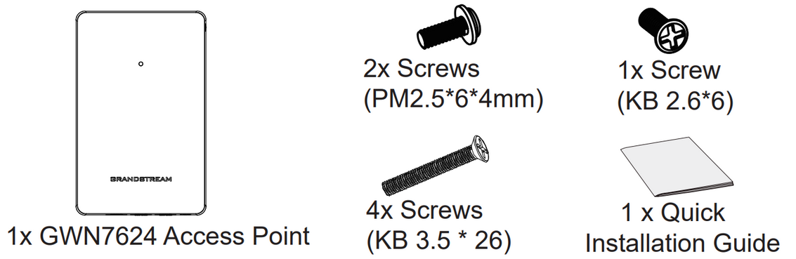
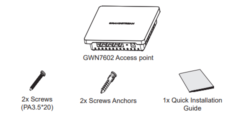


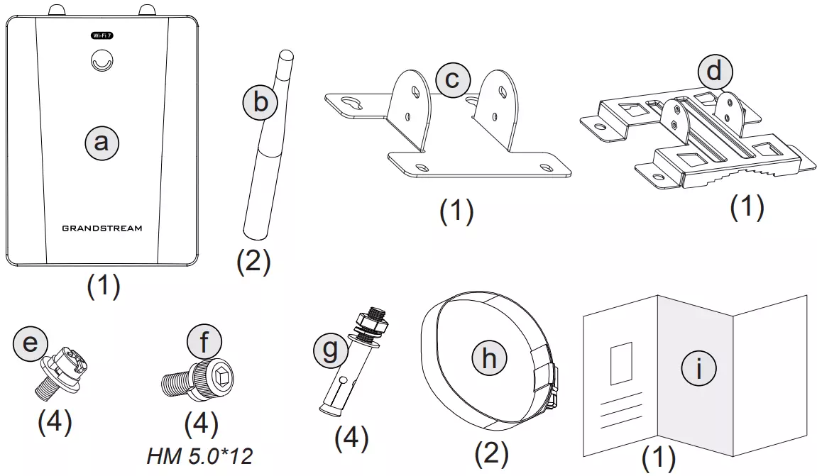
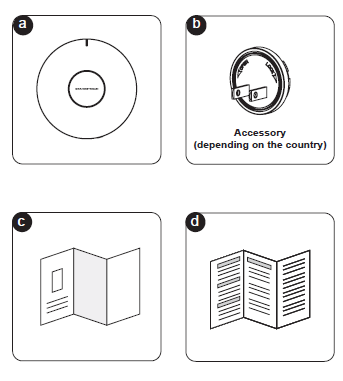
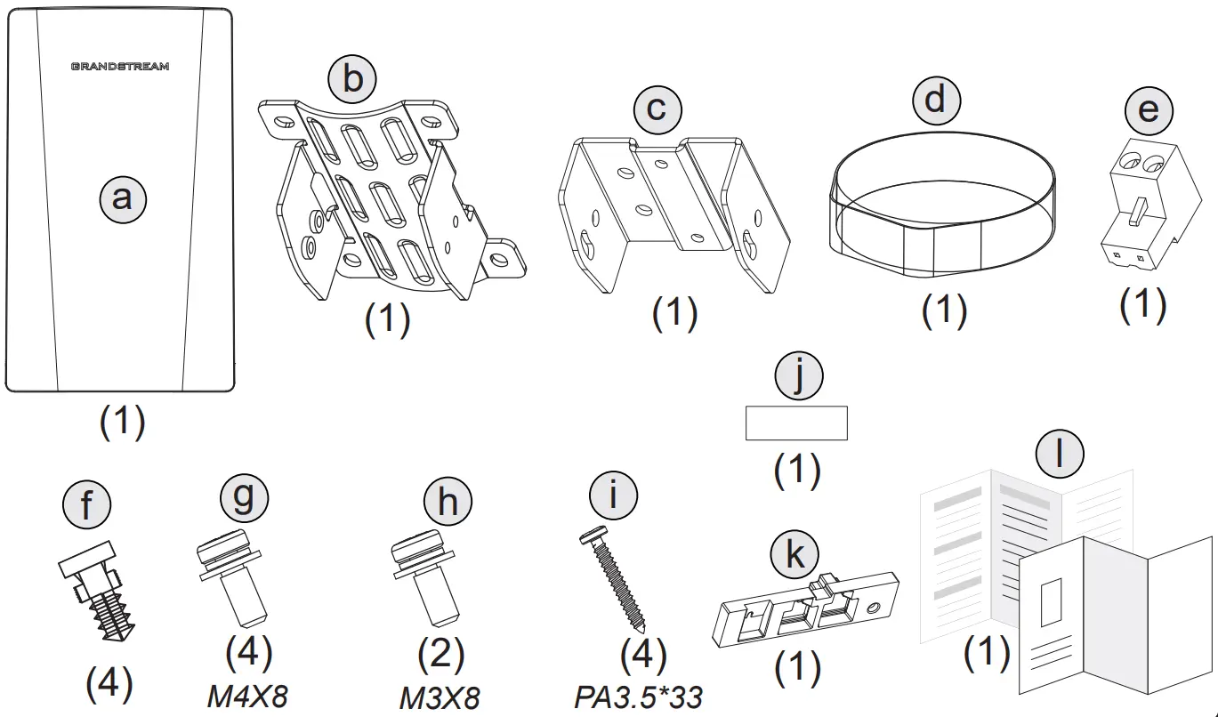

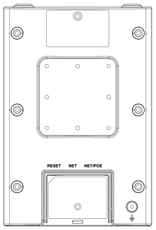
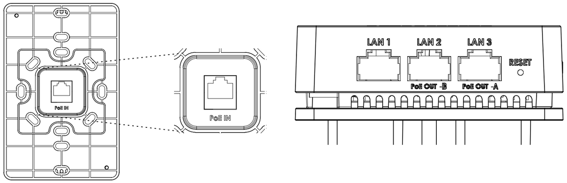
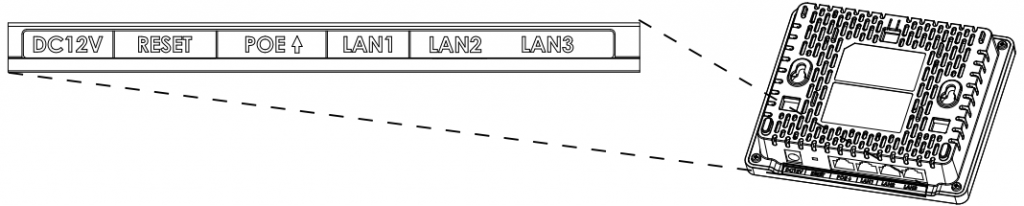
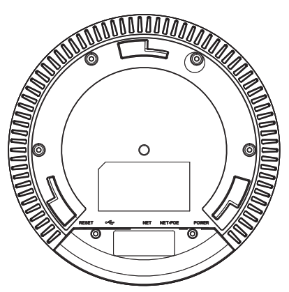


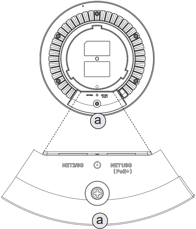
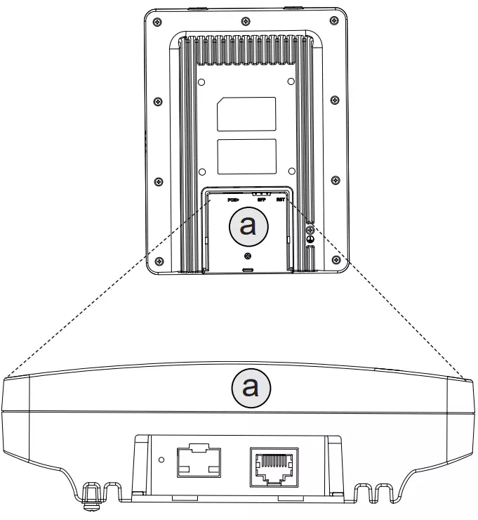


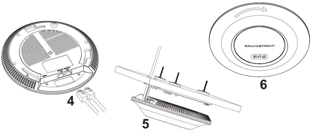
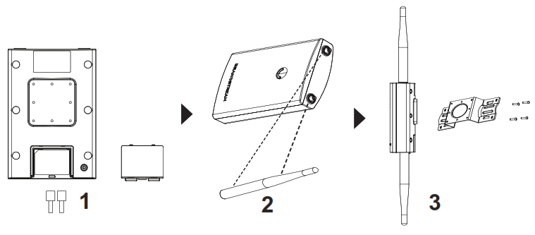
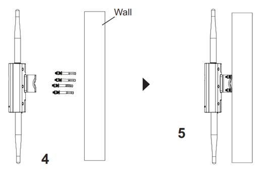
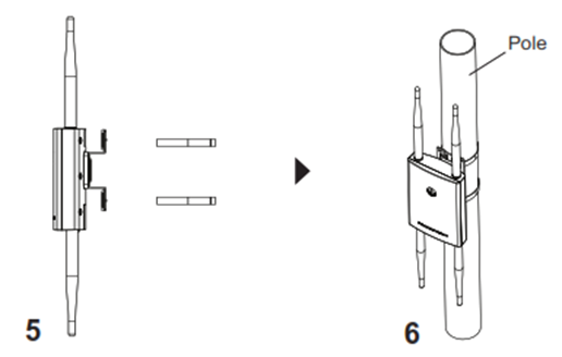
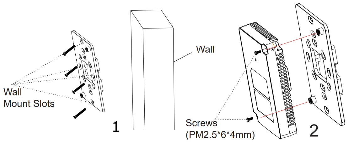
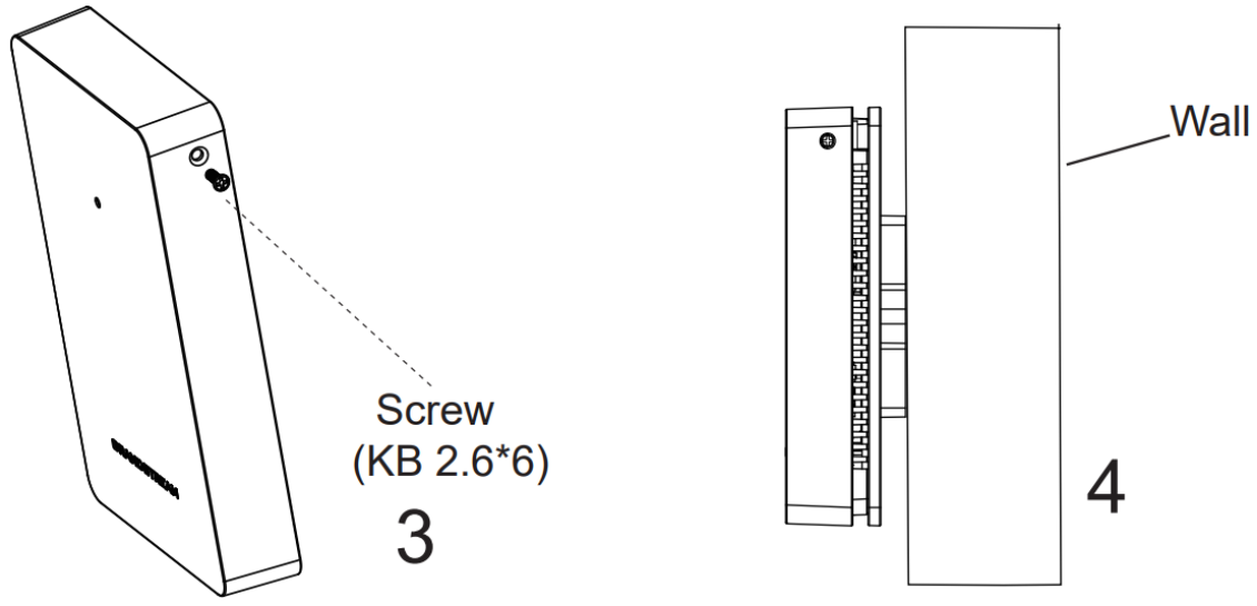
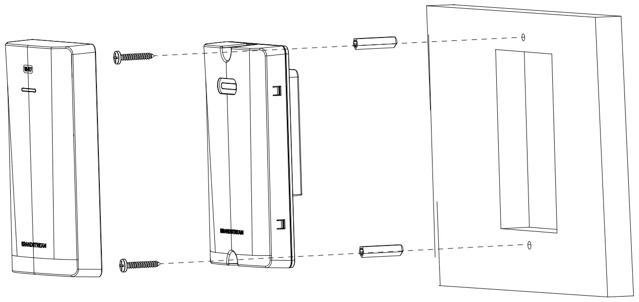
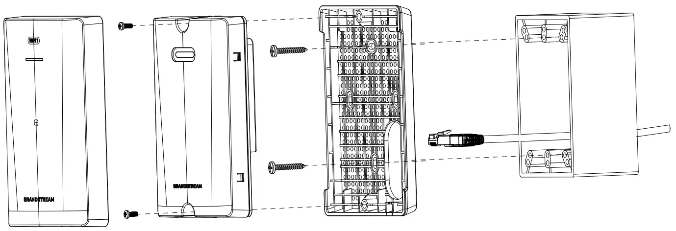
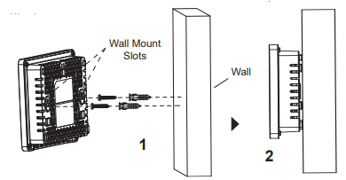


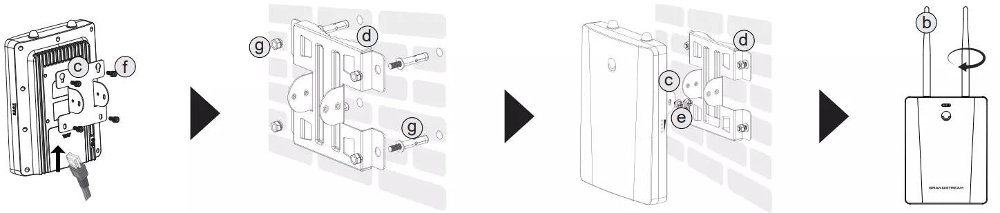
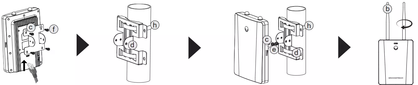

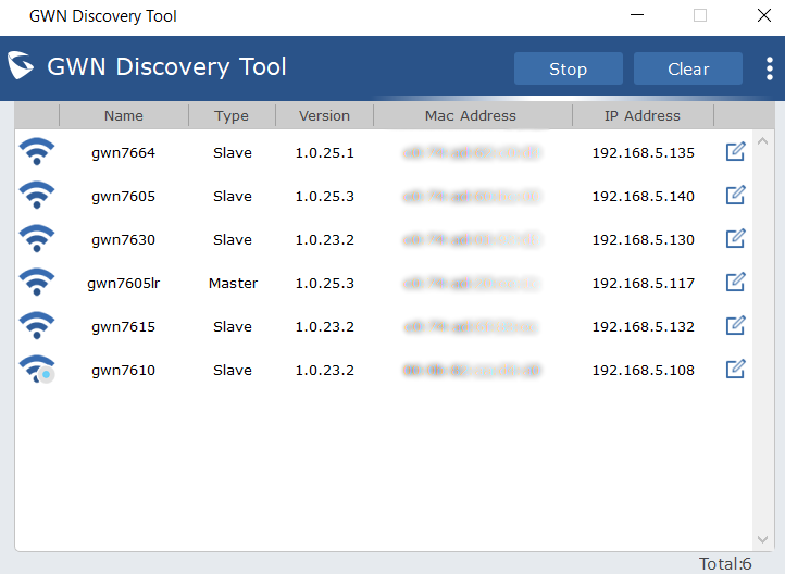
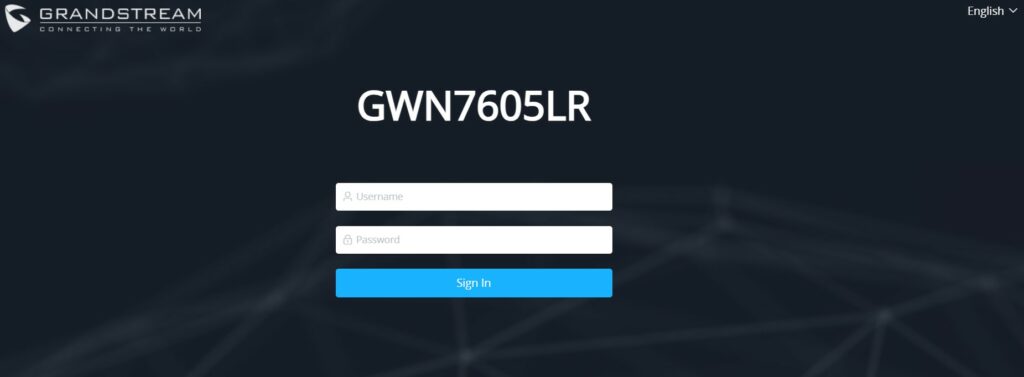
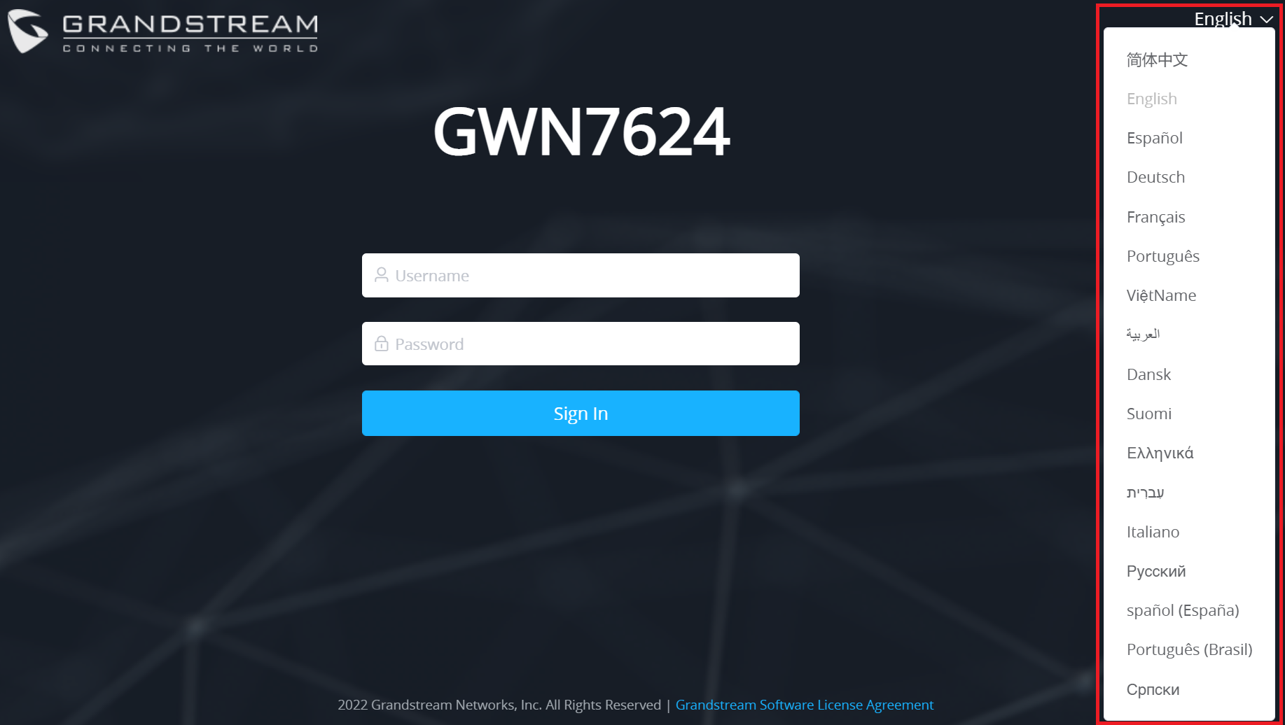
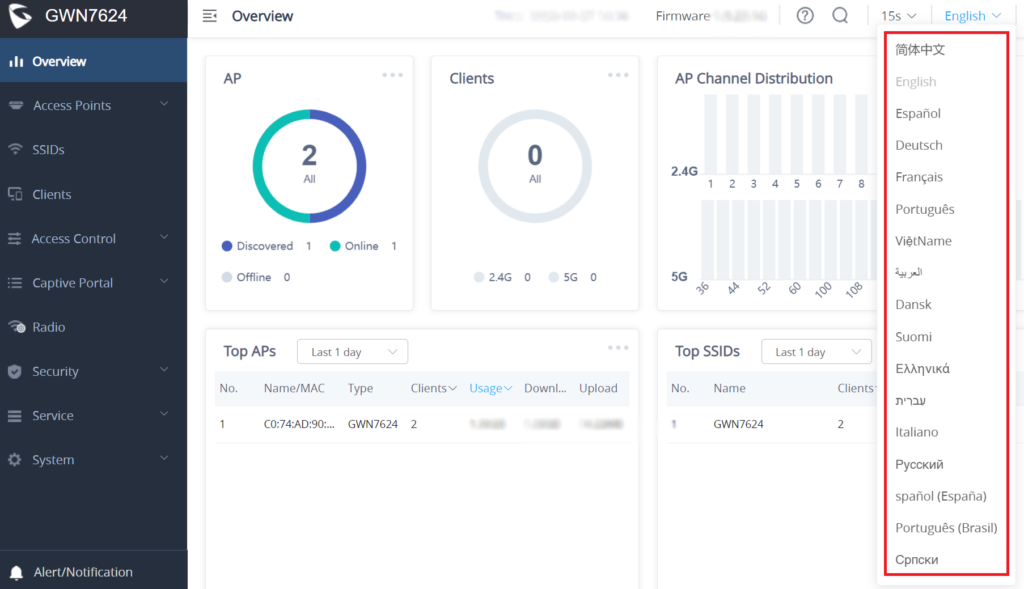
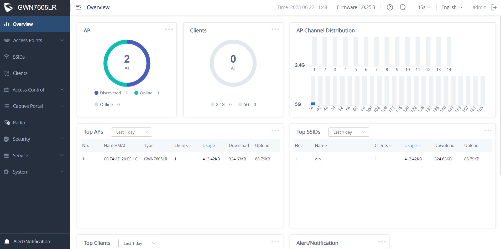
 to go to the Access Points page for basic and advanced configuration options for the APs.
 to go to the Clients page for more options.
 to go to the Access Points page for basic and advanced configuration options for the APs.
 to go to the SSID page for more options.
 to go to the Clients page for more options.
 to pop up the list of Alert and Notification.
 in the upper bar menu (Default is 15s).
  button to apply changes.
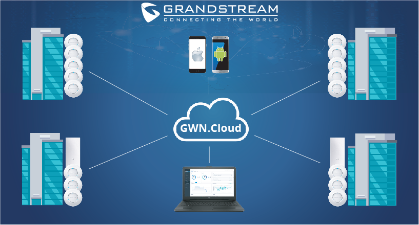
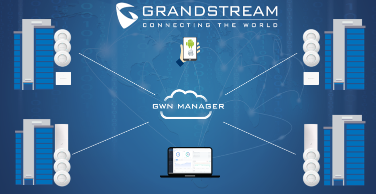
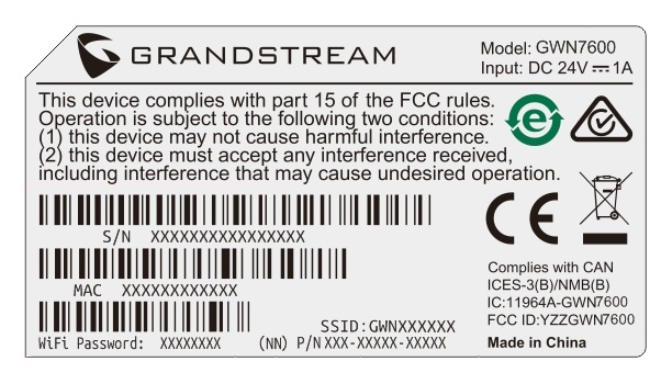
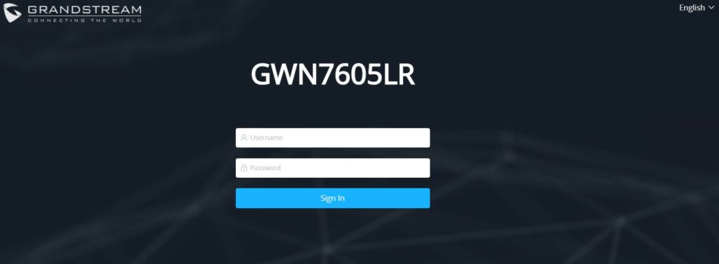
 while on the web interface.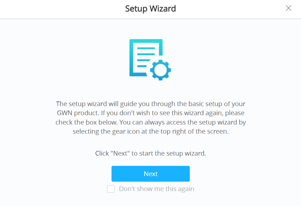
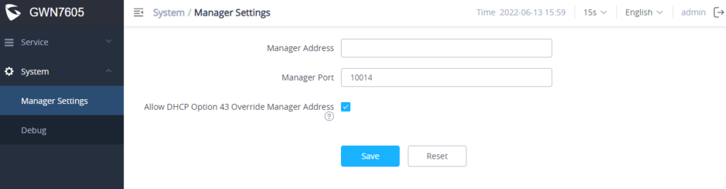
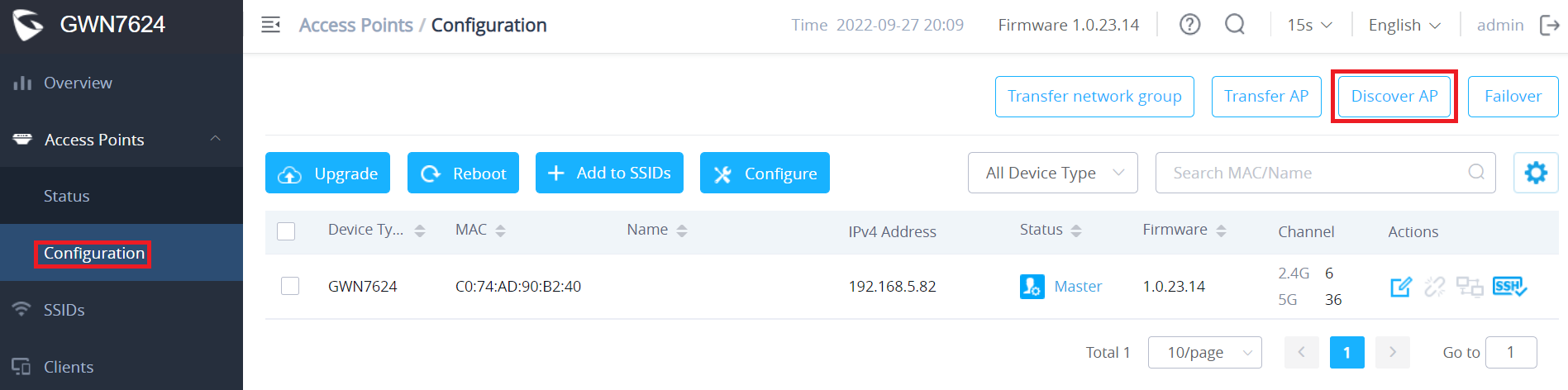
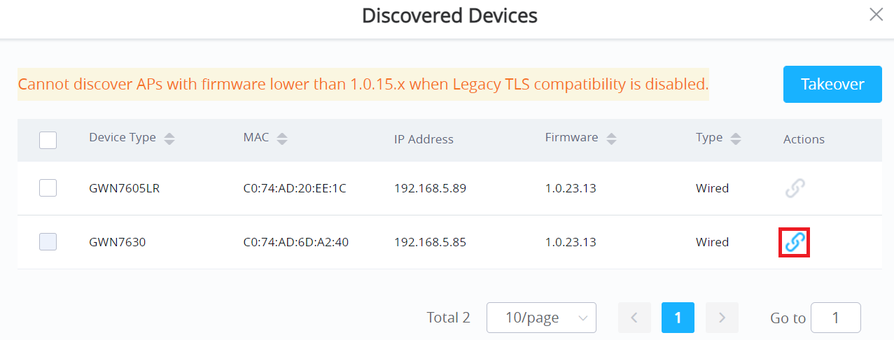
 to unpair it.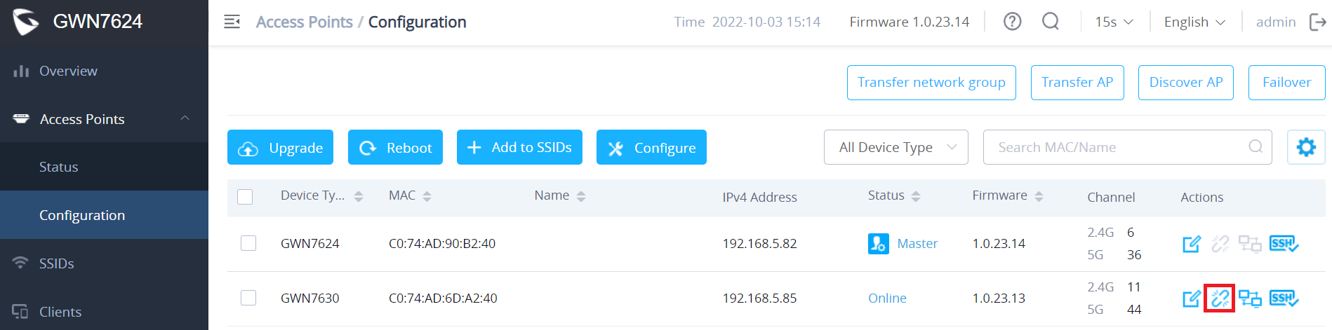
 near the desired AP, and its corresponding unit will start blinking the LEDs.
 When you already have Network/Wi-Fi configurations on your GWN account, using this feature will let you choose an existing Network/SSID to adopt your local AP.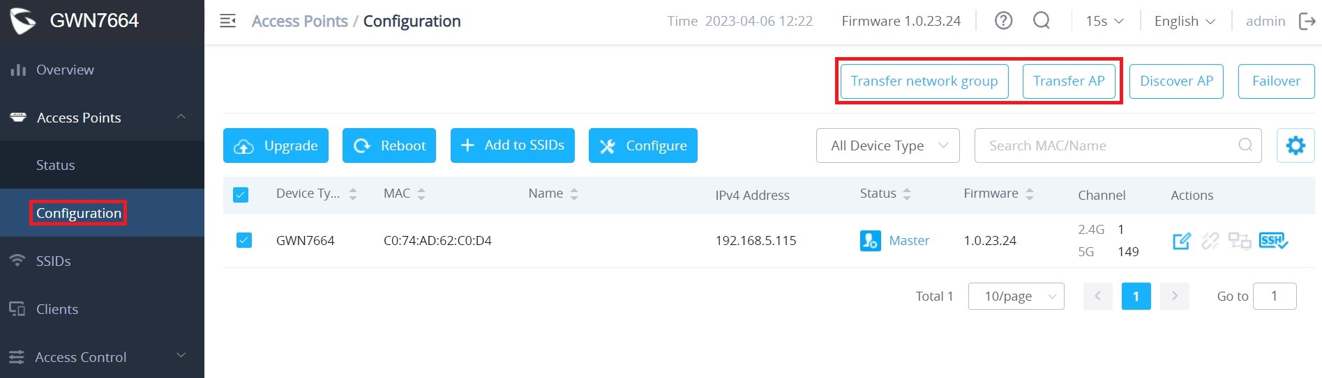
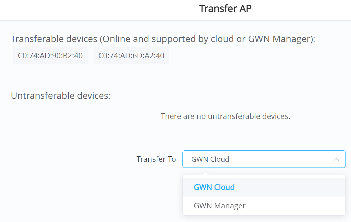
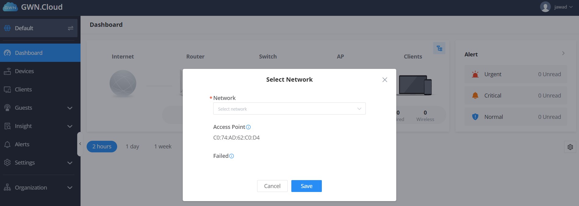
 will allow you to transfer your local configurations to your cloud account. For more details, please refer to the GDMS Networking – User Guide.
 and finally select the candidate access point from the drop-down list to be used as a Failover AP.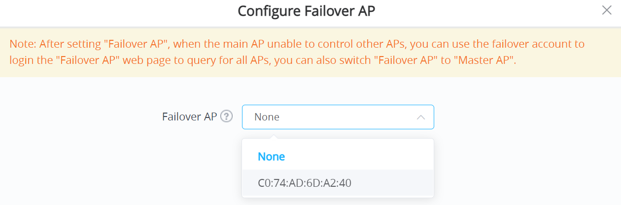
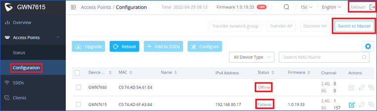
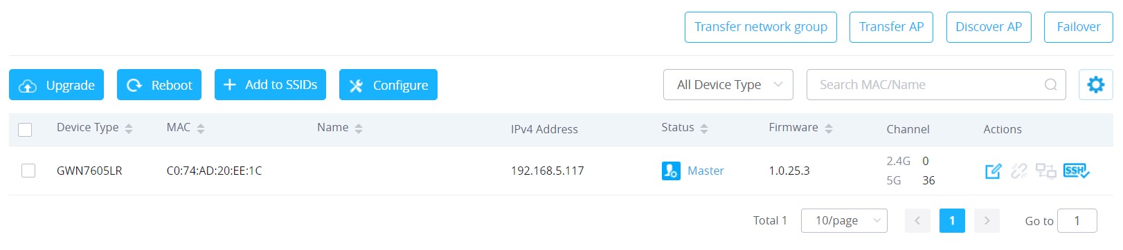
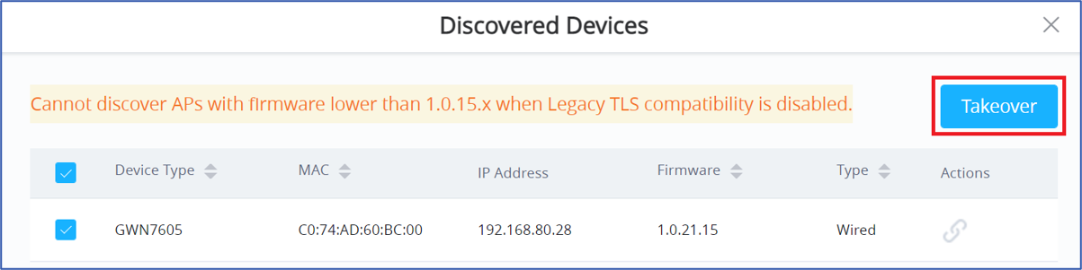
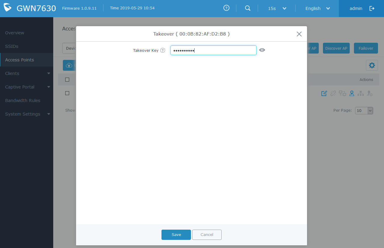

 button, the following warning message will prompt to confirm the procedure: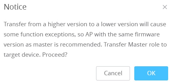

 Once an SSID has the Client Bridge Support enabled, the AP adopted in this SSID can be turned into Bridge Client mode by click the then the Bridge button
  .
.
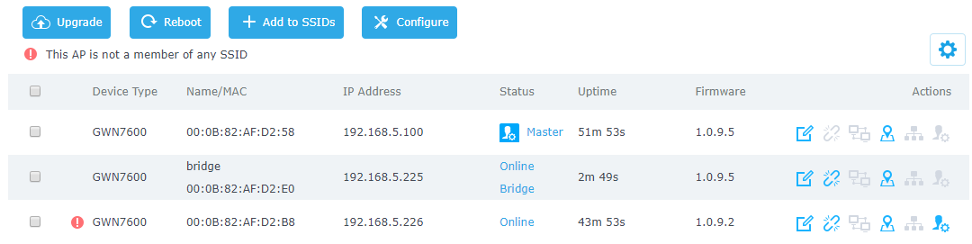
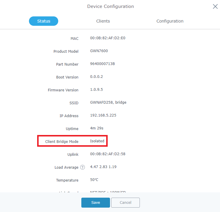
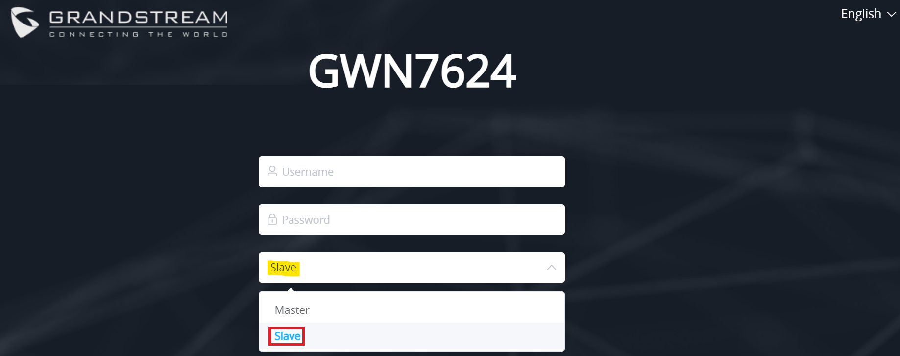
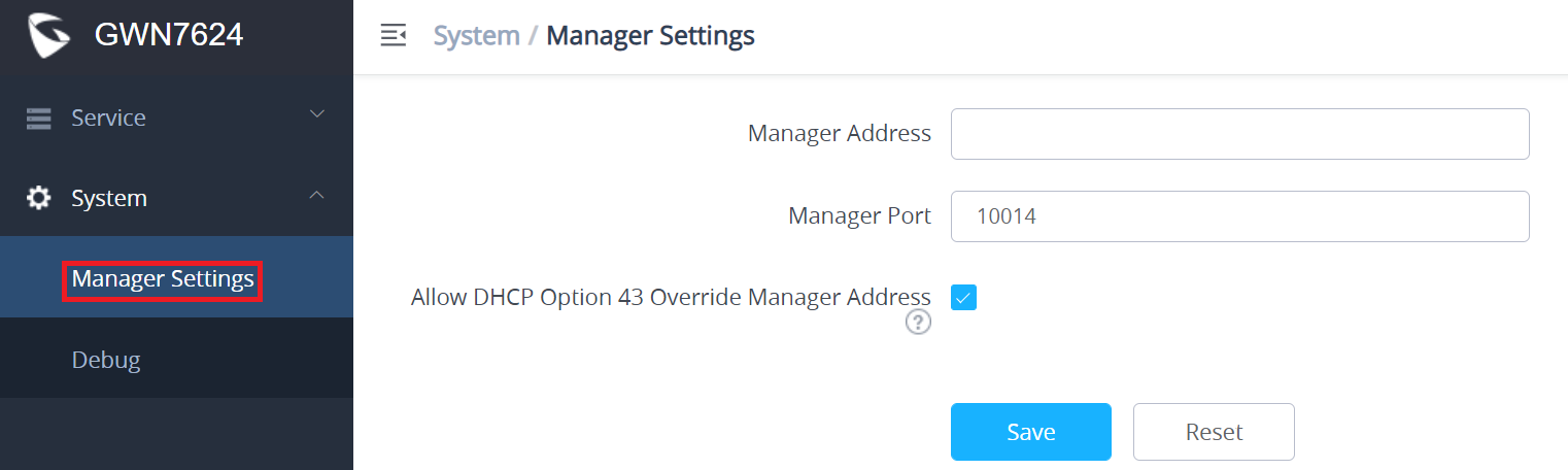
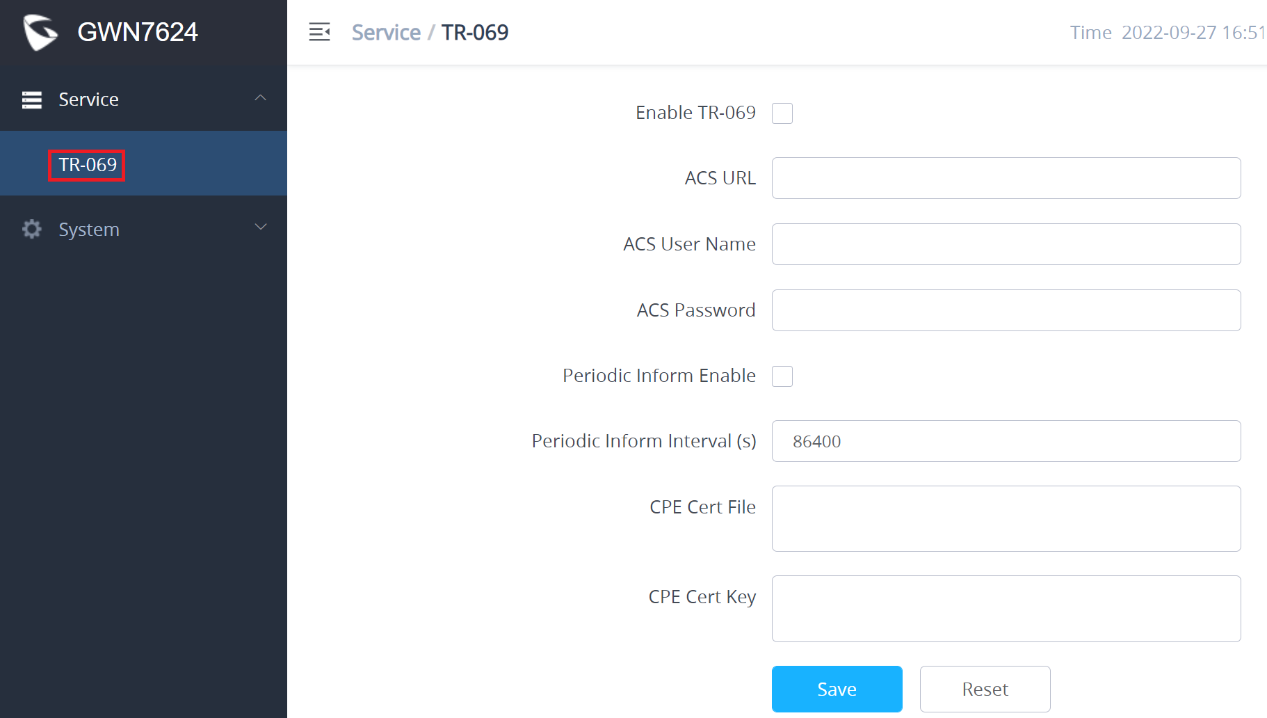



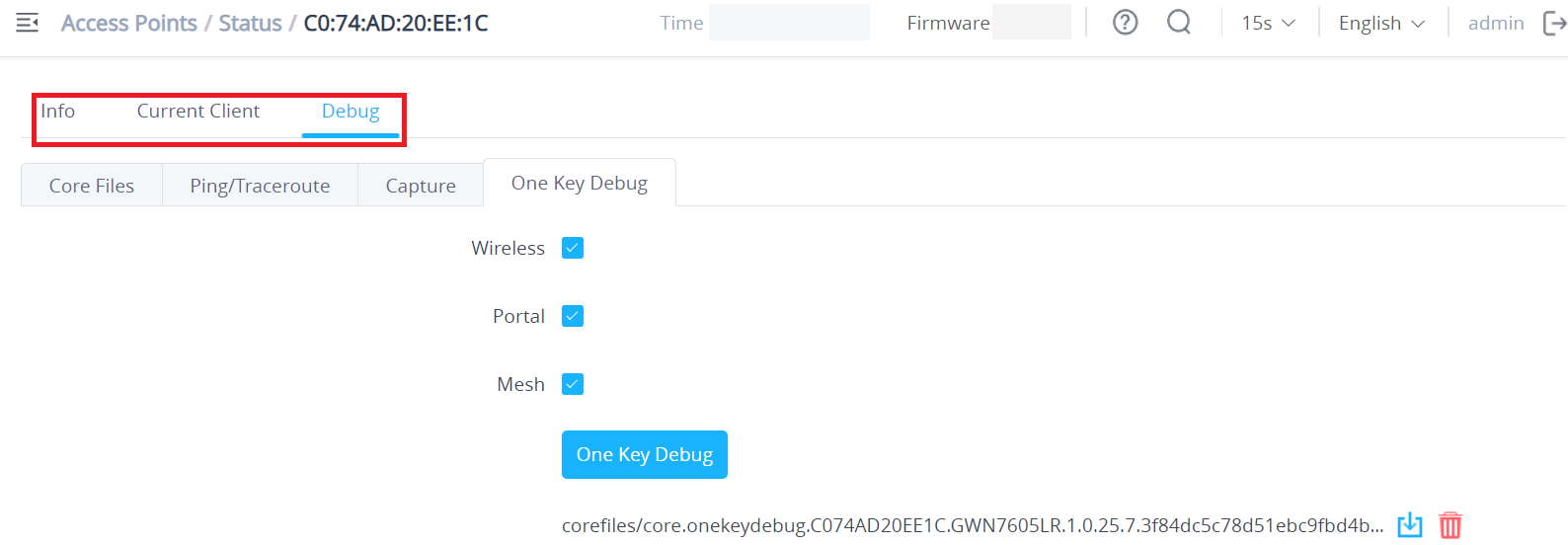
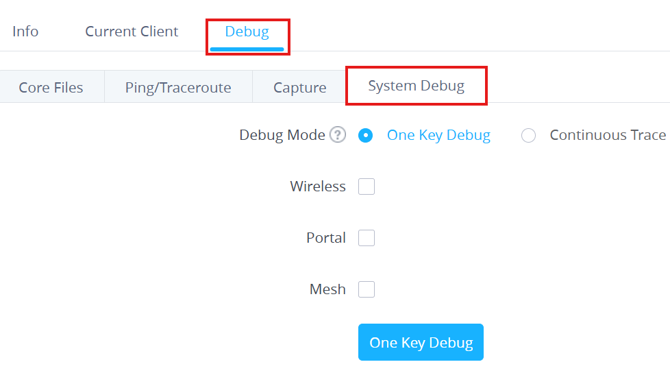
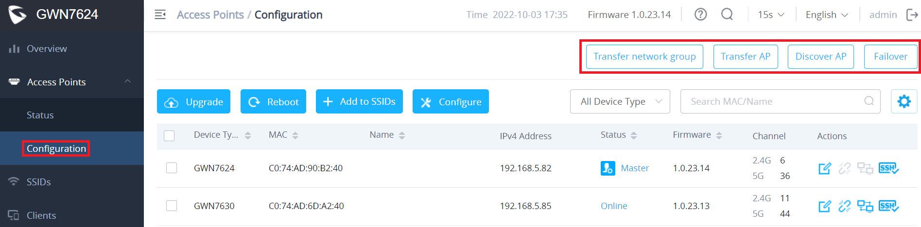
 button.
 button. the below confirmation message will be displayed: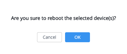
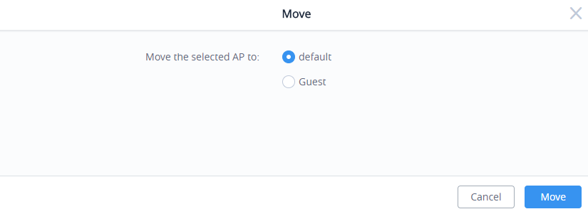
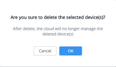
 button. A new config page will pop up: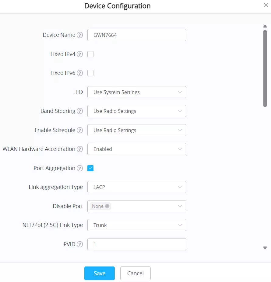

 button, a confirmation message will be displayed, click on
 to confirm the operation.
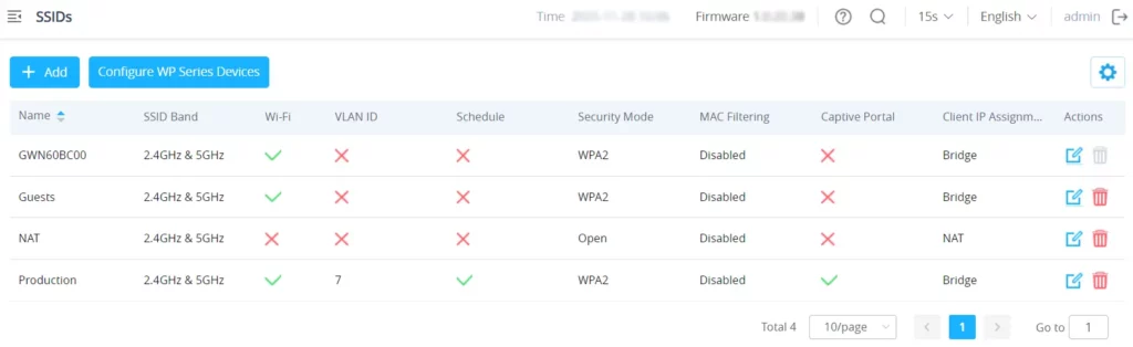

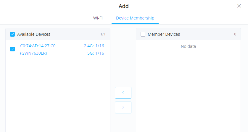
 to add the GWN76XX to the SSID or click on
 to remove it.


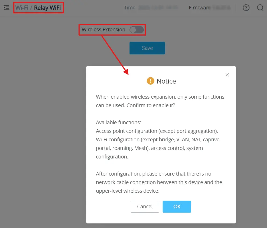
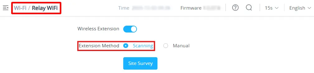
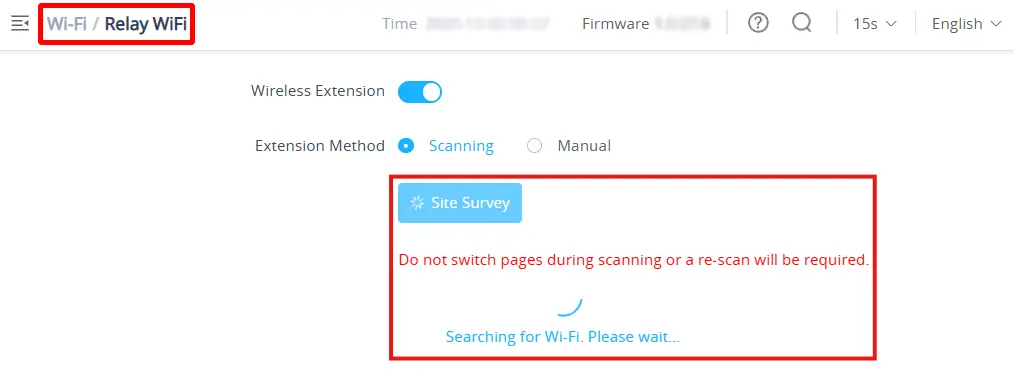
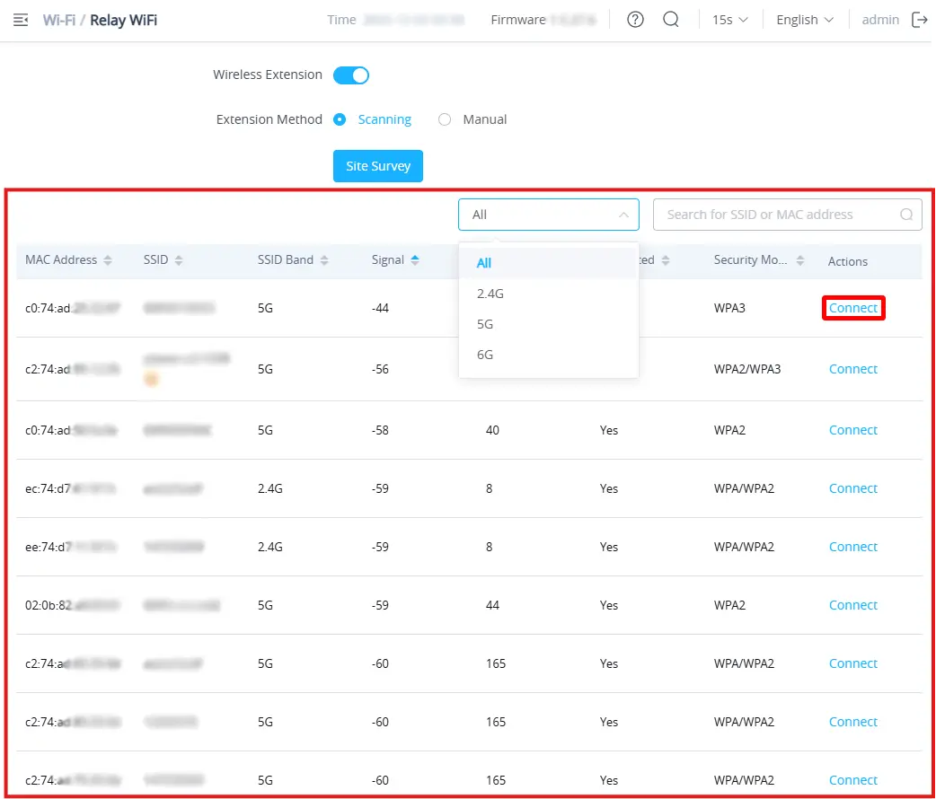
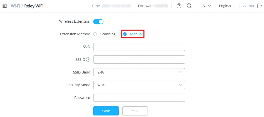
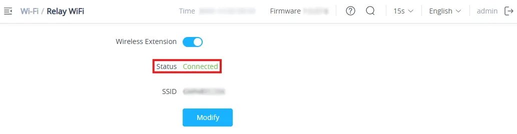
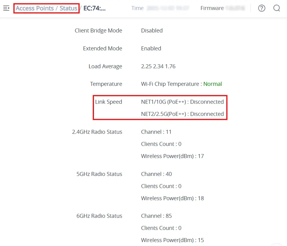



 button to customize items to display on the page. Following items are supported: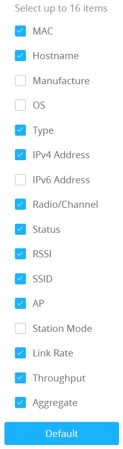

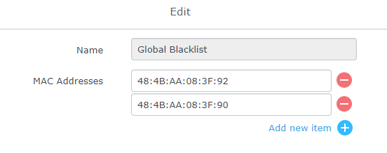
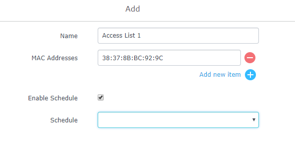
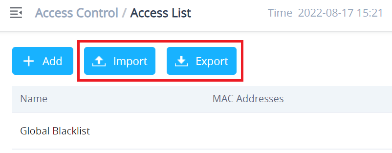

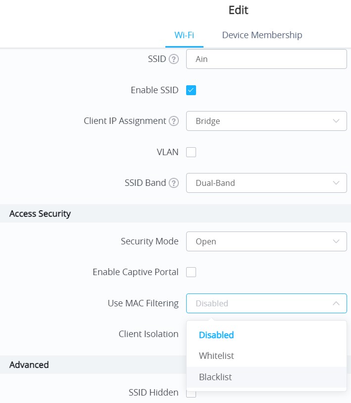
 .
.
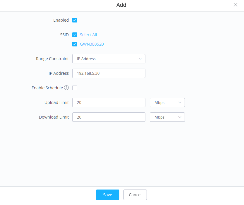
 to add a new rule. The following table explains the different options for bandwidth rules.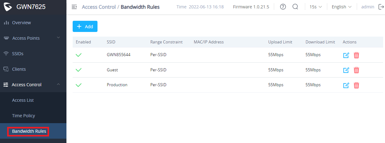
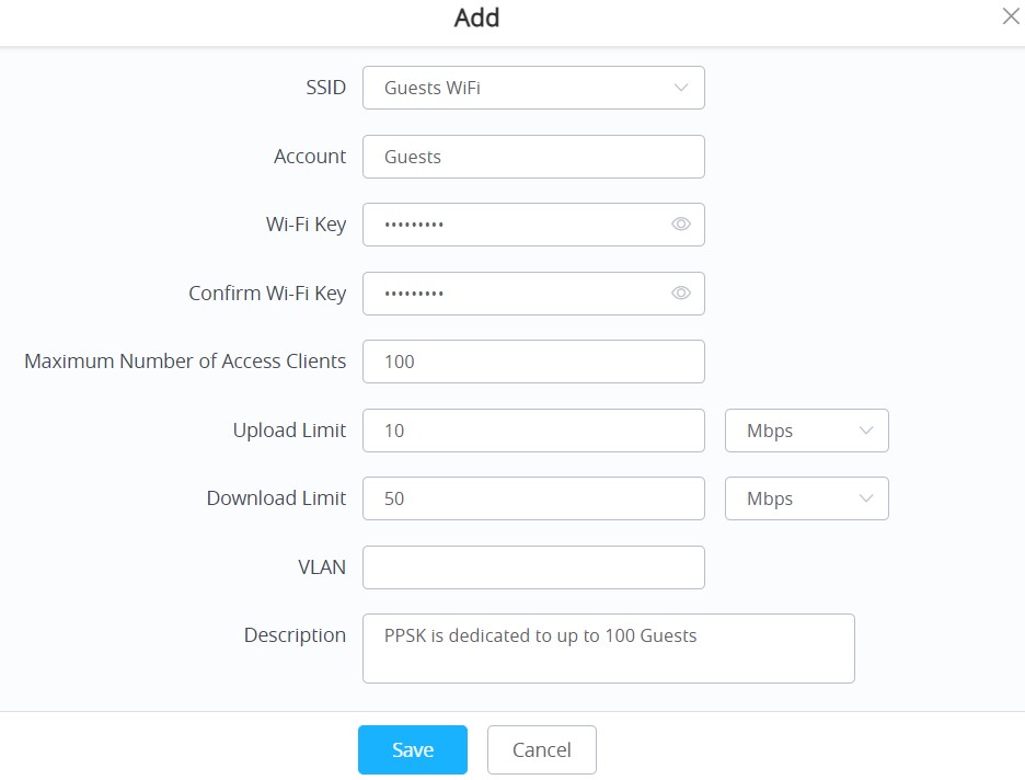
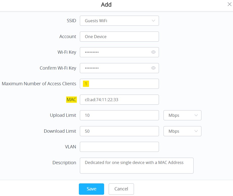
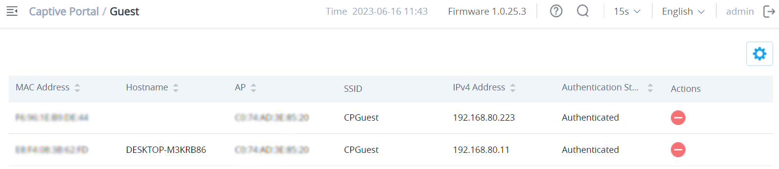
 to kick out connected clients.
 button to customize items to display on the page. Following items are supported: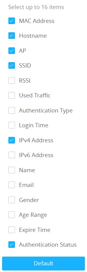
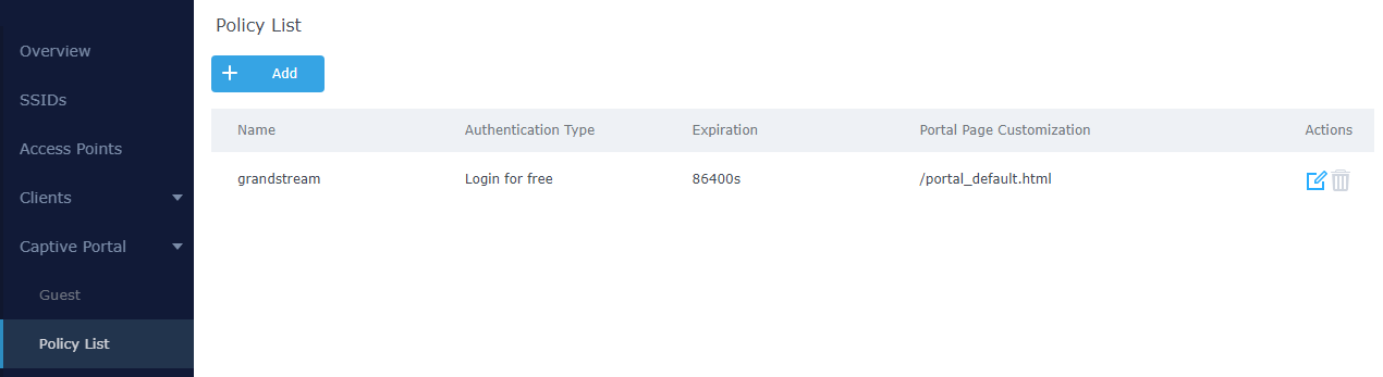



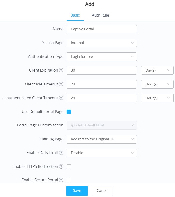


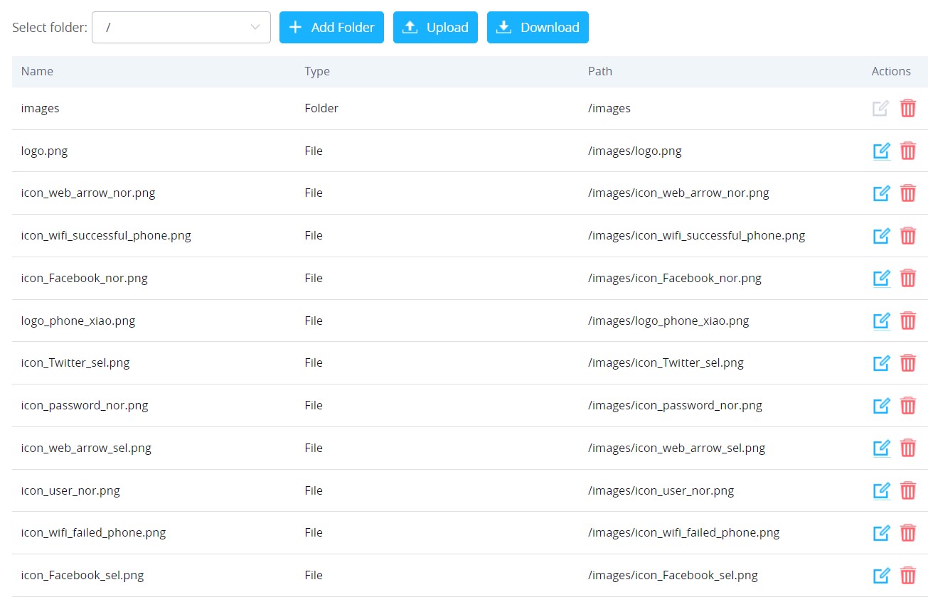
 .
.



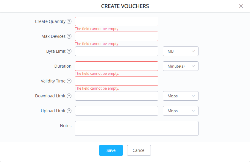

 and
and  to delete and print multiple vouchers or click
  button to print all vouchers at once.
 to filter the vouchers that were created at specific date-time.
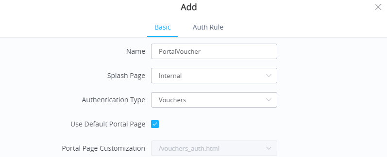
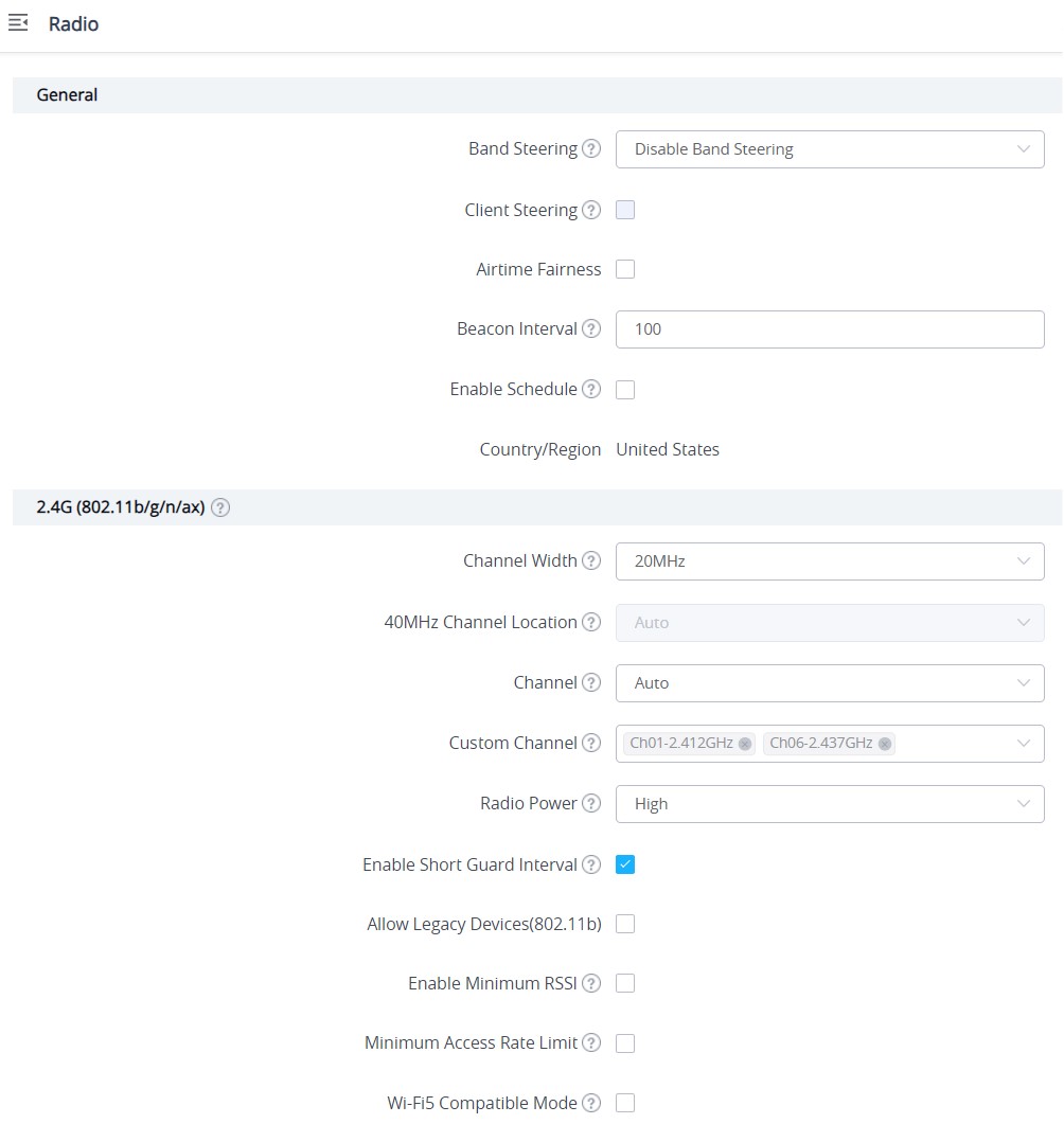
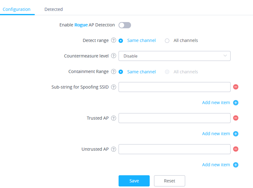



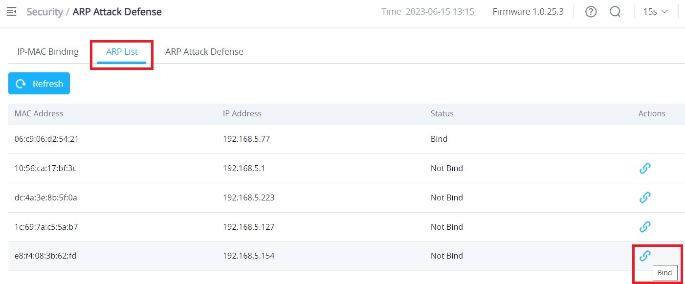
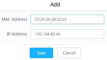
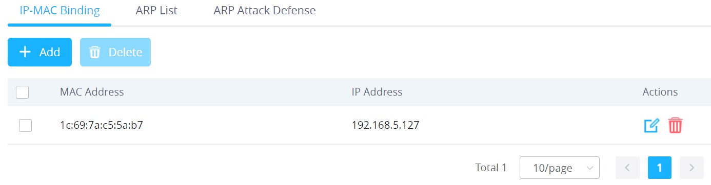
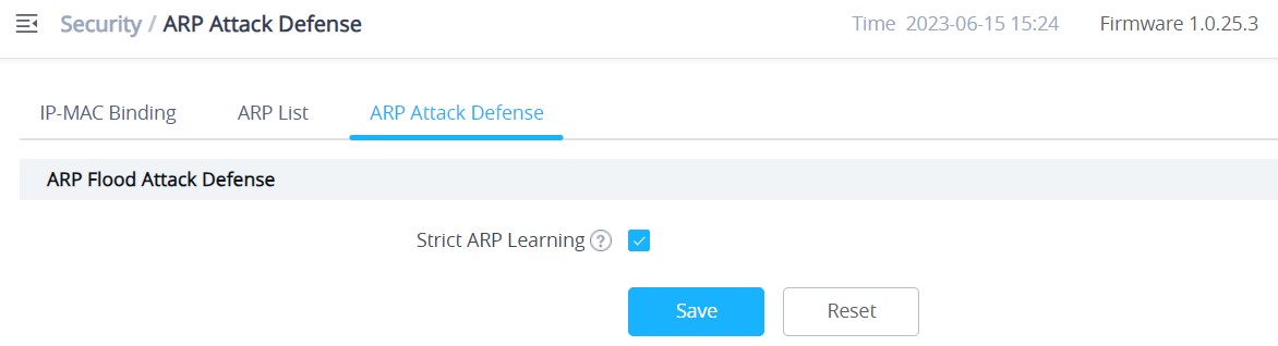
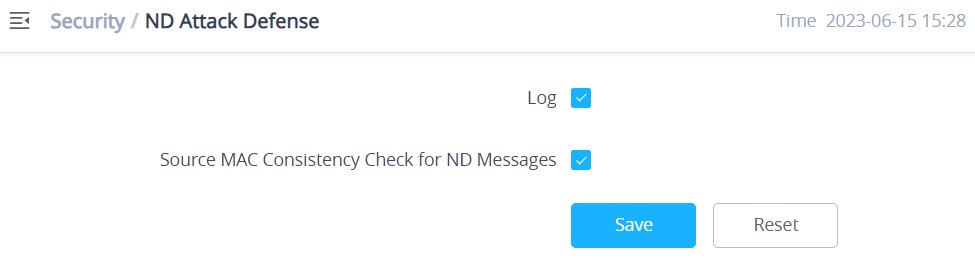
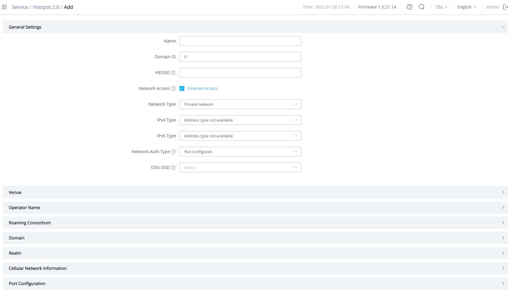
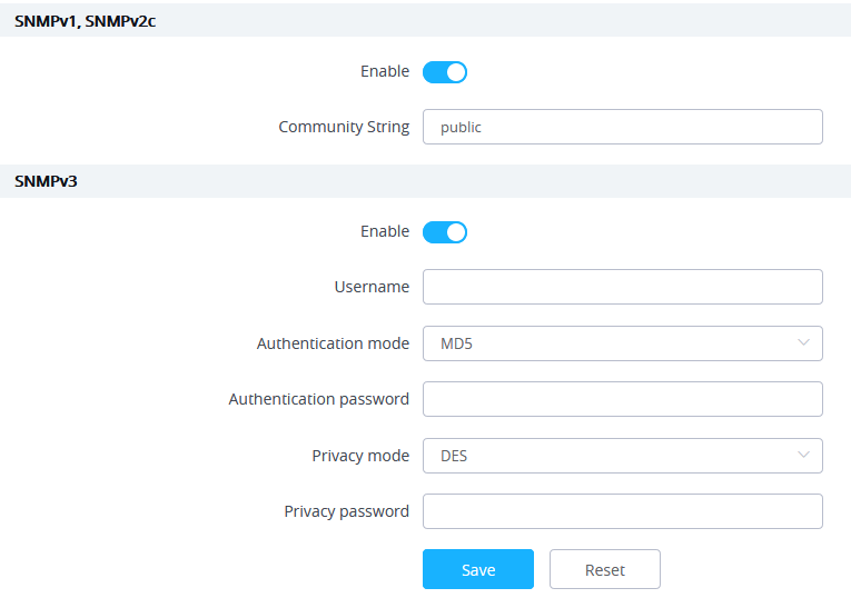

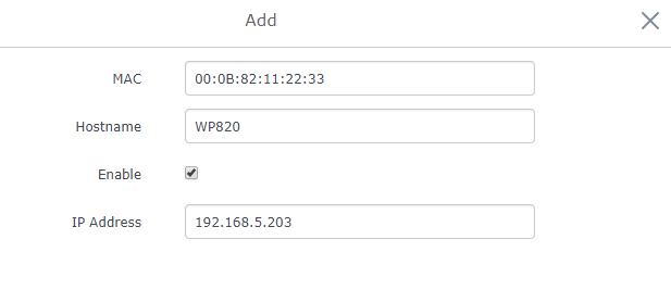
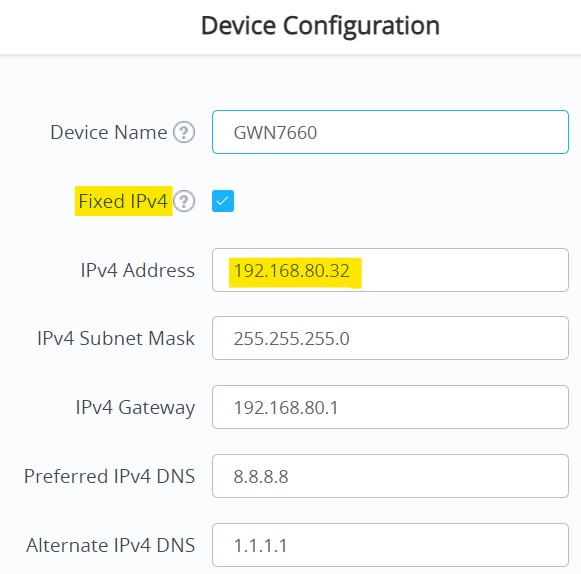
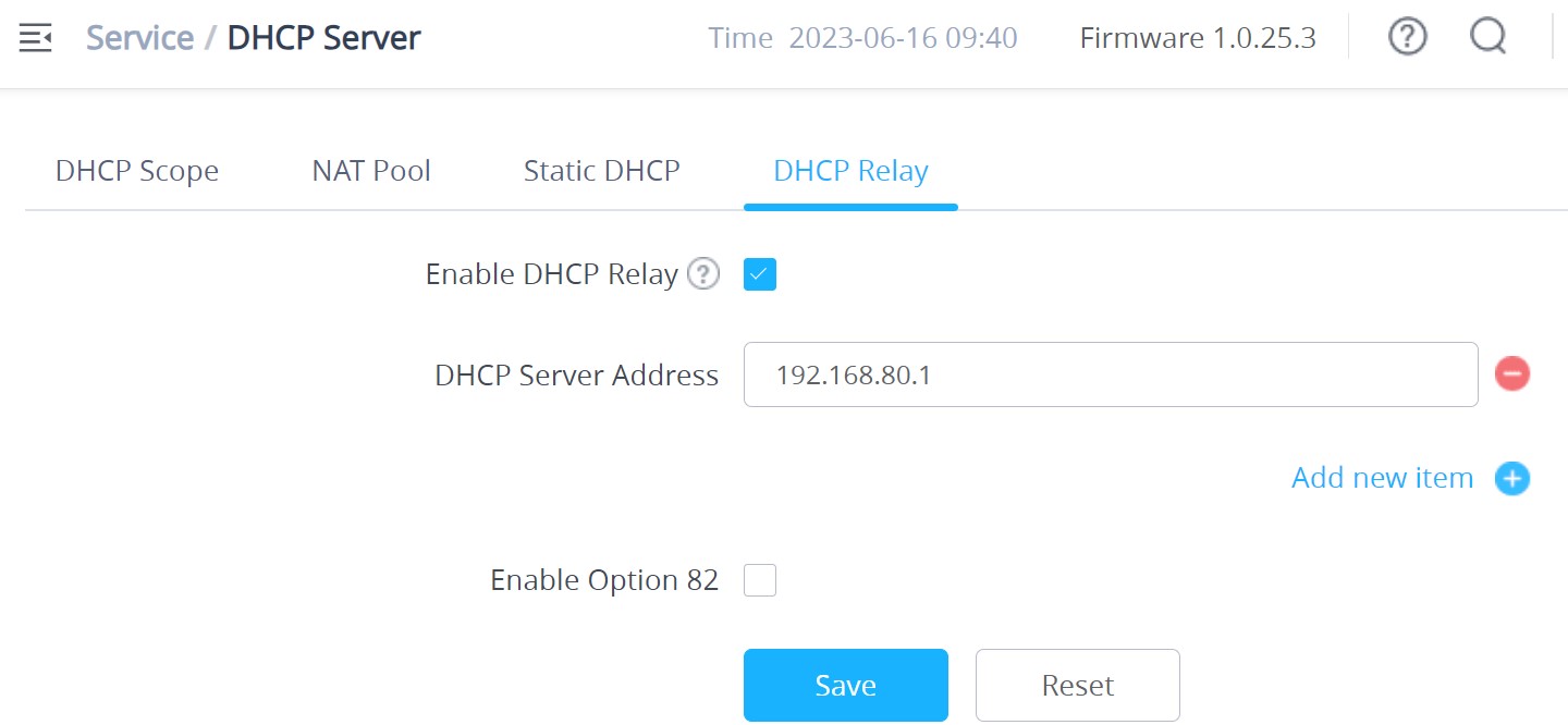
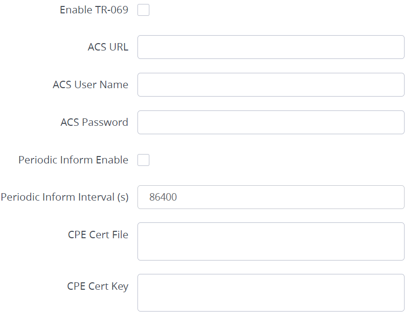

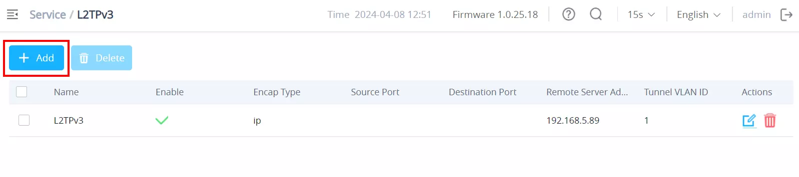
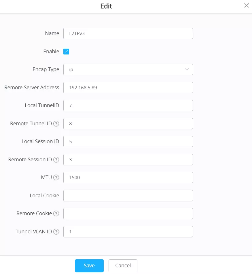


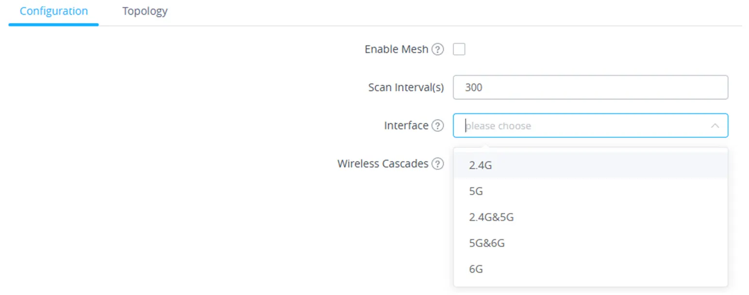

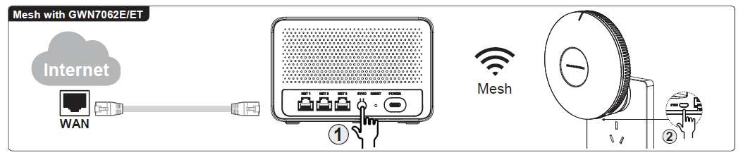
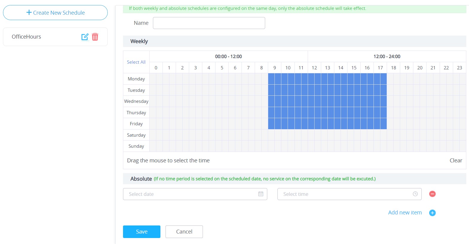
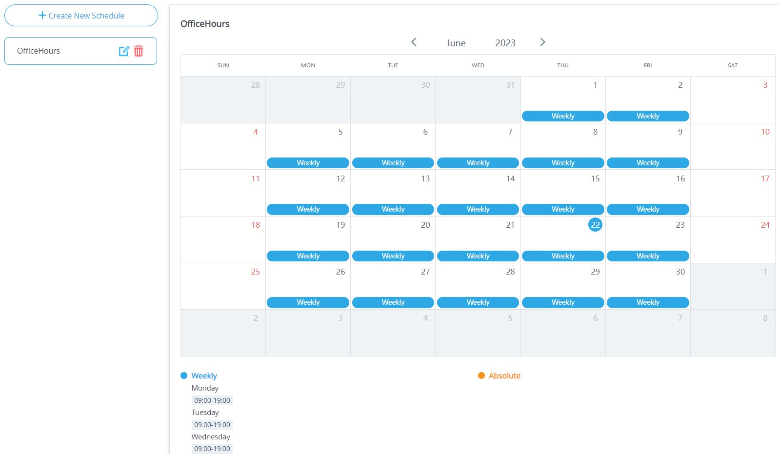
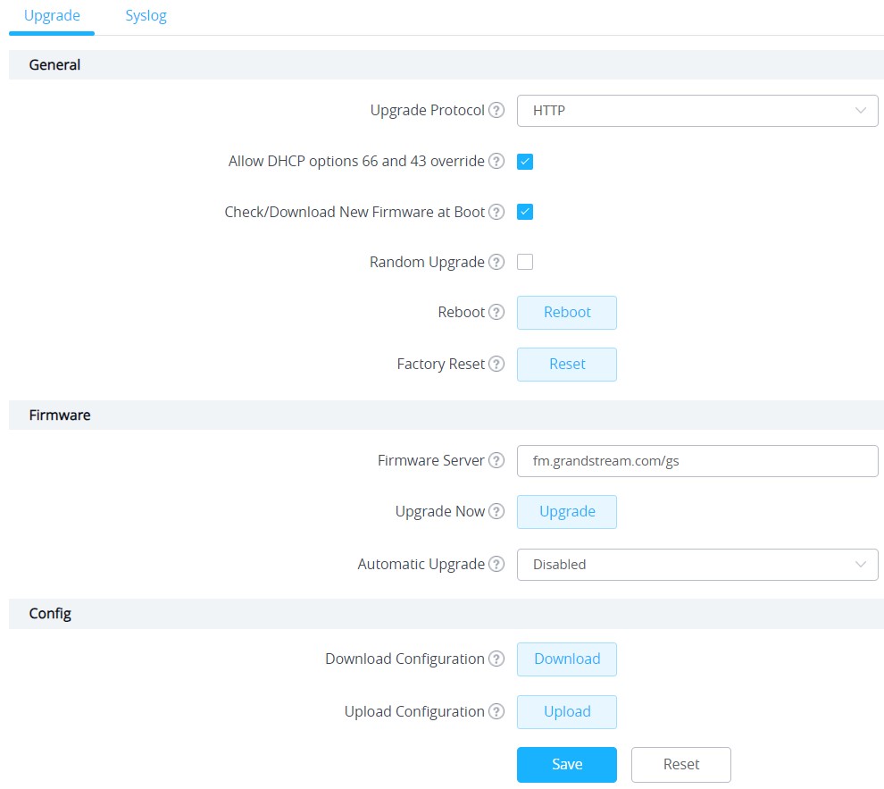
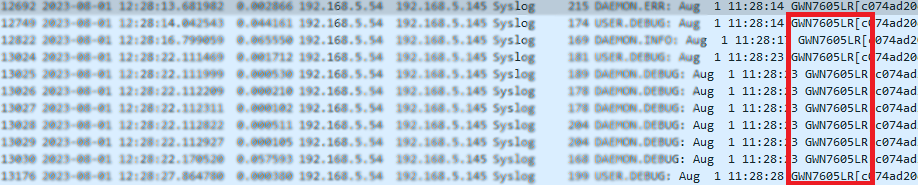
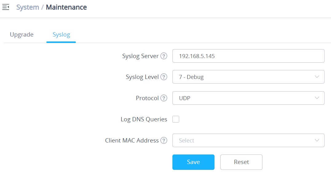
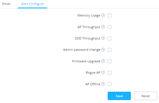
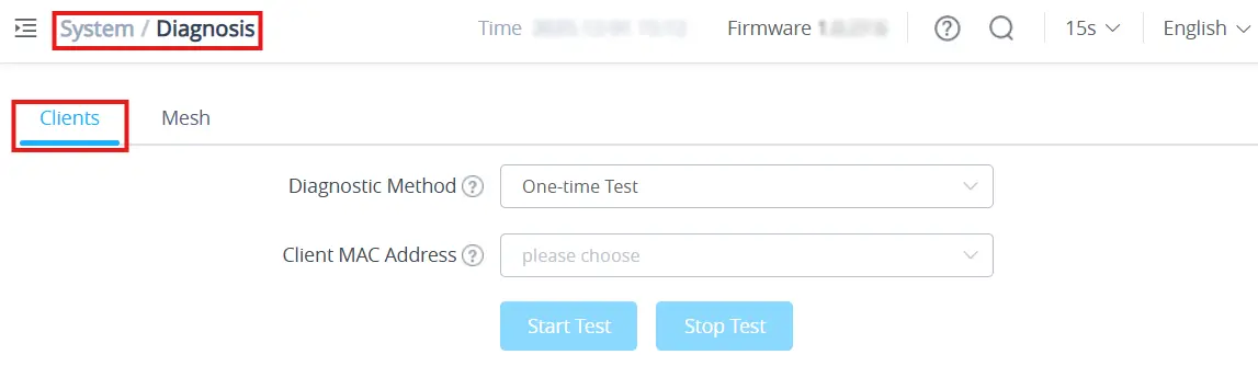
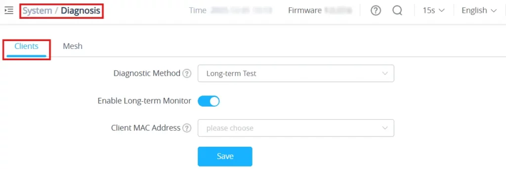
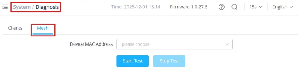


 to upgrade the selected paired access points.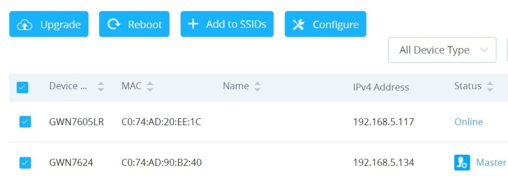
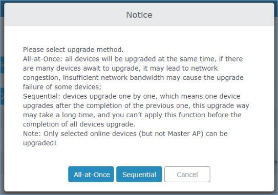
 will update you about the number of upgraded slaves out of the selected slaves.
 to download the configuration file locally.
 to browse for the configuration to upload.