Wireless Mesh Network is a wireless extension of the traditional wired network using multiple access points connected through wireless links to areas where wired access is not an option while also expanding the coverage of the WLAN network.
In the traditional WLAN network, the uplink of the AP is a wired network (usually an Ethernet Link):
- The advantages of a wired network are security, anti-interference, and stable bandwidth.
- The disadvantages are high construction cost, long period of planning and deployment, and difficulty of change in case a modification is needed.
However, these are precisely the advantages of wireless networks. As a result, Wireless Mesh Network is an effective complement to the wired network.
In addition, Mesh networking provides a mechanism for network redundancy. When an abnormality occurs in a wired network, an AP suffering the uplink failure can keep the data service continuity through its Mesh network.
The following list summarizes the advantages of using Mesh Wireless Network technology in conjunction with wired LANs:
- Rapid Deployment: Mesh network equipment is easy to set up and can be set up in a few hours, while the traditional wired + wireless network needs more time.
- Network Redundancy: Improve network reliability.
- Increasing network coverage dynamically: By continuously adding Mesh nodes, the coverage of Mesh networks can rapidly increase
- Flexible networking: APs can join or leave the network at any time as needed, which makes the network more flexible.
- More application scenarios: Mesh networks can be widely used in different scenarios such as warehouses, port terminals, and emergency communications, in addition to the common scenarios of traditional WLAN networks such as corporate networks and office networks.
- Cost-effective: In a Mesh network, only CAP nodes need access to a wired network, so that the dependence on the wired network can be reduced to the minimum, and this could save a lot of cost on purchasing wired devices and installing cables.
MESH NETWORK ARCHITECTURE
Terminology
A typical Mesh network architecture is as below:
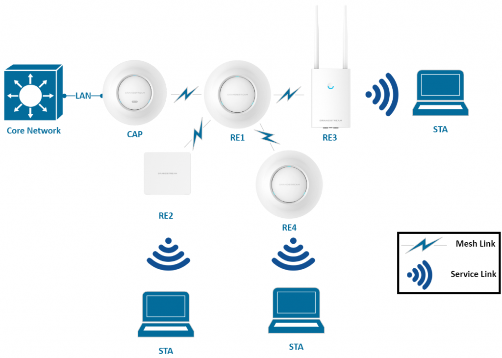
The following acronyms table explains the different components and words associated with this kind of architecture:
Acronym | Description |
AP | A generic wireless access point can be either a CAP or a RE. |
CAP | Central AP, an AP using a wired uplink. |
RE | Range Extender, an AP using a wireless uplink. |
STA | A regular wireless station/client (Smartphone, Tablet, Laptop…Etc). |
Mesh Link | A wireless uplink that is connecting two REs or one RE to a CAP. Note: Mesh supports only the 5GHz (due to the channel interference.) |
Service Link | A wireless link between an AP and an STA, is used for transferring actual user data. |
HT40, HT80 | These terms refer to High Throughput 40MHz or 80MHz, which is a technique used by 802.11n/ac devices to combine multiple 20MHz channels to have more data throughput. |
Mesh Network Architecture Models
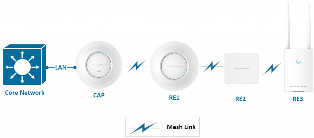
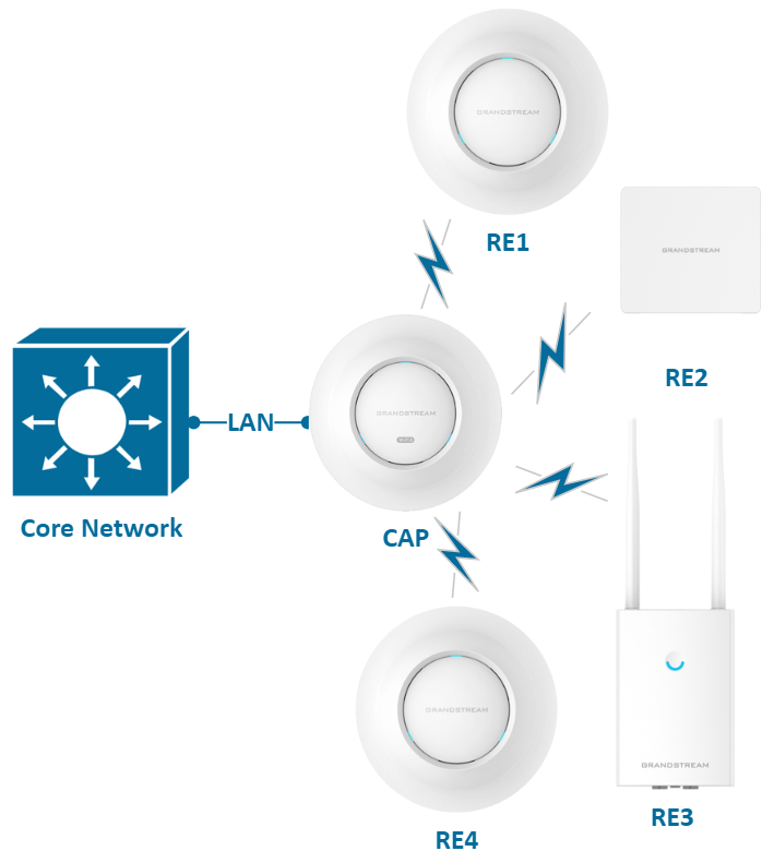
In actual networking, GWN Mesh networking mode can be abstracted into the following three modes: chain mode, star mode, and hierarchical star mode.
Each mode has its advantage and specifications about the environment where it is preferable to the other modes while taking into consideration more parameters such as radio conditions, capacity and bandwidth utilization…etc. These details will be discussed in the next chapters [CAP and RE Locating] [Topology Considerations] [Mesh Service Performance].
Chain Mode
In a chain networking environment, CAPs and REs are connected at a hierarchical level. This mode is applicable to networks requiring long transmission distances to cover more far ground where Ethernet wired connection is not available. Mesh links capacity should be taken into consideration in this mode, this will be discussed in more detail in the next chapters.
Star Mode
In a star networking environment, all REs are directly connected to the CAP for data forwarding. This mode is usually used for hotspot coverage in small squares. The remote REs directly connect to the root CAP through a wireless Mesh link to provide a wider range of wireless coverage services.
Hierarchical Star Mode
A hierarchical star network is also called a tree network. A hierarchical star network is composed of multiple levels of star structure connected vertically. In general, the closer a node is to the root of its tree, the better performance a node device can have. Compared to a star network, a Hierarchical star network has larger coverage and the benefit of easy expansion.
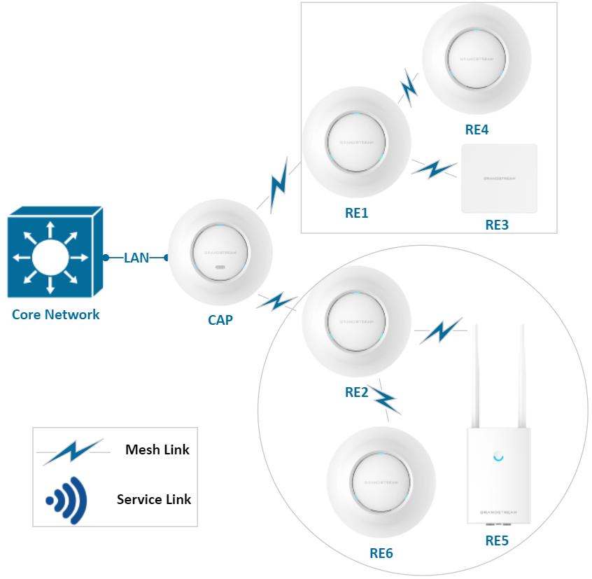
Each mode has its advantage and specifications about the environment where it is preferable to the other modes while taking into consideration more parameters such as radio conditions, capacity and bandwidth utilization…etc. These details will be discussed in the next chapters.
MESH NETWORK PLANNING
CAP and RE Locating
When installing GWN access points in an environment while taking advantage of the mesh network capability introduced, installers should take the following points into consideration:
- The air radio link between adjacent APs’ antennas must be completely visible and no major obstruction in between.
- The relative height of the AP installation is recommended not to exceed 4 meters to prevent interaction with other peripheral APs.
- The location of CAP requires a reachable wired network, so cabling and mounting need to be considered, CAP is better to be deployed in a relatively open and unobstructed location to facilitate reliable communication with multiple RE devices in the vicinity.
- Due to the instability of the wireless link and its sensitivity to interference, a Wireless Mesh Network is perfect for the deployment in which wired network deployment is inconvenient but air interference is relatively little.
- Each access point should be within the range of the uplink RE or CAP access point to ensure the establishment of the mesh link, below table gives 3 examples of GWN76XX Max coverage range:
AP Model | GWN7605 | GWN7664 | GWN7660LR |
Max. Coverage range | 165 m | 175 m | 250 m |
Topology Considerations
Typical networking topologies are covered in [Mesh Network Architecture Models] above. These topologies can be used as basic models for building Mesh Networks in various scenarios.
Mesh network technology focuses more on ensuring large coverage rather than capacity. Therefore, it is not suitable as a basic solution for multi-user high-capacity and concurrency scenarios. In such cases, it is recommended to combine a mesh network with an increase of wired CAPs for multi-user high-capacity areas.
The following are some factors needed to be considered while planning.
Maximum Hops
Adjacent cascade APs signals are in the same channel, which results in a great decrease of data throughput. The more hops are constructed, the lower the data throughput will be.
The typical performance calculation formula is 1 / N (1 / N of CAP air interface bandwidth), where N is the number of hops. It can be considered that the performance decreases inversely with the number of hops. Since STAs also use the same wireless channel, which causes extra usage within this channel, the recommended max number of hops is 3.
Maximum number of directly connected REs for each CAP
The number of REs attached to a CAP (Central Access Point) affects the throughput of users. When more than the suggested number of REs are linked to a CAP and the wireless clients accessing the network for high data usages such as video streaming or large file download, then the CAP can easily become the bottleneck of the whole Mesh network. Especially while knowing that each AP can allow a large number of client associations as shown in the table below:
AP model | GWN7615 | GWN7660LR | GWN7664 |
Number of clients supported | 200 | 256 | 512 |
Therefore, you need to control the number of REs and the number of users that are attached to each CAP, increase the number of CAPs, and increase the bandwidth reserved for data service. We recommend the setups for each topology model:
- Chain network mode: recommended maximum hop of RE is 3, that is, the number of RE does not exceed three.
- Star networking mode: recommended max number of REs directly connected to CAP is 4.
- Hierarchical star mode: no more than 2 RE branches are recommended under the CAP and
no more than 2 second-level REs are connected to each first-level RE.
Mesh Service Performance
Mesh channel: Available options are: 5GHz, 5GHz & 2.4GHz, and 5GHz & 6GHz. The supported bands depend on the model’s capabilities.
The choice of channel width: it is recommended to use HT40 mode or HT80 with 5GHz channel to provide a higher rate.
Mesh Service Degradation
For the scenario in the figure below, we can assume the following:
- Mesh links use the same 5G channel.
- The 1st hop air interface bandwidth is C (Mbps) and the hop count is N.
- RE1 and RE2 respectively generate a fixed flow.
- Mesh links use the HT40 mode, and CAP provides 180Mbps bandwidth for 1×1 terminals.
In this model, traffic from RE1 to CAP occupies the 5G channel once, while traffic from RE2 to CAP occupies the 5G channel twice.
We can come up with this formula: The peak throughput of each node in this system is C / N, and the average throughput of each RE is 2C / (N * (N + 1)) (where N is the total number of hops).
Example of bandwidth estimation: The traffic on RE1 is sent to the CAP using the 5G channel once, so the peak bandwidth is 180/1 = 180Mbps; The traffic on RE2 is sent to the CAP using the 5G channel twice, so the peak bandwidth is 180/2 = 90 Mbps; The average bandwidth of RE1 and RE2 is (2 * 180) / (2 * (2 + 1)) = 60 Mbps.
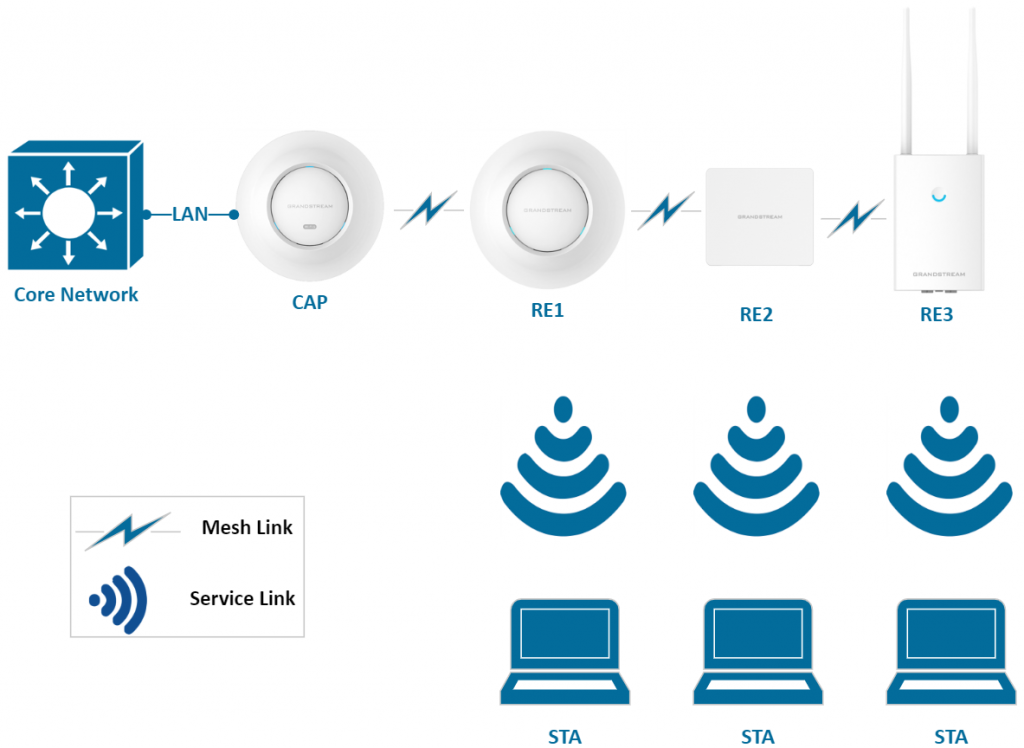
Our calculation only considers the attenuation ratio. Data is only for reference. We put C = 98 in to the table below:
AP | Hops | Channel | Terminal Type | Packet Type | Channel Width | Channel | Downward Throughput in Mbps | C/N | Attenuation Ratio |
CAP | 0 | 5G | 1×1 | TCP | HT40 | 161 | 98 | ||
RE1 | 1 | 5G | 1×1 | TCP | HT40 | 161 | 43 | 98 | -56.1% |
RE2 | 2 | 5G | 1×1 | TCP | HT40 | 161 | 29 | 49 | -32.6% |
RE3 | 3 | 5G | 1×1 | TCP | HT40 | 161 | 19 | 33 | -34.5% |
It can be concluded that the more hops are in the system, the more degradation the performance has. So, it is suggested that use as less hops as possible in your deployment.
MESH DEPLOYMENT AND HANDLING PRECAUTIONS
The following is a list of recommendations that should be taken into consideration when deploying a mesh network solution:
- Mesh feature is mutually exclusive with client bridge feature. That is, if the client bridge function is configured, you cannot configure Mesh.
- In Mesh networking, if a RE is connected with a wired network, the Mesh link will be disconnected and this RE will be selected as CAP. If a CAP’s wired network is disconnected, it will turn itself into a RE.
- Mesh links and service links of each CAP use the same channel. Mesh link and service link cannot be divided into different channels, so it is suggested that the channel should be uniformly planned in the early stage of network deployment.
- Disable Automatic Uplink Failover is not recommended, and the default is unchecked.
- To ensure service bandwidth, it is recommended that users control the scale of the network.
- Some operations may cause the RE to be disconnected. You must reconnect the RE with an Ethernet cable to recover it. For example, disable the Mesh function after the Mesh link is established, or Disable the Automatic Uplink Failover function. Please be aware of such changes.
- Unconfigured REs can only be found by CAP in the same LAN and cannot be found simultaneously on multi-LAN CAPs.
MESH NETWORK SAMPLE CASE
Overview and Network Architecture
In order to meet the Wi-Fi coverage requirement of a certain office and reduce the cost of wiring construction. A company uses Mesh technology to deploy a network as shown on the diagram below:
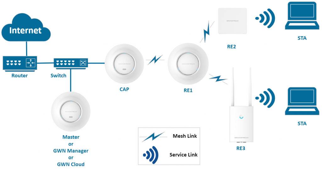
- The router is a GWN7000 acting as the default gateway for the network.
- The switch takes the role of DHCP server to assign the IP addresses to APs and stations.
- GWN7600LR is acting as the Master, to manage all APs on the network.
- Slave CAP is connected to the switch using an Ethernet cable.
- RE1, RE2, and RE3 access the wireless network by using Mesh technology (RE1 is the first hop connected directly to the CAP node).
Mesh Configuration Steps
- Prepare the CAP Access Point:
- Ensure the CAP access point are deployed and operational. The CAP can also act as the master controller of the network.
- Pair RE Access Points with the CAP:
- Connect all REs to the same wired LAN (same VLAN) as the master.
- Perform the discovery and pairing process through the CAP’s interface.
- After pairing, deploy the REs in their respective locations to complete the setup.
- Configure Global Mesh Settings:
- On GWN76XX, navigate to System → Settings → Mesh and configure the following parameters:

Field | Description |
Enable Mesh | Activates the Mesh feature. Default is disabled. |
Scan Interval | Interval in minutes to scan for available Mesh neighbors. Must be an integer between 1 and 5. |
Interface | Configures the wireless band used for Mesh backhaul connections between access points. Depending on the device model and its hardware capabilities, one or more of the following options may be available:
Notes:
|
Wireless Cascades | Defines the number of APs that can be cascaded wirelessly. Must be an integer between 1 and 3. |
Mesh configuration on GWN76XX
- Manage the Mesh Network:
Once deployed and paired, manage all slave access points (REs) through the master (CAP).
Access the “Access Points” page on the CAPs’s interface:
- APs in the “Online Wireless” state are REs with a wireless uplink to a CAP.
- APs in the “Online” state are connected via a wired link.

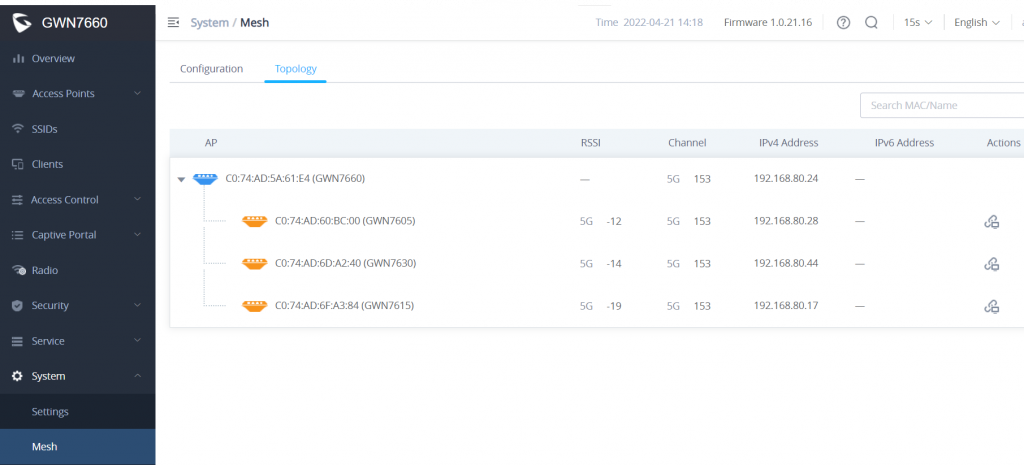
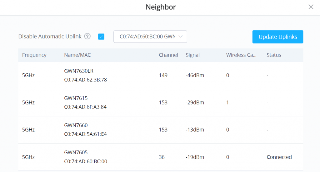
Once you click on an AP Action icon, the feature Automatic Uplink Failover is enabled By default, and we do not recommend disabling it, Since, without automatic uplink failover, RE will not be able to come back online once the wireless uplink is down.