


This guide provides step-by-step instructions for deploying Grandstream’s latest GWN series of Wi-Fi access points (APs). For instance, imagine a high-density office space struggling with network slowdowns due to overlapping signals and outdated infrastructure. This guide addresses such challenges by providing solutions for managing high-density environments, minimizing interference, and ensuring robust security. Designed for enterprise network integrators and IT administrators, the guide emphasizes strategies to maximize network performance using the latest wireless technologies and standards.
WLAN Technical Features
The latest Grandstream GWN access points (APs) come equipped with state-of-the-art WLAN technologies, delivering optimal performance, scalability, and security. Key technical features include:
Advanced Wi-Fi Technologies
- Orthogonal Frequency-Division Multiple Access (OFDMA): Introduced with Wi-Fi 6 and continued in Wi-Fi 6E and Wi-Fi 7, this technology allows simultaneous communication with multiple devices, reducing latency and improving efficiency, particularly in high-density environments.
- Multi-User MIMO (MU-MIMO): Introduced with Wi-Fi 5 and enhanced in Wi-Fi 6 and beyond, MU-MIMO serves multiple devices concurrently, boosting throughput. Wi-Fi 6 expands its capability to support more simultaneous streams, ideal for dense deployments.
- Target Wake Time (TWT): A feature introduced with Wi-Fi 6, TWT extends battery life for IoT and mobile devices by scheduling communication times.
- Enhanced Spectrum Use:
- Wi-Fi 6E: Utilizes the 6 GHz band for reduced interference and higher bandwidth.
- Wi-Fi 7: Introduces Multi-Link Operation (MLO) and 320 MHz channels for unparalleled reliability and speed, perfect for AR/VR applications.
Improved Coverage and Performance
- Beamforming Technology: Ensures focused signal delivery, achieving coverage ranges up to 300 meters outdoors and 175 meters indoors.
- High-Capacity Client Support: Supports up to 750+ concurrent clients depending on the model.
- Optimized Management: Integrates seamlessly with GDMS Networking and GWN Manager for centralized network control.
Advanced Security Features
- WPA3 Encryption: Provides enhanced security, safeguarding against unauthorized access.
- Secure Boot Mechanisms: Ensures firmware authenticity and device integrity.
Product Line Overview
The Grandstream GWN portfolio includes a variety of models tailored to different deployment scenarios. These access points support all types of cases and deployment scenarios, providing versatile solutions for enterprises, small businesses, and outdoor environments. This table showcases just a sample of the available models. For more options and detailed information, visit the Grandstream site: Grandstream Access Points
AP Model | Standard | Max Clients | Coverage Range | Key Features |
GWN7674 | Wi-Fi 7 | 768 | 175m | Tri-Band, 4×4:4 MU-MIMO |
GWN7672 | Wi-Fi 7 | 384 | 175m | Tri-Band, 2×2:2 MU-MIMO |
GWN7670WM | Wi-Fi 7 | 256 | 175m | Dual-Band In-Wall AP, 2×2:2 MU-MIMO |
GWN7670 | Wi-Fi 7 | 256 | 175m | Dual-Band, 2×2:2 MU-MIMO |
GWN7670LR | Wi-Fi 7 | 256 | 350m | Outdoor Dual-Band Wi-Fi 7 AP |
GWN7660EM | Wi-Fi 6 | 128 | 120m | Can be used as a wireless mesh extender with supported devices. |
GWN7664ELR | Wi-Fi 6 | 750 | 300m | 2.5 Gbps RJ45, 2.5 Gbps SFP, IP67 rated |
GWN7665 | Wi-Fi 6E | 384 | 175m | Tri-band, optimized for high-density use |
GWN7660LR | Wi-Fi 6 | 256 | 250m | Weatherproof, long-range support |
GWN7664LR | Wi-Fi 6 | 750 | 300m | Outdoor AP with 1x 2.5G Port |
GWN7664E | Wi-Fi 6 | 512 | 175m | 4×4 MU-MIMO, enterprise-grade performance with 2 x 2.5G Ports |
GWN7662 | Wi-Fi 6 | 256 | 175m | Compact, 4×4 MU-MIMO, enterprise-ready with with 1x 2.5G Port |
GWN7661E | Wi-Fi 6 | 256 | 100m | In-wall design AP with 2 ports supporting PSE |
GWN7630 | Wi-Fi 5 | 200 | 175m | Medium-density deployments, 4×4 MU-MIMO |
GWN76xx APs sample
WLAN Planning and Deployment
The Importance of Planning
As Wi-Fi clients and mobile Internet applications continue to surge with connected devices per user doubling over the past decade, wireless LANs now prioritize high-capacity access over basic connectivity and coverage.
High capacity focuses on supporting numerous clients while ensuring reliable performance for critical business applications like real-time communication tools, cloud collaboration platforms, and enterprise resource planning (ERP) systems. Achieving this requires meticulous planning and execution.
Deployment Workflow
Wireless network deployment typically follows these stages:
- Planning
- Construction Deployment
- Network Optimization
- Operation and Maintenance
This workflow differs significantly from the deployment processes with wired networks.
Real-World Case Study: An Internet Company
Floor Plan Overview:
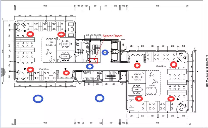
As shown below in the figure, it illustrates the floor plan of an Internet company is illustrated with three floors. Each floor has approximately 100 workstations. Each workstation uses 2-3 devices, including smartphones, app testing devices, and office laptops. This setup results in an estimated 250 devices per floor.
The company requires wireless coverage for all office phones and laptops, with seamless roaming across all areas. To ensure strong signal coverage, the administrator deployed access points (APs) to cover all workstations (shown as red dots) and installed additional APs for outdoor terraces, elevator halls, and corridors (shown as blue dots).
Deployment Outcome and Challenges
After deployment:
- Wi-Fi signal strength exceeded -50dBm in all areas on a single floor.
- Nighttime tests showed maximum ISP bandwidth speeds.
- However, daytime user experiences were unexpectedly poor, with employees complaining about slow network speeds.
Despite these complaints, bandwidth utilization on the ISP router remained low. So, what went wrong?
Signal Strength vs. Signal-to-Noise Ratio (SNR)
While signal strength (dBm) is a basic requirement for guaranteed service, strong signal quality does not necessarily equate to good user experience. Signal strength must be translated into SNR (signal-to-noise ratio, the difference between signal and noise, measured in dB), which significantly impacts user experience.
Understanding SNR: Imagine speaking at home in a quiet environment versus shouting at a pop concert. Even with strong signals (loud voice), high background noise makes communication difficult. Similarly, in Wi-Fi networks, even if the signal strength is strong, high noise levels can hinder performance.
High-Density Deployment Challenges
The company deployed a high-density network across all three floors without conducting RF power and channel planning, which involves adjusting the transmit power of access points and strategically assigning non-overlapping channels to minimize interference and optimize performance. This oversight caused significant issues:
- Interference Sources:
- Non-Wi-Fi devices (e.g., microwave ovens, Bluetooth phones).
- Co-frequency networks, including frequency-hopping wireless devices and radar interference.
- Nearby “Friend Wi-Fi Networks.”
- Wi-Fi-Specific Interference:
- Inter-AP interference.
- Inter-terminal interference.
- Terminal-to-AP interference, exacerbated in multi-user, multi-path environments.
Key Takeaways
To ensure optimal wireless performance:
- Conduct a Comprehensive Site Survey:
- Use professional tools to analyze RF power, channel allocation, and noise levels.
- Plan for Channel and Power Management:
- Avoid overlapping channels and excessive RF power settings.
- Account for Environmental Factors:
- Identify potential interference sources (e.g., neighboring networks and devices).
- Implement Network Optimization:
- Regularly monitor and adjust configurations based on real-time network performance.
By addressing these critical areas, the company could transform its wireless network from a problematic setup into a high-capacity, reliable solution. Key actions include:
- Conducting a comprehensive site survey to analyze RF power, channel allocation, and noise levels.
- Planning channel and power management to avoid overlapping and interference.
- Accounting for environmental factors such as neighboring networks and devices.
- Implementing ongoing network optimization based on real-time performance data.
How to Plan Deployment
When deploying a wireless LAN (WLAN), the key objectives are to maximize channel multiplexing efficiency and air interface utilization. These goals help reduce media contention and radio frequency (RF) interference. Achieving this requires careful planning and design. This section outlines a step-by-step approach for efficient deployment.
Plan Efficient Channel Multiplexing and Minimize Channel Sharing
Channel multiplexing involves the use of non-overlapping channels for coverage, aiming to reduce co-channel interference. Since the available wireless spectrum is limited, channels or channel combinations must often be reused to achieve complete wireless network coverage in enterprise environments.
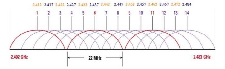
- 2.4 GHz Band: In the United States, only three non-overlapping channels (CH1, CH6, CH11) are available.
- 5 GHz Band: More abundant, typically offering nine non-overlapping channels: CH36, CH40, CH44, CH48, CH149, CH153, CH157, CH161, and CH165.
- 6 GHz Band: The newest addition, offering even greater spectrum availability with up to 59 non-overlapping channels (subject to regional regulatory approval). This band is particularly suited for high-density deployments, providing minimal interference and supporting modern Wi-Fi 6E and Wi-Fi 7 standards.
In high-density deployments requiring many access points (APs) to serve a large number of clients, efficient channel multiplexing becomes particularly challenging. The limited resources of the 2.4 GHz spectrum make it unsuitable for such scenarios, often necessitating the deactivation of the 2.4 GHz band to improve user experience. The 5 GHz band, with its richer spectrum, is typically utilized, as it offers higher capacity, reduced interference, and better support for modern wireless technologies. Additionally, the 6 GHz band has emerged as a key player, providing even greater capacity with up to 59 non-overlapping channels, minimal interference, and robust support for Wi-Fi 6E and Wi-Fi 7 standards, making it highly suitable for high-density and future-ready deployments.
Example of Channel Multiplexing
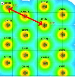
The diagram demonstrates how AP1 and AP2 utilize the same CH42 channel (center frequency of an 80MHz channel). If AP1 and AP2 are within detection range of each other, they share the same channel and cannot transmit simultaneously. However, when their coverage does not overlap, they operate independently, enabling simultaneous data transmission for their respective clients without interference.
Best Practices for Efficient Channel Multiplexing in High-Density Deployments
- Control AP Transmit Power:
- Keep transmit power at a minimal level sufficient to cover the planned cell size.
- Disable Low Data Rates:
- Deactivate legacy data rates (e.g., 1 Mbps, 2 Mbps, 5.5 Mbps, 11 Mbps from 802.11b) to shrink cell size and limit management frames to higher rates, such as 18 Mbps or 24 Mbps. Note: This approach is suitable only for high-density scenarios without distant client connections.
- Use Physical or Natural Barriers:
- Leverage structures (e.g., thick concrete walls, elevator shafts, pillars) or natural partitions (e.g., large landscapes) to control RF signal propagation and attenuate signals in unintended directions.
- Directional Antennas:
- Use directional antennas instead of omnidirectional ones to focus signal coverage and reduce co-channel interference.
Improve Air Interface Efficiency in a Single-Channel Coverage Cell
Enhancing Air Interface Efficiency
Air interface efficiency focuses on establishing high data rate connections between clients and APs. The modulation and coding scheme (MCS) used for communication adapts dynamically based on the client’s distance from the AP and environmental factors. Clients farther from the AP typically experience lower data rates due to increased redundancy requirements.
Strategies to Improve Efficiency:
- Optimize AP Placement:
- Analyze client behavior and locations to position APs where clients can stay as close as possible, ensuring strong signal strength and higher data rates.
- Enable Band Steering:
- Encourage dual-band clients to connect to the 5GHz band or 6GHz for higher throughput and reduced congestion.
- Limit Client Connection Distance:
- Consider policies to restrict connections from distant clients, ensuring that connected clients maintain high data rates.
- Update Firmware:
- Use the latest firmware for APs to enable advanced features such as dynamic channel selection, transmit beamforming, and MU-MIMO for enhanced efficiency.
Additional Tools and Features for Deployment
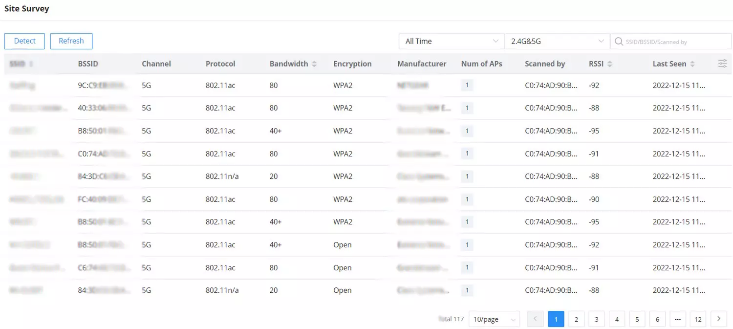
- Site Survey Tool: Grandstream’s GDMS Networking cloud platform or on-premise GWN Manager includes a powerful Site Survey tool. It scans wireless signals in the surrounding environment and provides comprehensive information such as channel usage, bandwidth, RSSI, encryption type, and more. For example, in a recent deployment in a high-density office environment, the Site Survey tool identified overlapping channels and allowed the team to adjust AP placements, optimizing coverage and minimizing interference. This tool is essential for identifying optimal AP placement and minimizing interference. For more info, please refer GDMS Networking – User Guide.
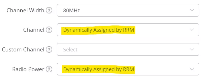
- Radio Resource Management (RRM): Grandstream GWN access points feature Dynamic Channel and Radio Power assignment using RRM. This feature allows APs to dynamically adjust their channels and power levels to avoid channel overlap and minimize interference, ensuring optimal network performance. For more info, please refer GWN76xx User Manual.
Additional Tips for Deployment
- Monitor Network Performance: Continuously evaluate performance metrics to proactively identify and address potential issues before they impact performance, ensuring consistent and efficient network operation.
- Plan for Future Expansion: Account for potential growth in client devices and network usage when planning the deployment.
Significance of Radio Signal Parameter
Wireless networks are an essential part of daily life, work, and entertainment, as reliance on them continues to grow for both personal and professional activities. This increasing dependence highlights the need to address the unique performance challenges of wireless networks. However, users often expect WLAN wireless networks to match the stability of wired networks, which is not always the case. Evaluating wireless network performance differs significantly from evaluating wired network performance.
For instance, when a laptop is connected to a wired network switch via a network cable, the data connection rate between the links might be 1000 Mbps, and performance testing tools usually yield consistent results with over 90% physical layer efficiency. In contrast, with a wireless connection to an access point (AP), the link’s data rate might show as 1300 Mbps, but throughput tests often reveal much lower efficiency, around 65% in a one-to-one connection between the AP and a client. As the number of connected clients increases, aggregate throughput further declines. Several factors contribute to this discrepancy:
- Unstable and unreliable air media: For example, wireless signals can be affected by physical obstacles such as walls, furniture, or even human bodies, leading to fluctuations in signal quality.
- CSMA/CA mechanism for access, leading to data collisions and retransmissions.
- MAC layer acknowledgment mechanisms, resulting in inevitable data retransmissions.
- Compatibility requirements with older devices, increasing physical layer overhead.
These differences highlight the challenges of achieving reliability in wireless networks and emphasize the importance of proper planning, design, and maintenance, which differ significantly from wired networks.
Key Parameters for Wireless Deployment
- SNR (Signal-to-Noise Ratio)
For wireless clients, SNR is the most critical indicator of performance because it determines the clarity of the signal in relation to background noise. In simple terms, a higher SNR means the signal is strong and clear, while a lower SNR indicates the signal is weak and may be overwhelmed by noise, leading to poor performance. SNR is the difference between the received signal strength and the noise floor. A higher SNR indicates better signal quality.
- Example 1: Received signal strength = -65 dBm, noise floor = -92 dBm. SNR = 27 dB.
- Example 2: Received signal strength = -60 dBm, noise floor = -80 dBm. SNR = 20 dB.
In this case, even though the second signal is stronger, the poorer SNR results in inferior signal quality.
SNR Guidelines:
- SNR > 40 dB: Excellent signal quality, highest data connection rates.
- SNR 25-40 dB: Good signal quality, high data connection rates.
- SNR 15-25 dB: Acceptable signal quality, good data connection rates.
- SNR 10-15 dB: Fair signal quality, low data connection rates.
- SNR < 10 dB: Poor signal quality, unreliable connection.
Note: SNR affects channel bandwidth, spatial streams, and modulation methods. For instance, using an 80 MHz channel width requires a higher SNR than a 20 MHz channel.
To establish high data connection rates:
- 20 dB SNR is needed for 802.11a/g.
- 25 dB SNR is needed for 802.11n.
- 30+ dB SNR is needed for 802.11ac.
Improving SNR
Increasing the AP’s transmit power is not always effective due to limited non-overlapping channels. Instead, reducing noise is a better approach:
- Record neighboring AP locations, channel distribution, and coverage areas.
- Plan installation locations, channel frequencies, bandwidth, and transmit power to avoid co-channel and adjacent-channel interference.
- Use spectrum scanning tools to identify and eliminate interference from non-WiFi devices.
- Conduct post-deployment surveys and optimize as needed.
Survey tools, such as those available in Grandstream’s GDMS or GWN Manager, allow you to measure RSSI to assess signal strength. For evaluating SNR, additional tools can be used to visualize and calculate this parameter, providing deeper insights into signal quality and performance.
- Channel Utilization
Channel utilization measures the busyness of the RF spectrum and the availability of the AP channel. It is expressed as a percentage:
- < 40-50%: Acceptable for most applications.
- > 70%: Overcrowded channel.
Channel utilization reflects the combined effects of co-channel interference, adjacent-channel interference, and non-WiFi interference.
Factors Affecting Channel Utilization:
- Wi-Fi Client Data Transmission
- Larger data packets occupy the channel longer.
- Slower transmission rates increase air time usage.
- Co-Channel Interference
- APs on the same channel compete for usage, limiting throughput. Proper planning can reduce interference.
- Adjacent Channel Interference
- Overlapping channels (e.g., CH1 and CH4 on 2.4 GHz) increase background noise and degrade performance.
- Non-WiFi Interference
- Sources include Bluetooth devices, microwave ovens, DECT phones, and surveillance cameras.
Measuring Channel Utilization
Channel utilization helps assess Wi-Fi network performance and detect congestion. With Grandstream GWN Access Points, this data can be retrieved and analyzed directly through the GWN’s SSH-based menu system. This section explains how to measure and interpret channel utilization for 2.4 GHz, 5 GHz, and 6 GHz bands.
Steps to Measure Channel Utilization
Step 1: SSH Login
- Open your preferred SSH client (e.g., PuTTY) and enter the GWN device’s IP address.
- Use the WebUI credentials to log in.
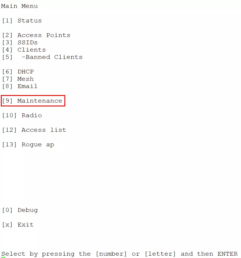
Step 2: Navigate to the “Maintenance” Menu
- After logging in, the main menu will display various options.
- Type [9] Maintenance and press Enter to open the Maintenance menu.
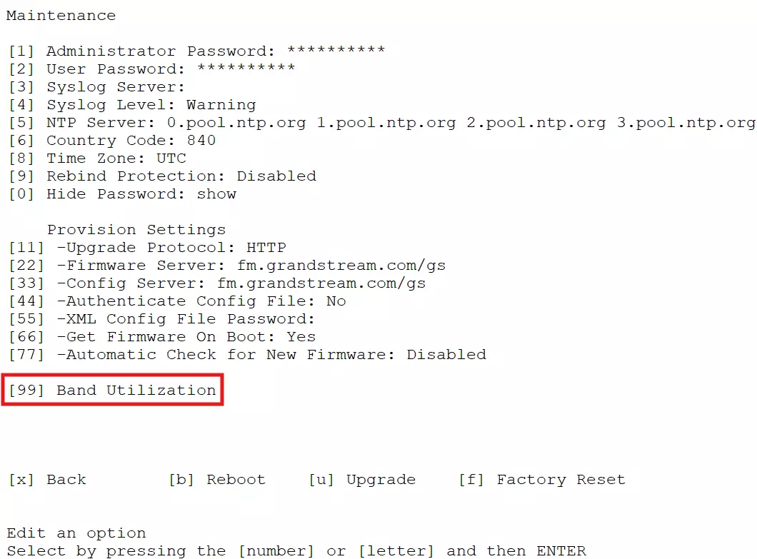
Step 3: Access Band Utilization
- In the Maintenance menu, select [99] Band Utilization and press Enter.
- The system will scan and analyze utilization data for all supported bands (e.g., 2.4 GHz, 5 GHz, and 6 GHz).
Understanding Band Utilization Output
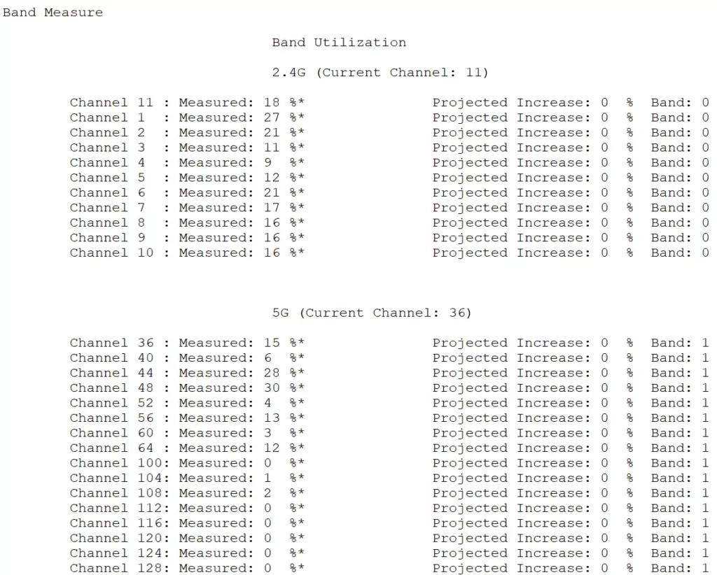
The output will display utilization metrics for each channel within the supported bands:
2.4 GHz Band
- Current Channel: The channel currently used by the access point.
- Measured Utilization (%): Percentage of channel activity. Lower values indicate less congestion.
- Projected Increase (%): Predicted increase in utilization based on current trends. This helps anticipate future congestion.
Example:
2.4G (Current Channel: 11)
Channel 11 : Measured: 18 %
Channel 1  : Measured: 27 %
Channel 6  : Measured: 21 %
...
5 GHz Band
- Current Channel: The channel currently used by the access point.
- Measured Utilization (%): Percentage of channel activity.
- Projected Increase (%): Predicted increase in utilization.
Example:
5G (Current Channel: 36)
Channel 36 : Measured: 15 %
Channel 40 : Measured: 6 %
Channel 44 : Measured: 28 %
...
Reading and Interpreting the Output
- Identify High Utilization Channels: Look for channels with measured utilization above 60% (high utilization, performance may begin to degrade), and treat channels above 80% as likely congested. Utilization in the 20%–30% range is generally optimal, and 30%–60% is typical in enterprise/high-density deployments.
- Select Low Utilization Channels: Opt for channels with the lowest measured utilization for better performance.
- Understand Projected Trends: Channels with high projected increases may experience congestion soon. Plan to avoid them when possible.
Quick Reference:
- Channels with utilization below 20% are optimal because they experience less interference, allowing for higher speeds and more reliable connections.
- Channels with utilization above 50% should generally be avoided.
Reducing High Channel Utilization
- Reduce the Number of SSIDs
- Each SSID adds overhead. For example, one SSID at 1 Mbps consumes about 3% of channel bandwidth.
- Turn Off Low Data Rates
- Forcing clients to use higher data rates reduces air time consumption and channel utilization.
- Access Control
- Limit client numbers and restrict bandwidth-intensive applications like P2P software.
- Adjust AP Coverage Areas
- Reduce AP transmit power or forbid low-speed management frames to decrease overlap and interference.
- Plan Channel Reuse
- Efficient channel planning avoids co-channel and adjacent-channel interference.
- Eliminate Illegal Devices
- Use spectrum scanning to identify and remove non-WiFi interference.
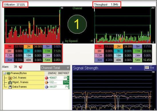
By following these strategies, you can optimize wireless network performance and ensure a better user experience. Focus on regular monitoring, using the appropriate tools to measure network health, and adjusting configurations as needed to maintain high performance.
Impact of Client Performance
When designing, deploying, and verifying wireless networks, we often focus on the capabilities of the wireless network, particularly the Access Points (APs), and overlook an equally critical component: the wireless client. Clients significantly impact the performance and reliability of a network by influencing throughput, latency, and overall connection stability. Factors such as client hardware limitations, transmission power, and roaming behaviors play a critical role in determining how well the network performs under real-world conditions. Thus, understanding their capabilities and behaviors is essential for optimal network design and deployment.
Key Client Capabilities to Consider
- Hardware and Connectivity Features:
- Built-in network card vs. external USB adapters.
- Support for 2.4 GHz, 5 GHz, and 6 GHz bands.
- Compatibility with Wi-Fi 6, Wi-Fi 6E, and Wi-Fi 7 standards, which promise higher speeds, lower latency, and better performance in congested environments by utilizing advanced technologies like multi-link operation and 320 MHz channel widths.
- Supported 5 GHz and 6 GHz channels.
- Transmission and Reception Performance:
- Client transmission power and receiving sensitivity.
- Support for 40 MHz, 80 MHz, or even 160 MHz channel widths.
- Number of antennas for sending and receiving signals (MIMO capabilities).
- Supported spatial streams and antenna gain.
- Antenna design and installation position.
- Scanning and Security:
- Number of channels the client can scan.
- Support for advanced encryption protocols (e.g., WPA3).
- Software and Configuration:
- Algorithm for selecting AP during initial connections.
- Roaming decision algorithms for seamless transitions between APs.
Updated Client Behavior Considerations
Modern clients employ sophisticated algorithms for:
- Selecting the best AP based on factors like signal strength, load balancing, and channel interference. For example, a client device may prioritize connecting to an AP with slightly lower signal strength but lower network congestion, optimizing the overall connection quality.
- Deciding when and how to roam between APs to maintain a stable connection.
Importance of Client Transmission Power
A crucial factor during Wi-Fi deployment planning is the client’s transmission power. Mobile devices, such as smartphones and tablets, often prioritize low transmission power to conserve battery life. Additionally, their compact size limits antenna performance. These limitations result in small antenna gains and reduced transmission power, as shown in the table below:
Device Type | Typical EIRP 2.4GHz (dBm) | Typical EIRP 5GHz (dBm) | Typical EIRP 6GHz (dBm) |
Smartphone (Wi-Fi 6) | 17-19 dBm | 16-18 dBm | – |
Smartphone (Wi-Fi 6E) | 17-19 dBm | 16-18 dBm | 15-17 dBm |
Tablet | 18-20 dBm | 17-19 dBm | 16-17 dBm |
Laptop | 20-22 dBm | 19-21 dBm | 18-20 dBm |
High-Performance Device | 21-23 dBm | 20-22 dBm | 19-21 dBm |
Typical EIRP for Common Client Devices
Challenges of Mismatched Transmission Power
Wi-Fi systems are bidirectional. A mismatch between the AP and client’s transmission power can cause uplink communication failures, even if the downlink signals from the AP are strong. For example:
- An AP’s powerful signal may reach the client effectively, but the client’s weaker signal may not reach the AP with sufficient signal-to-noise ratio (SNR).
- This mismatch impacts Layer 2 communication, such as acknowledgment (ACK) messages. If ACK packets fail, the entire communication can fail, leading to packet drops or application interruptions.
This issue is especially problematic for real-time applications (e.g., voice and video), where uplink and downlink traffic must remain balanced to prevent interruptions.
Balancing Uplink and Downlink
To avoid issues:
- Avoid increasing AP transmission power as the first response to connectivity issues. Higher AP power can:
- Increase interference across the network.
- Cause clients to become “sticky” to a distant AP, disrupting optimal roaming behavior.
- Instead, analyze client behavior, roaming areas, and the building’s physical partitions. Set AP transmission power as low as possible while still providing adequate coverage.
Planning for Optimal Deployment
Proper planning and analysis of client behavior and capabilities are essential for effective network deployment. For example, in a large office environment, understanding that employees use a mix of high-performance laptops and older smartphones can help design AP placement and transmission power settings to ensure coverage and performance are optimized for all devices. Key steps include:
- Classify Target Wi-Fi Clients:
- Identify client types (e.g., smartphones, tablets, laptops) and their power levels.
- Determine client behavior (e.g., roaming patterns, supported bands).
- Ensure Compatibility and Updates:
- Upgrade client drivers to vendor-recommended versions when possible.
- Encourage the use of dual-band or tri-band clients (supporting 2.4 GHz, 5 GHz, and 6 GHz).
- Test and Optimize:
- Evaluate client roaming capabilities in the deployment environment.
- Validate coverage and performance for real-world scenarios, including both high- and low-powered clients.
Future Considerations with Wi-Fi 6E and Wi-Fi 7
Wi-Fi 6E’s 6 GHz band and Wi-Fi 7 advancements add new factors to consider:
- 6 GHz Support: Clients must support this band for reduced interference and higher throughput.
- Channel Allocation: Ensure proper channel planning to leverage the wider 160 MHz and 320 MHz channels.
- Higher Spatial Streams: Future clients and APs may support up to 16 spatial streams, further improving throughput for high-performance applications.
By carefully considering these factors and adapting deployment strategies, you can ensure a balanced, high-performance wireless network that meets the needs of all client devices, both current and future.