The WP856 is a high-end mobile computing device designed for users on the go who need access to reliable mobile scanning software. This powerful, portable device comes equipped with integrated dual-band 802.11a/b/g/n/ac/ax, 2.4G/5G Wi-Fi support, advanced antenna design, roaming support, and integrated Bluetooth for pairing with headsets and mobile devices. With excellent data scanning performance for 1D and 2D barcodes, as well as NFC support for instant data communication, this device helps increase productivity by providing instant access to critical and real-time information. The WP856 is equipped with a 20-hour talk time, a 5.5-inch HD touch screen, and an IP65 dustproof, waterproof, and drop-safe height of 1.5 meters. This device is long-lasting and durable for any environment or user on the go. The WP856 is ideal for deployment scenarios such as healthcare facilities, retail locations, building security, logistics environments, and more.
PRODUCT OVERVIEW
The following table contains the major features of the WP856:
6 SIP accounts, 6 lines
Android 13 OS, supports custom Android apps
IP65 dustproof and waterproof, Drop-safe from 1.5 meter height.
Dual-band Wi-Fi with efficient antenna design and fast roaming support
Rechargeable 5000mAh battery, 20 hour talk time, 200 hour standby; USB Type-C port, supports fast charging
Excellent data capture performance on 1D and 2D barcodes, Supports NFC for data communication.
WP856 Features at a Glance
Technical Specifications
The following table summarizes all the technical specifications, including the protocols/standards supported, voice codecs, telephony features, languages, and upgrade/provisioning settings for the WP856.
Support for G.711μ /a, G.729A/B, G.722 (wide-band), iLBC, Opus, in-band and out-of-band DTMF (In audio, RFC2833, SIP INFO),VAD, CNG, AEC, PLC,AJB,AGC, ANS
Video Codecs and Capabilities
H.264 BP/MP/HP, video resolution up to 1080p, frame rate up to 30 FPS, bit rate up to 20Mbps, 3-way video conference (1080p at 30 FPS), anti-flicker capability, auto focus and auto exposure
Customizable Function Keys
Customizable button for scan, push-to-talk, panic call, and other related functions
Bluetooth
Yes, Bluetooth 5.2, supports Bluetooth Low Energy (BLE)
ITF 14, Matrix 2 of 5, Industrial 25, Standard 2 of 5, Code39, ISSN, ISBN, CodaBar, Code93, Code 11, Plessey, MSI Plessey, RSS
2D: Aztec, Composite, CS Code, Maxicode, Micro PDF, Micro QR, PDF 417, QR Code, Data Matrix, DotCode.
Near-Field Communication
(NFC)
13.56MHz RFID
ISO14443A/B, ISO15693,ISO18000-3, MIFARE, FeliCa RF, NFC Forum Type 1-4 Tag
Telephony Features
Hold, transfer, forward, 6-line audio conference, downloadable phonebook (XML, LDAP, up to 1000 items), call waiting, call log (up to 1000 records), auto answer, click-to-dial, flexible dial plan, hot desking, personalized music ring-tones and music on hold, server redundancy and fail-over, push-to-talk
Security
User and administrator level passwords, MD5 and MD5-sess based authentication, 256-bit AES based secure configuration file, SRTP, TLS, HTTPS, 802.1x media access control
HD Audio
Yes, both on handset and speakerphone, supports wideband audio
QoS
802.11e and Layer 3 (ToS, DiffServ, MPLS) QoS
Multi-language
English, Arabic, Chinese, Czech, Dutch, German, French, Hebrew, Italian, Japanese, Polish, Portuguese, Russian, Spanish, Turkish, and more
Upgrade/Provisioning
Firmware upgrade via HTTP/HTTPS, mass provisioning using TR-069 or encrypted XML configuration file, manual upload
Display
5.5 inch (1440×720) multi-point capacitive touch screen; Up to 450 NIT (brightness), display backlight adjusts automatically
Camera
Rear camera: 13MP, auto focus, with LED flashlight Front camera: 5MP, fixed focus
GPS
Supports GPS, Galilieo, and Beidou
SD Card
Supports Micro SD cards (up to 256GB)
AC Adapter
Quick charger (Output: 5V-3A/9V-2A/12V-1.5A Input: AC 100~240V, 50/60Hz)
Peripherals
Volume button(+,-), Push-To-Talk Button, Left/Right Scan Button, Power button, Vibration motor, Multi-color LED
Battery
5000mAh 3.85V rechargeable battery; 200 hours standby time and 20 hours talk time (the battery can be removed and replaced)
Microphone and Speaker
Dual microphones, HD speaker and speakerphone (1W)
Headset dimensions: 161x 74 x 15mm Handset weight: 0.28KG
Temperature and Humidity
Operating Temperature: -20 °C to 50 °C (-4°F to 122°F); Charging Temperature: 5-40 °C (41°F to 104°F); Storage Temperature: -20 °C to 60 °C (-4°F to 140°F);
Package Contents
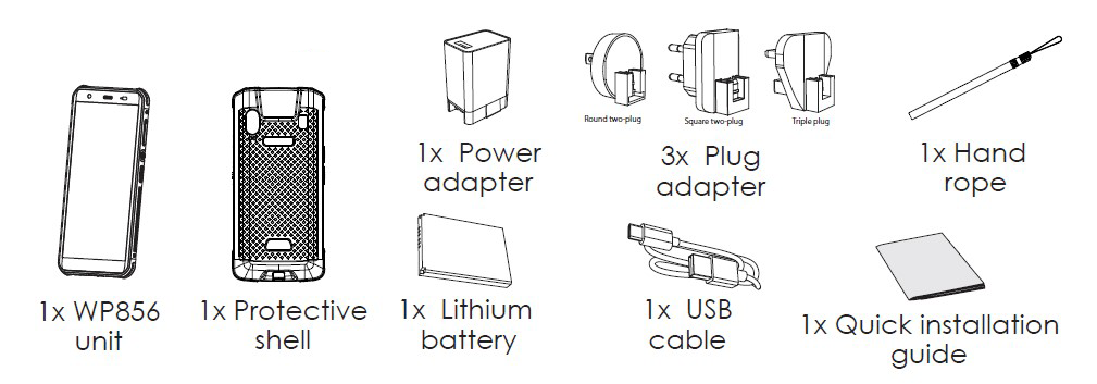
Handset unit, power adapter, quick start guide, hand rope, protective shell, 3x plug adapter, Lithium battery, USB cable
Ruggedization and Protection
Dropsafe up to 1.5m height when dropped on to concrete Casing: IP65-rated waterproof and dustrproof
This chapter provides basic installation instructions, including the packaging contents list and information for obtaining the best performance with the WP856.
Equipment Packaging
WP856
1x WP856 Unit
1x Protective shell
1x Power adapter
1x Lithium Battery
1x Round two-plug
1x Square two-plug
1x Triple plug
1x Hand rope
1x Quick Installation Guide
Equipment Packaging
WP856 Package Content
Important
Check the package before installation. If you find anything missing, contact your system administrator.
Setting up the WP856
Charging the Battery
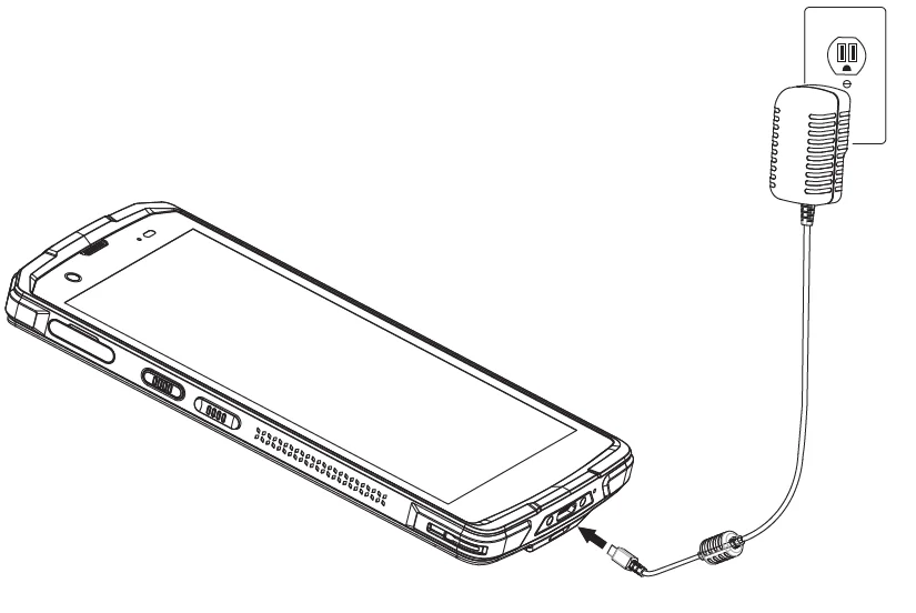
Connect the device to a power outlet using the included AC adapter and cable as shown in the figure:
Charging Station
Note
Please charge the battery fully before using the device for the first time. (For more information about the battery, please refer to Battery Information.
Battery Information
Technology: Rechargeable Li-ion Battery
Capacity: 5000mAh
Standby time: up to 200 hours
Talk time: up to 20 hours of active talk time
To get the best performance from your WP856, we recommend using the original battery provided in the package. The specifications may differ depending on the age and capacity of the battery used.
Note
The WP856 device generates a warning tone when the device’s battery level becomes 15% and 5%.
WP856 auto boots up once placed on the charger when the device is powered off abnormally (Battery too low, battery removed suddenly, etc).
WP856 Handset Buttons Description
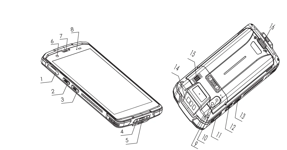
The WP856 enhances communication and combines usability and scalability in industries such as warehousing, catering, retail, and factories. The following screenshot describes the WP856 LCD screen and the main hardware components.
WP856 Description
The following table describes the WP856 keypad keys.
Key
Description
1
TF card
Slot for inserting a TF (TransFlash) or microSD card for additional storage.
2
PTT Button
Programmable key for quick access to specific functions or applications.
3
Left scan key
Button for initiating barcode or QR code scanning.
4
Dock connector
Interface for connecting the device to a docking station for charging or data transfer.
5
Charging port
Port for connecting a charger to power the device.
6
Front camera
Camera located on the front for taking selfies or video calls.
7
Earpiece
Speaker for listening to phone calls.
8
LED indicator
Light to signal notifications, charging status, or other alerts.
9
Camera
Rear camera for taking photos and videos.
10
Flashlight
LED light for illumination, used with the rear camera.
11
Volume keys
Buttons to increase or decrease the audio volume.
12
Power buttom
Button to power on/off the device or wake it from sleep mode.
13
Right scan key
Button for initiating barcode or QR code scanning.
14
Scan window
The area where the device scans barcodes or QR codes.
15
Speaker
Speaker for audio output, such as media playback or speakerphone calls.
16
Battery back cover latch
Mechanism to release the back cover to access the battery.
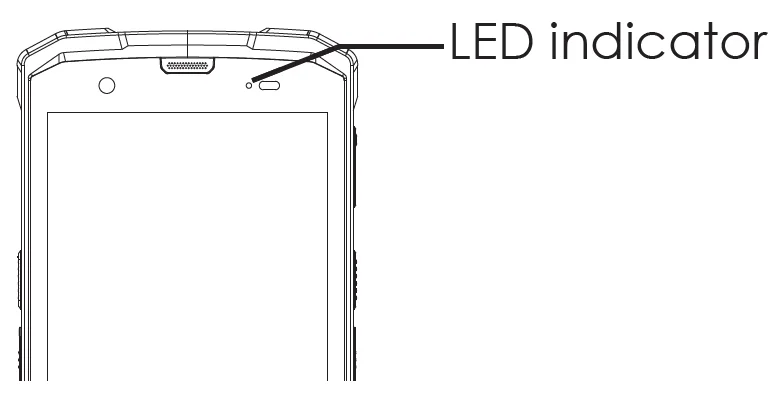
WP856 LED Status
The WP856 device has the following LED indications:
LED indicators
Solid Green
Charged (full)
Solid Red
Charging (not full)
Red Blinking
Low battery alarm
Blue Blinking Once:
Decode successfully
LED OFF
Normal
WP856 LED Status
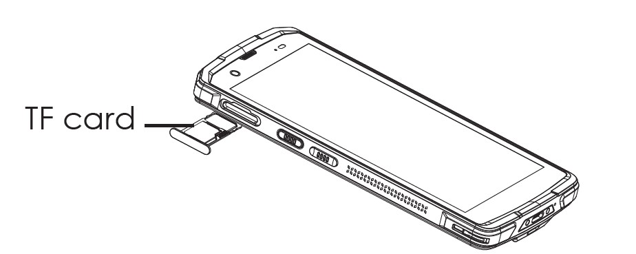
Installing TF Card
The Transfer-Flash (TF) Card is used for additional data storage on the WP856 device. Please follow the steps below for installation:
TF Card Reader
Find the TF card slot on the left side of the collector/terminal and pull out the cardholder.
Put the TF card into the cardholder and push the cardholder inside.
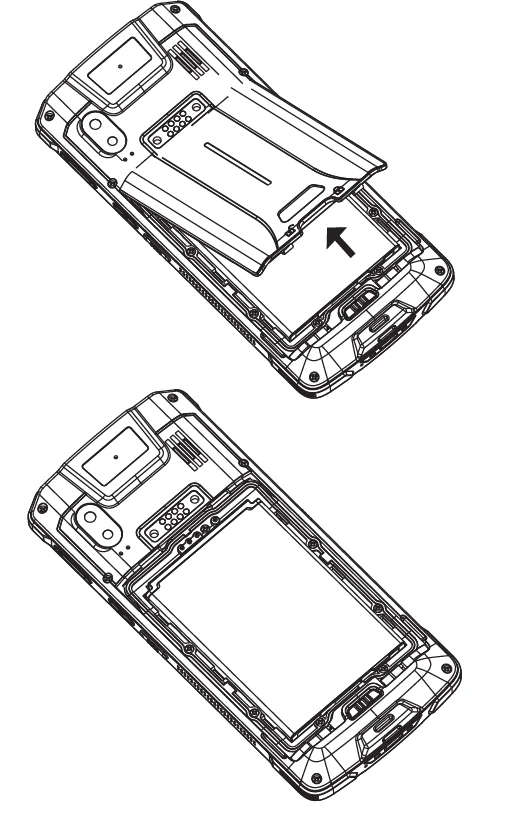
Battery Installation and Removal
Installing the Battery
Unlock the battery back cover and remove the back cover.
Attach the top metal contacts of the battery to the metal contacts inside the body and press down firmly.
Removing the Battery
Press and hold the power button for 2 seconds, then click the shutdown option on the screen, then unlock the battery back cover to open the back cover.
Remove the battery.
Scanning Barcode
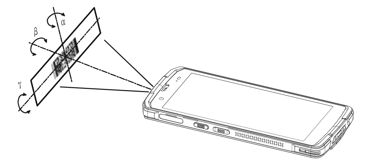
The WP856 mobile computing device allows users to scan 1D and 2D barcodes using an integrated scan window at the top of the phone. It uses NFC technology to scan a barcode using the WP856 device, adjust the scan angle and the distance between the device and the target barcode to make them fall into the following ranges:
Point the Device’s focus lamp at the center of the barcode.
Move the Device until you find the appropriate scan distance.
Optimum scan angles:
Skew(α)<45° (0° preferably)
Pitch(γ )<45° (5°- 20° preferably)
Roll(β)=0° – 360°
Scanning Barcode
Obtain WP856 IP Address
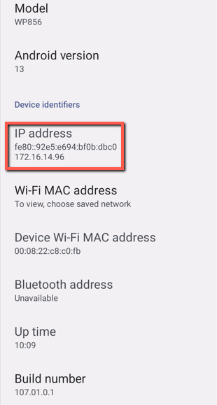
To know which IP address is assigned to your WP856, please follow the steps below:
After unlocking, sliding the screen up will open the operation menu.
Go to GS Settings → Device information → Network status to check the IP address assigned to WP856.
Both the IPv4 and IPv6 addresses of the device will be displayed.
Display IP Address
WP856 WEB GUI ACCESS CONFIGURATION
The WP856 can be configured using:
Web GUI embedded on the WP856 using the PC’s web browser.
Configuration Menu using the WP856 touchscreen.
Note: From the Web GUI, you can configure all the functions supported by the WP856; while there will be some limitations when configuring the WP856 mobile computing device from the touchscreen.
Configuration via Web Browser
The WP856 embedded Web server responds to HTTP/HTTPS GET/POST requests. Embedded HTML pages allow a user to configure the WP856 through a Web browser such as Google Chrome or Mozilla Firefox.
Note: Please note thatMicrosoft’s IE 9 and below are not supported; also, the records from the web cannot be played with IE10, Edge, and Safari. We highly recommend using Google Chrome or Mozilla Firefox.
Accessing the Web UI
Access GS Settings > Advanced Settings to set “Disable web login” to “No”.
Go to GS Settings > Device information > Network Status to check the IP address assigned to WP856.
Type the phone’s IP address in your PC browser.
Enter the admin’s username and password to access the configuration menu. (The factory default username is “admin” and the password is a randomly generated string that is printed on a label in the battery compartment of the device.)
Note
The computer must be connected to the same sub-network as the WP856. This can be easily done by connecting the computer to the same hub or switch as the WP856.
If the ‘Disable web UI access’ parameter is enabled under Advanced settings → System Security, web UI access will be disabled.
The web GUI can also be accessed through the GDMS when the device is added to the GDMS Unified Communication cloud platform.
To do that, access VoIP Device menu on the GDMS, then click on the three-dot menu then click Remote Access to Web UI.
GDMS VoIP Devices
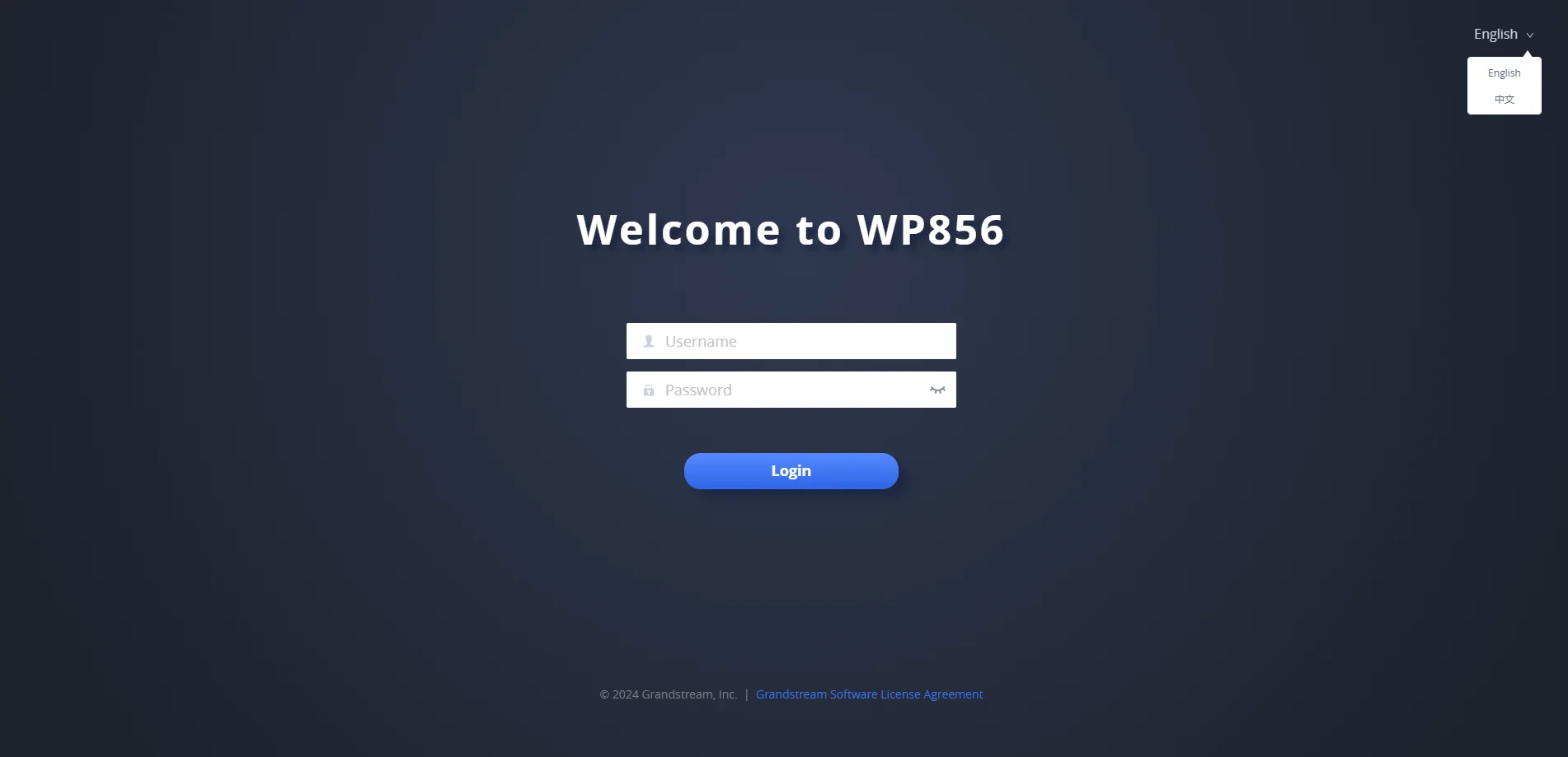
Web GUI Languages
The WP856 web GUI supports English and Chinese languages.
Users can select the displayed language on the web GUI login page or at the upper right of the web GUI after logging in.
WP856 Web GUI Language
Saving the Configuration Changes
When changing any settings, always submit them by pressing the Save and Apply buttons. If using the Save button, after making all the changes, click on the Apply button at the top of the page to submit.
Web UI Access Level Management
There are two default passwords for the login page:
User Level
Username
Password
Web Pages Allowed
End User Level
user
123
Only Status, Phone Settings, Network Settings, System Settings, Application settings, and Maintenance settings with limited access
Administrator Level
admin
Found on a sticker, on the device
All pages
Changing User Level Password
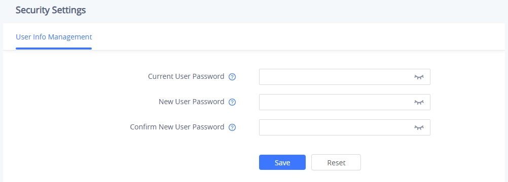
Go to System Settings →Security Settings.
In User Info Management, locate the user password section:
Type in the admin password in the CurrentUser Password field.
Type in your new user password in the New User Password field.
Type in the same password again in the Confirm New User Password field.
Press the Save and Apply buttons to save your new settings.
User Level Password
Note
For the password requirements, enter 8 to 32 characters, including at least 1 number, 1 uppercase letter, 1 lowercase letter and 1 special character.
Changing HTTP / HTTPS Web Access Port
Access the Web GUI of your WP856 using the admin’s username and password.
Press Login to access your settings.
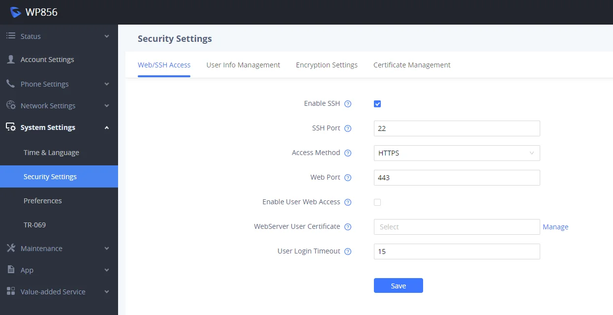
Go to System Settings → Security Settings.
In the Web/SSH Access page, select the access method depending on the desired protocol (HTTP or HTTPS)
Locate the HTTP / HTTPS Web Port field and change it to your desired/new HTTP / HTTPS port.
Press the Save and Apply buttons to save your new settings.
Note
After modifying the connection method or port, the web GUI will be automatically logged out and redirected to the new address.
By default, the HTTP port is 80 and HTTPS is 443.
SSH access is enabled by default and uses the default port 22.
WebSSH access
BASIC OPERATIONS
WP856 Home Screen
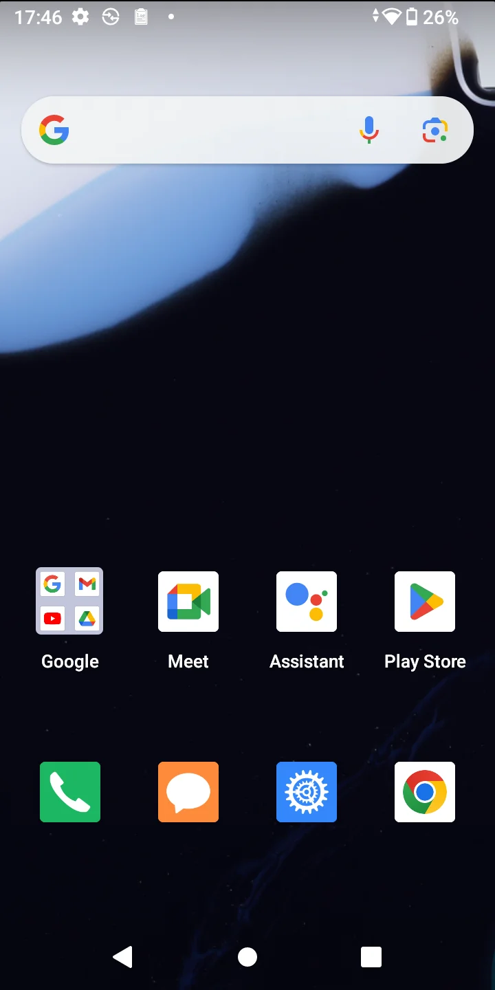
The WP856 home screen features a customizable launcher that allows users to add and configure various widgets tailored to different use cases. By default, the launcher displays a list of installed applications for easy access.
Launcher
WP856 Application Menu
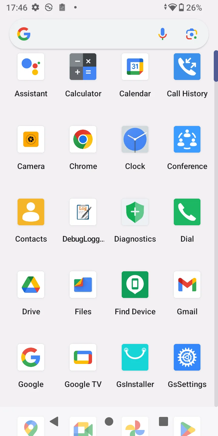
The WP856 comes with a list of preinstalled applications such as Camera, Clock, Contacts, DebugLogging, Diagnostics, and more, contributing to various use cases.
To access the applications menu, swipe up on the home screen.
Applications Menu
Connecting WP856 to a Wi-Fi network
Manual Connection
The WP856 supports dual-band 802.11a/b/g/n/ac/ax Wi-Fi. Please refer to the following steps to connect your WP856 to the Wi-Fi networks:
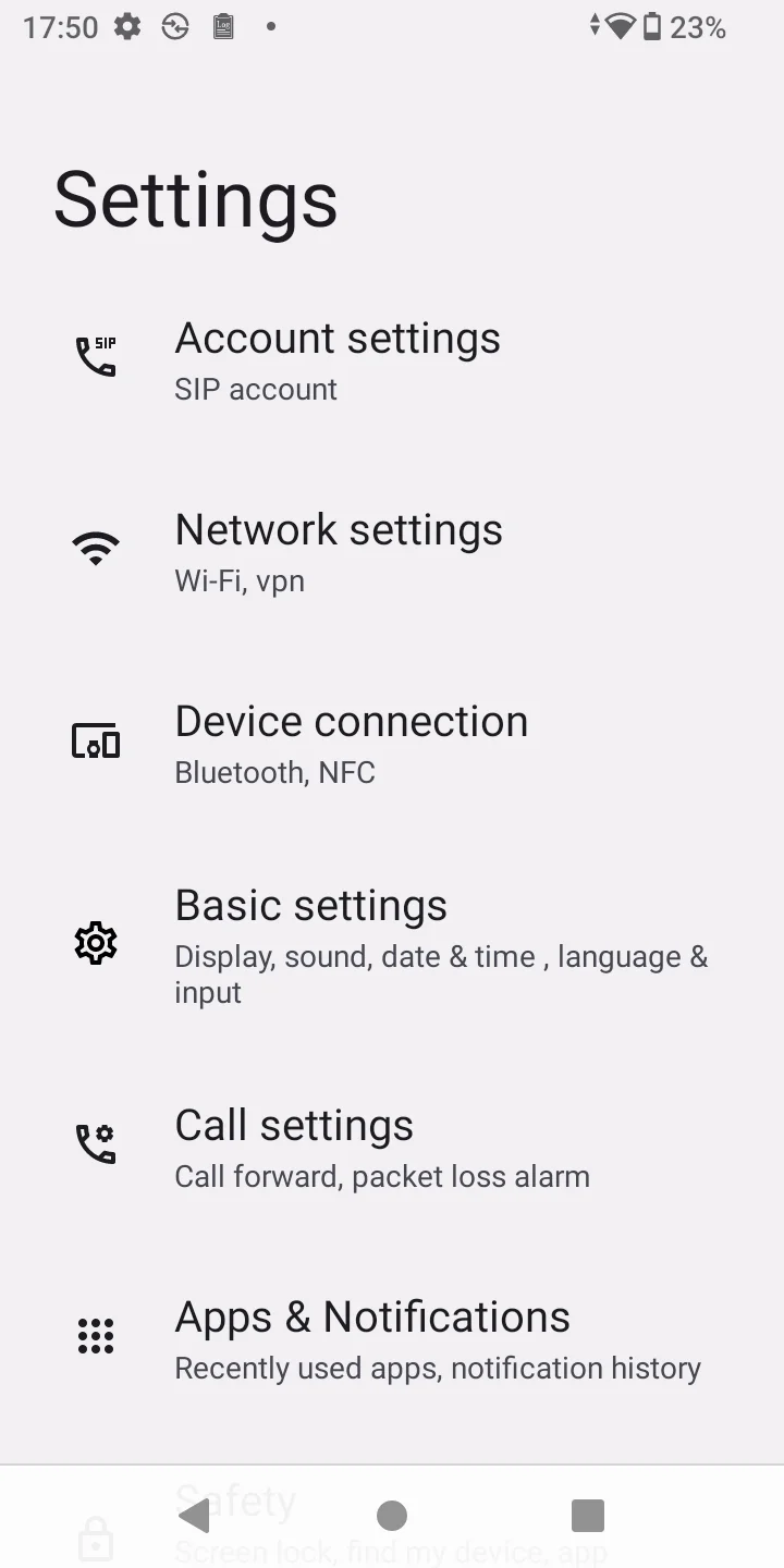
On the WP856 touchscreen menu, press the Menu key and navigate to GS Settings → Network Settings → Internet.
Set Wi-Fi to “On“. A list of Wi-Fi networks will be displayed.
Select the desired network to connect to. (Enter the correct password to connect if requested.)
WP856 will display the Wi-Fi icon on the main LCD menu if the connection to the Wi-Fi network is successful.
Wi-Fi Batch Deployment
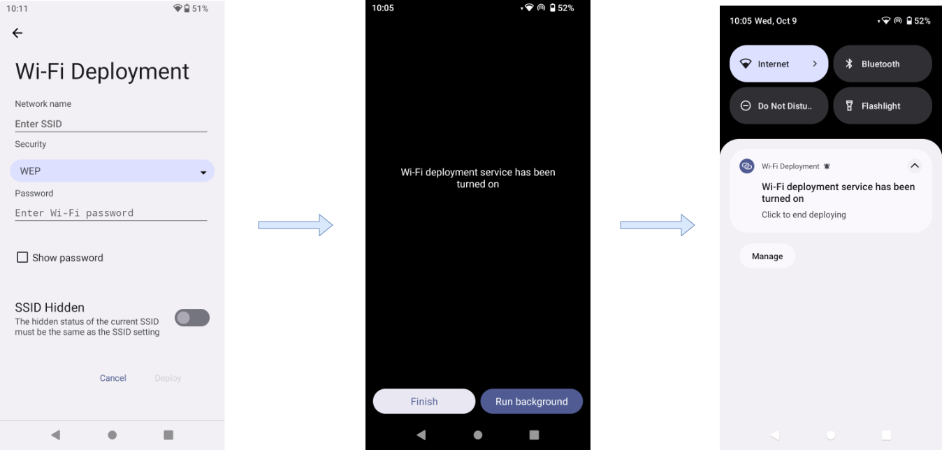
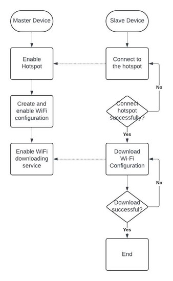
In some scenarios, WP856 can be set as a master device to deploy other units to the Wi-Fi network. This works as follows:
Enter the key code ( ***800* ) on the dial pad to enter the host mode, in which the device hotspot will be automatically turned on.
The Master device needs to fill in the Wi-Fi information ( SSID, security, password ), and then start the deployment.
The Master device will indicate that the Wi-Fi deployment service is enabled and can be used by other devices.
The Slave devices can connect to the SSID defined on the Master device and connect to the network by dialing the key code ( ***801* ) to enter the slave mode, and they automatically find the hotspot of the master device and establish a connection. Then download the Wi-Fi configuration parameter file, and automatically exit the slave mode after completing the Wi-Fi configuration.
Wi Fi Batch Deployment
The following flowchart explains the connection process:
Wi Fi Batch Deployment Flowchart
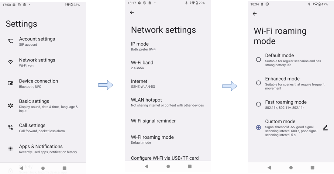
Wi-Fi Roaming Mode
Wi-Fi roaming allows the WP856 to seamlessly switch between different Wi-Fi access points within the same network. This ensures continuous connectivity without dropping the connection. This is typically used in environments with multiple access points, like large buildings or campuses,
To enable Wi-Fi Roaming, please follow the steps below:
Default mode: suitable for common scenarios, with strong battery life.
Enhanced mode: suitable for scenarios where you move around frequently.
Fast roaming mode: supports 802.11k, 802.11v, 802.11r;
Custom mode: You need to manually configure ‘Signal threshold’, ‘Roaming gain value’, Good signal scanning interval’, and ‘Poor signal scanning interval’
Select the preferred mode
Enable Wi Fi Roaming LCD
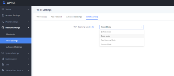
From the WebUI settings
Go to Network Settings → Wi-Fi Settings → Wi-Fi Roaming
Select the desired mode and click save
Enable Wi Fi Roaming WebUI
Wi-Fi Display
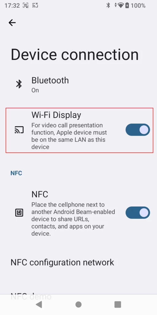
This feature allows the user to cast their screen to a display device through Wi-Fi to share a presentation. The IP phone can connect to the Wi-Fi network of the display device to start mirroring the screen of the IP phone.
The Wi-Fi display feature is disabled by default. To enable it, navigate on the device’s LCD screen to GS Settings → Device Connection,then enable Wi-Fi Display.
Enable Wi Fi Display
Connect to Bluetooth
The WP856 supports Bluetooth pairing, which can be used to pair wireless headphones, as well as other Bluetooth-enabled gadgets. To connect the WP856 to Bluetooth, please follow the steps below,
Go to GS Settings → Device Connection
Click “Pair a new device”
Search for nearby Bluetooth-enabled devices
Once the desired device is detected, pair it with the WP856 unit.
NFC device Connection
NFC (Near Field Communication) technology allows devices to communicate with each other wirelessly when they are in proximity, typically within a few centimeters. It operates at a frequency of 13.56 MHz and can transfer data at speeds up to 424 kbps. This technology can be enabled and used by the WP856 device. To connect WP856 using NFC, please follow the steps below:
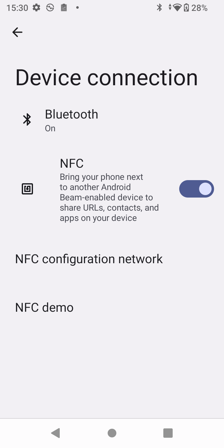
Go to GS Settings → Device Connection.
Enable NFC. Once enabled, bring the WP856 next to another Android Beam-enabled device to share URLs, contacts, and apps on your device.
Enable NFC
NFC Network Sharing
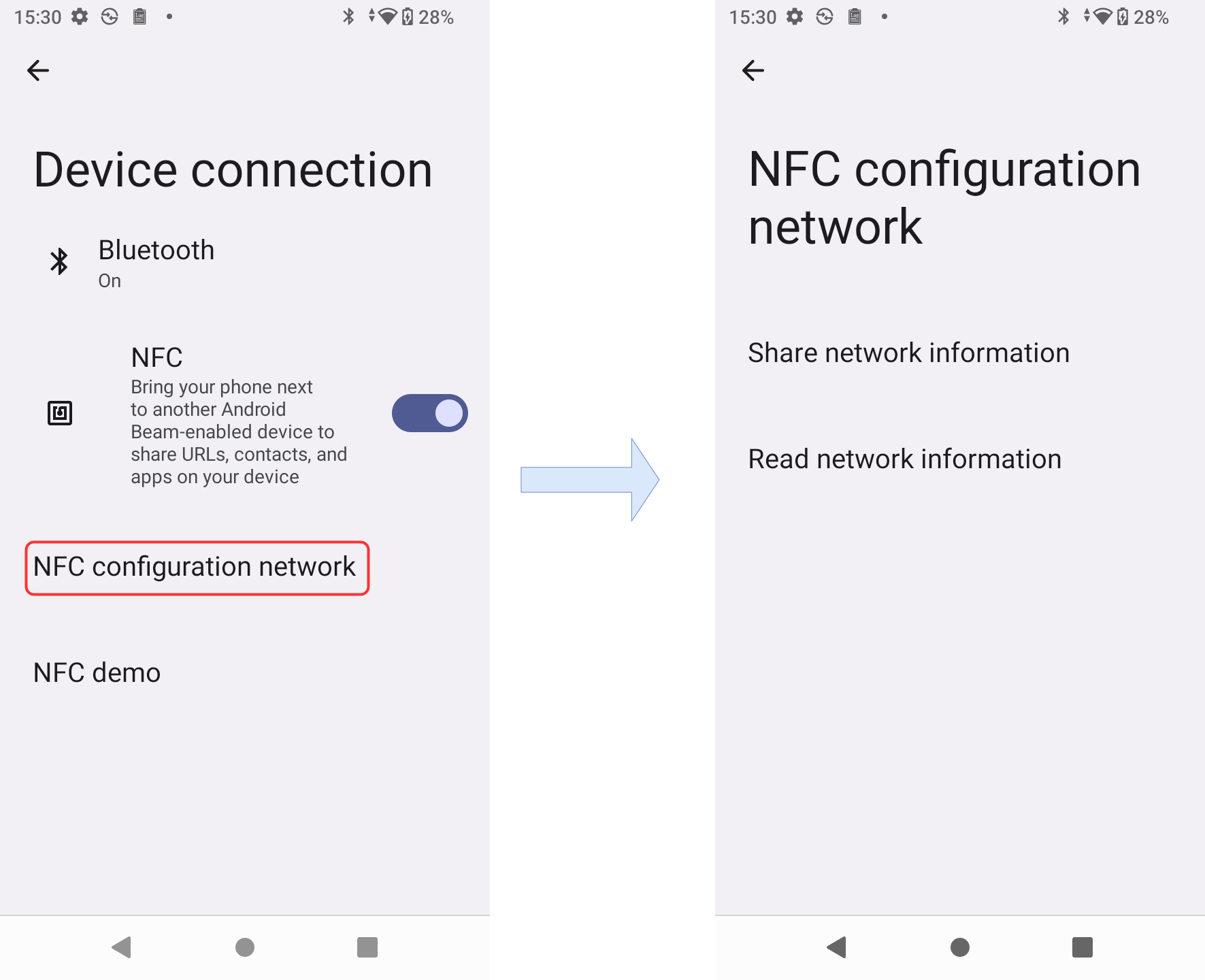
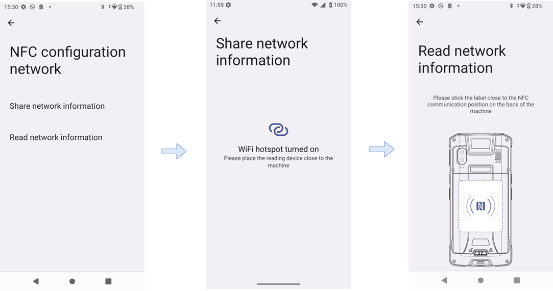
Users can share and read the network information of the WP856 via NFC. To do that:
Click on NFC configuration network, then Select Share Network information with the nearby connected device
You can also choose to read the network information before sharing it
NFC Network sharing
NFC to configure the Network
Note
If the wireless hotspot supports the hotspot sharing function, the mobile network can be converted into a wireless hotspot. The hotspot name and password can be transmitted to the device via the NFC chip. After the receiving device obtains the connection information through NFC, it can navigate to the WiFi connection page and connect to the hotspot network.
At the same time, the phone’s NFC supports reading WiFi NFC sensing tags. For example, the phone’s NFC function can read the NFC tag on a router. The tag contains the router’s wireless SSID name, password, and automatic connection instructions. When you touch the tag with WP856, it will automatically navigate to the WiFi connection page using the provided SSID and password and connect to the WiFi.
NFC Demo
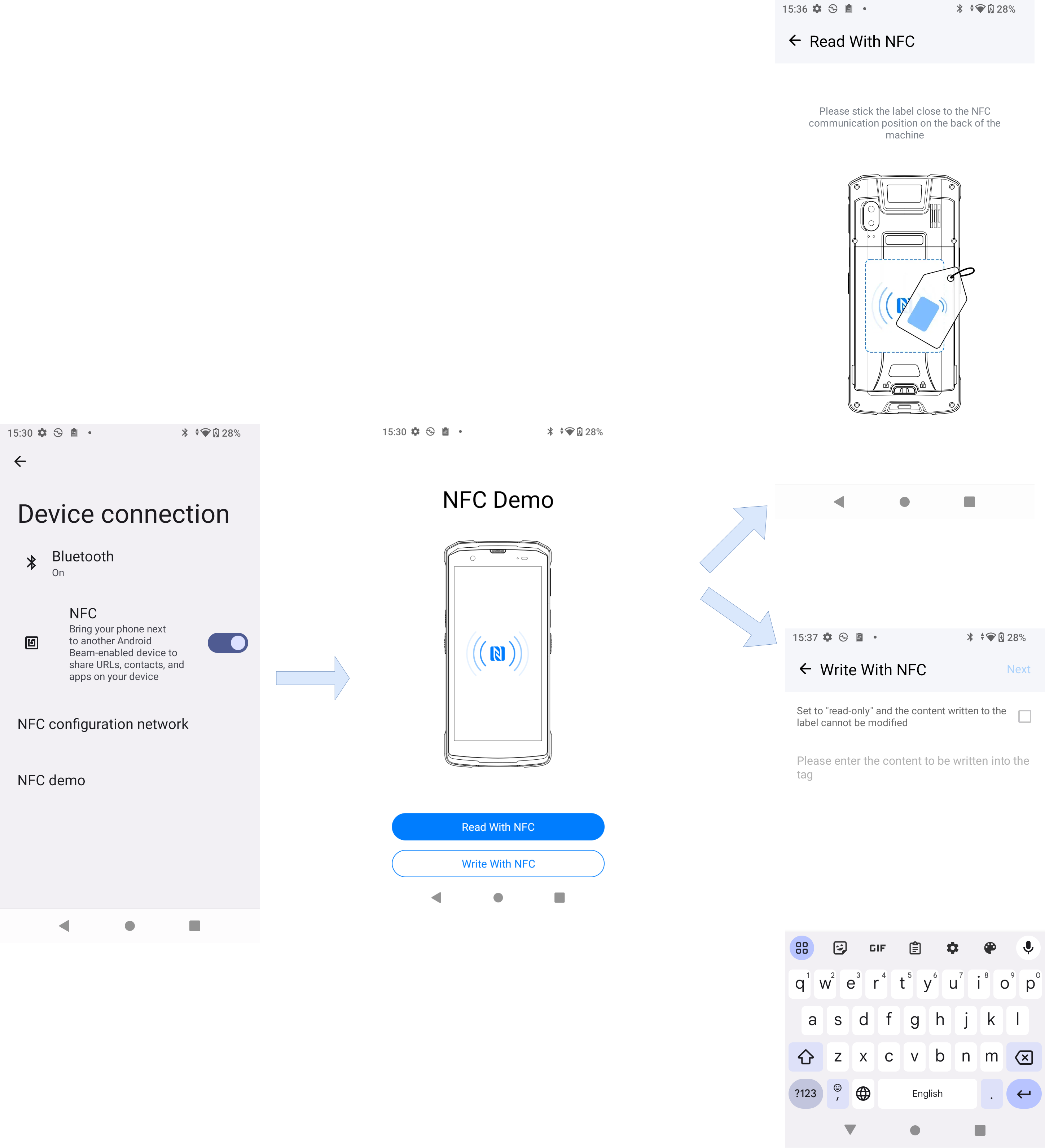
The WP856 presents an NFC demo to demonstrate to users how technology can be used to send and receive data:
Go to GS Settings → Device Connection
Click on the NFC demo
You can choose to receive data (Read with NFC) or send data (Write with NFC)
Read NFC tags: To use the NFC feature on your device, position the induction tag near the NFC communication area located on the back of the device. Once the tag is read, the content will be displayed within the app. A successful reading will be indicated by a sound and vibration prompt.
Writing to NFC tags: To edit the tag content, begin by writing the desired text information and deciding whether to set the sensor tag to “read-only” (which prevents further modifications to the tag’s content). Once ready, click Next. Then, place the NFC tag near the back of the phone to start the writing process. If the tag is not detected, the process will remain on this page. When the tag is detected, a beep will sound, and writing will begin automatically. The app will then indicate whether the writing process was successful or if it failed, based on the verification result.
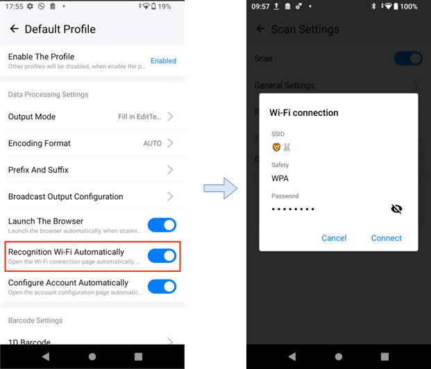
When [WiFi Identification] is enabled, scanning a QR code will automatically recognize it as a WiFi QR code. A pop-up window will display the WiFi SSID, password, and encryption method. Upon confirmation, the phone will connect to the Wi-Fi network.
Scan the QR code to configure the network
Check WP856 Device Info
To verify the WP856 device info, please follow the steps below:
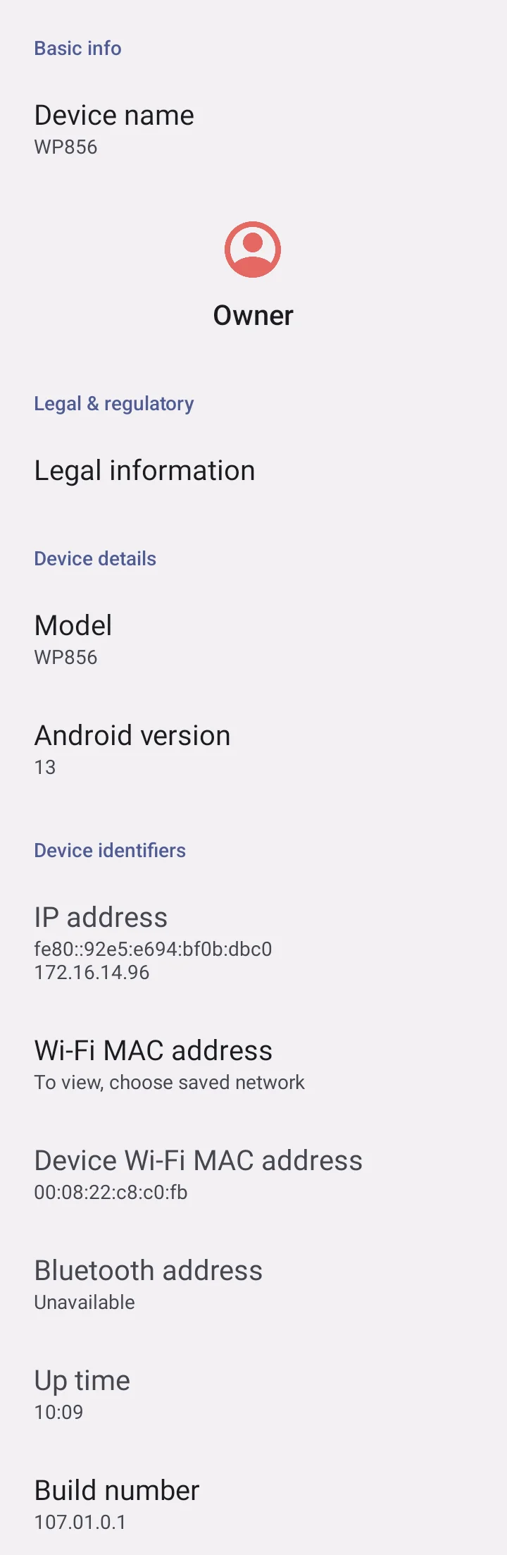
Go to GS Settings → About phone, this will allow the users to view various device information, such as Basic info, Legal and regulatory information, Device details, and device identifiers
WP856 Device Info
Check WP856 Account Status
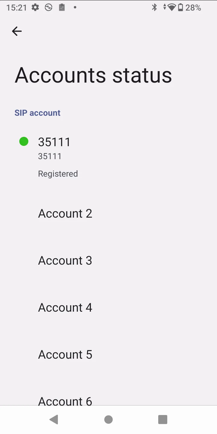
The WP856 supports configuring up to 6 SIP accounts. When configured, you can view their status under GS Settings → About Phone → Account Status.
WP856 Account Status
Checking WP856 System information
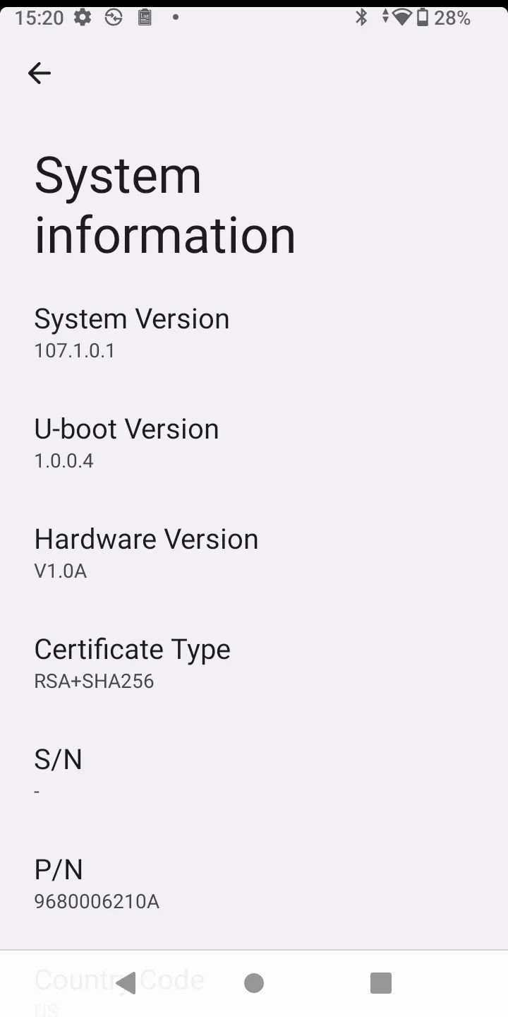
WP856 system information can be viewed under GS Settings → About phone → System information. This page will display the following information:
WP856 System Information
WP856 INTELLIGENT ASSISTANCE
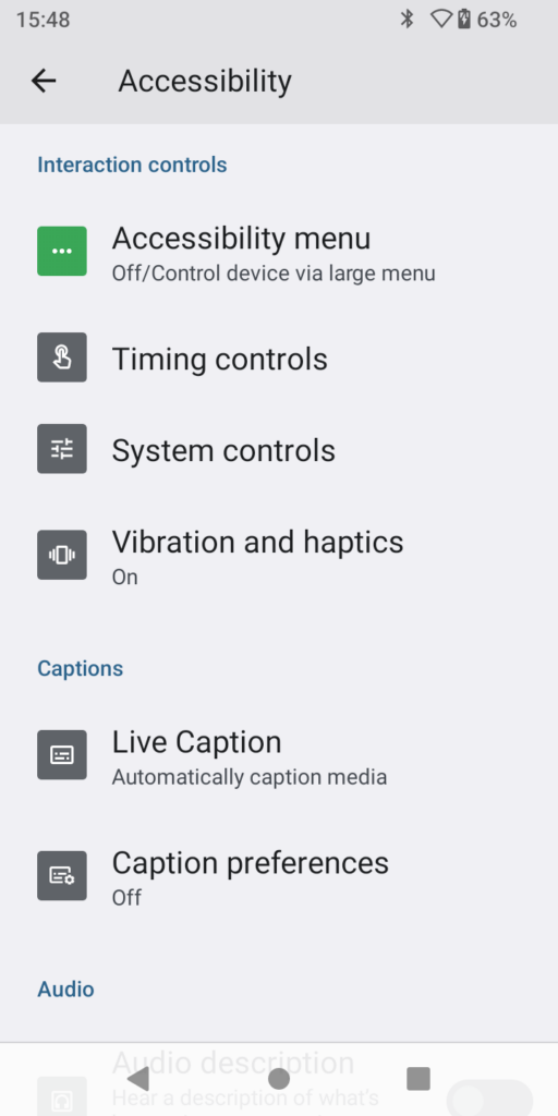
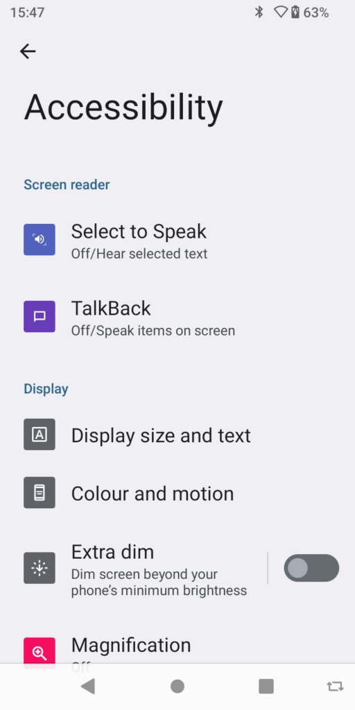
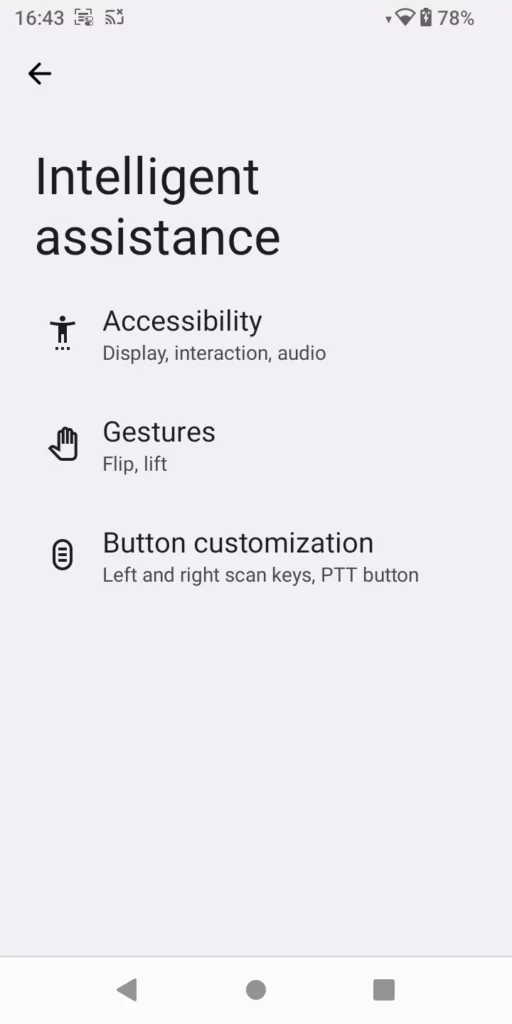
The WP856 mobile computing device presents a list of accessibility and gesture features to enhance the user experience. This will allow users to customize their device on a granular level to suit their day-to-day deployments need. Among the settings, we have: accessibility settings, Gesture settings, and Button customization.
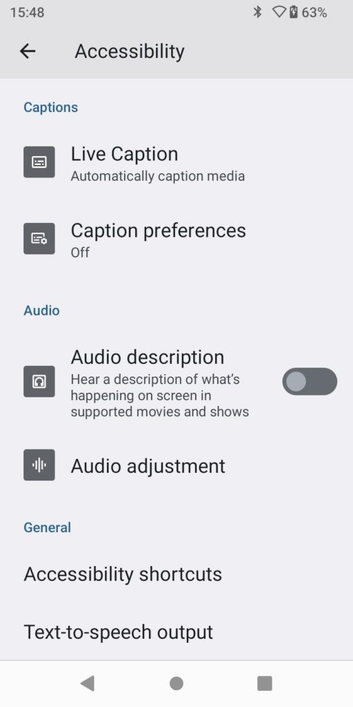
WP856 Accessibility Settings
The WP856 presents a list of accessibility settings. We can describe each one of them below:
The accessibility settings can be accessed under GS Settings → Intelligence assistance.
Screen Reader:
Select to Speak: Reads aloud selected text on the screen to assist users with visual impairments.
TalkBack: Provides spoken feedback and screen reader functionality for navigating the device without looking at the screen.
Display:
Display size and text: Adjust the size of text and display elements to improve readability.
Color and motion: Modifies color settings and reduces motion effects to aid users with visual sensitivities.
Extra dim: Lowers screen brightness beyond the minimum setting for comfortable viewing in dark environments.
Magnification: Allows users to zoom in on parts of the screen for better visibility.
Interaction Controls:
Accessibility menu: Provides a simplified menu with large buttons for easier access to common functions.
Timing controls: Adjusts the duration of screen and interaction timeouts to accommodate different user needs.
System controls: Provides access to various system settings for ease of navigation and customization.
Vibrations & haptics: Adjusts vibration patterns and haptic feedback for notifications and interactions.
Captions:
Live Caption: It detects speech on your device and automatically generates captions. Note that this feature increases the battery consumption.
Caption Preferences: In this option you can customize the captions by adjusting the size and the style of the text, as well as selecting the default language.
Audio:
Audio description: Enables spoken descriptions of visual content in media for users with visual impairments.
Audio adjustment: Customizes audio settings, such as balance and volume levels, for a personalized listening experience.
Accessibility Features 1
Accessibility Features 2
Accessibility Features 3
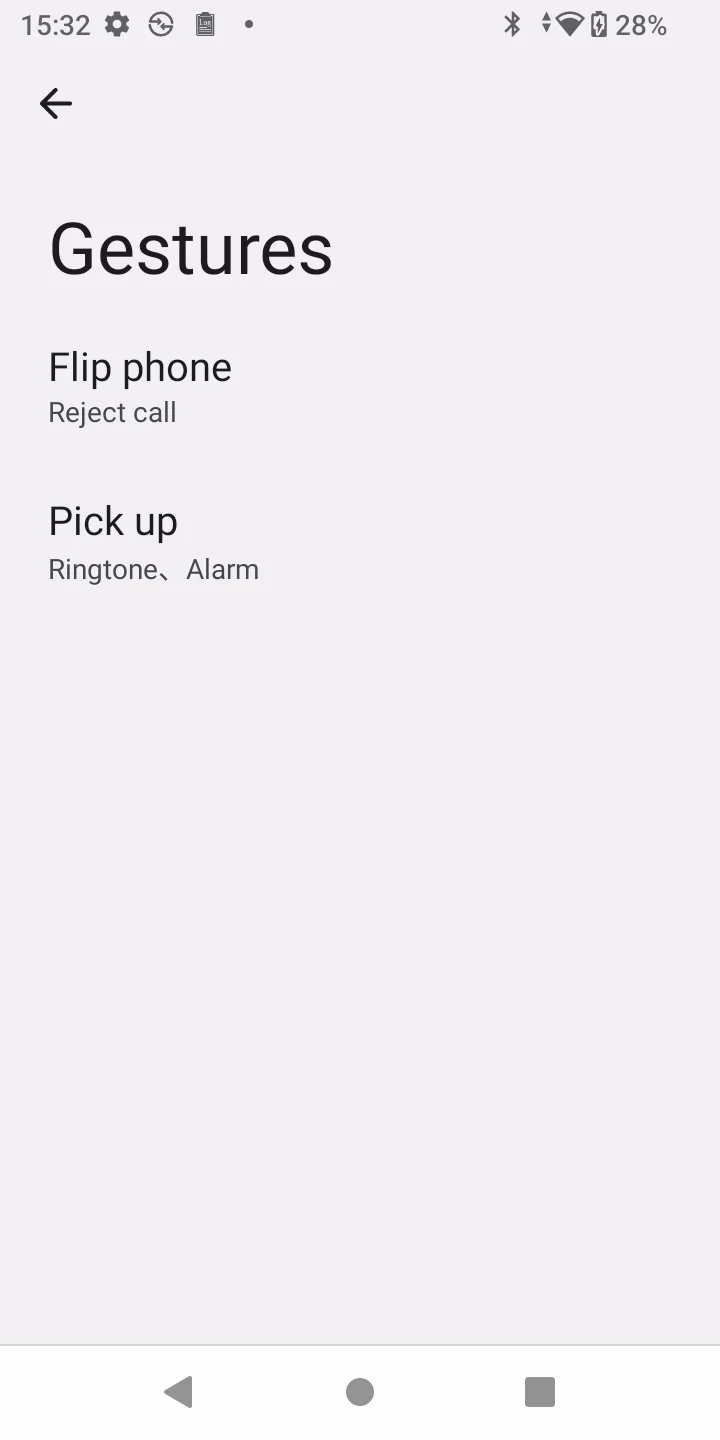
WP856 Gesture Settings
Gesture settings allow users to control their WP856 device using specific hand movements, such as swiping, tapping, or pinching, enhancing accessibility and providing an alternative to traditional button-based navigation. These settings can be customized to perform various actions,
The gestures supported on WP856 are :
Flip phone: This will define the reaction of the phone when being flipped during an incoming call; it can be set to reject the call or to silence it
Pick up: Lifts the phone to your ear to automatically answer calls or activate specific functions like waking the screen.
Gestures Settings
The gesture settings can be accessed under GS Settings > Intelligence assistance.
WP856 Button Customization
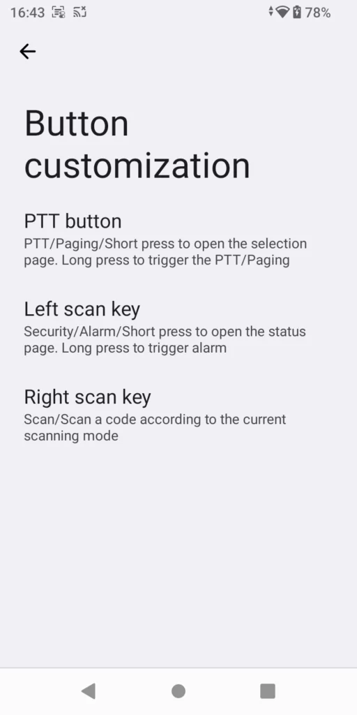
The Button Customization settings can be accessed under GS Settings > Intelligence assistance.
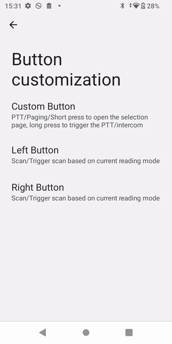
The WP856 supports three customizable hard key buttons on the side of the device:
Intelligent Assistant Configuration
Intelligent Assistant Button Customization
PTT button: can be configured for PTT/Paging, short press to open the selection page, long press to trigger the PTT/intercom
Left Scan Key: Security/Alarm/Short press to open the status page. Long press to trigger alarm.
Right Scan Key: Scan/Scan a code according to the current scanning mode.
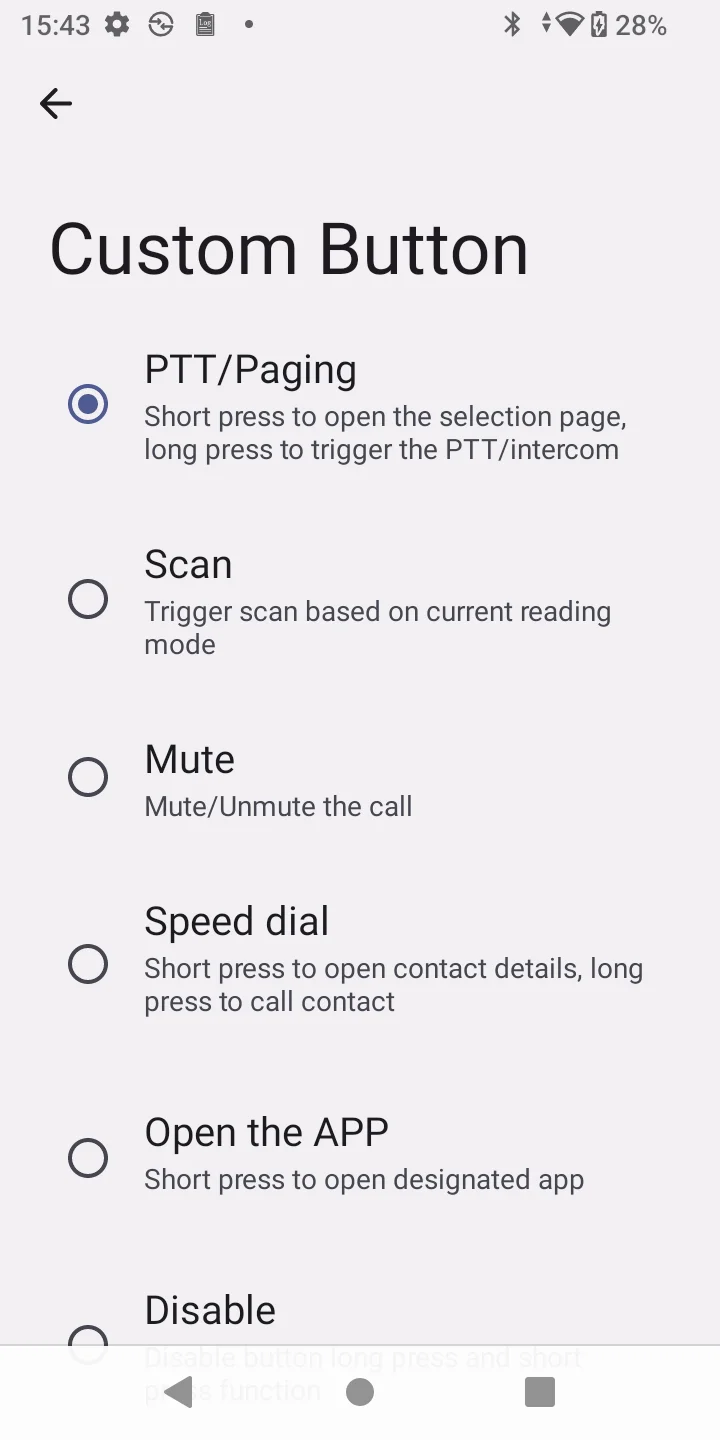
Custom button settings
PTT/Paging: Short press to open the selection page, long press to trigger the PTT/intercom.
Scan: Trigger scan based on current reading mode.
Mute: Mute/Unmute the call.
Speed dial: Short press to open contact details, long press to call contact.
Open the app: Short press to open designated app.
Custom: Long press to send an intent action handled
Zoom PTT: Press to open Zoom app. Press and hold to trigger Zoom push to talk (Zoom app required).
Simulate Keyboard key: Short press to output the designated key event, users can select one of the following keys to be sent: Enter, Tab, or Space, users can select the Custom Keyboard key, and the input range is 1-95, except the value 26 .
None: short press or long press do not trigger any function.
Left Right Button
Left button: Scan/Trigger scan based on the current reading mode using the left button
Right button: Scan/Trigger scan based on the current reading mode using the right button
WP856 ADVANCED SETTINGS
The WP856 mobile computing device offers customizable configurations for various parameters on the LCD, including the following:
Push-to-Talk settings on the WP856 enable instant voice communication by pressing the configured custom button for PTT, while Group Paging settings facilitate broadcasting messages to a predefined group of users. Both methods can be implemented as shown below,
To configure Push-to-talk or Group Paging on the WP856 LCD:
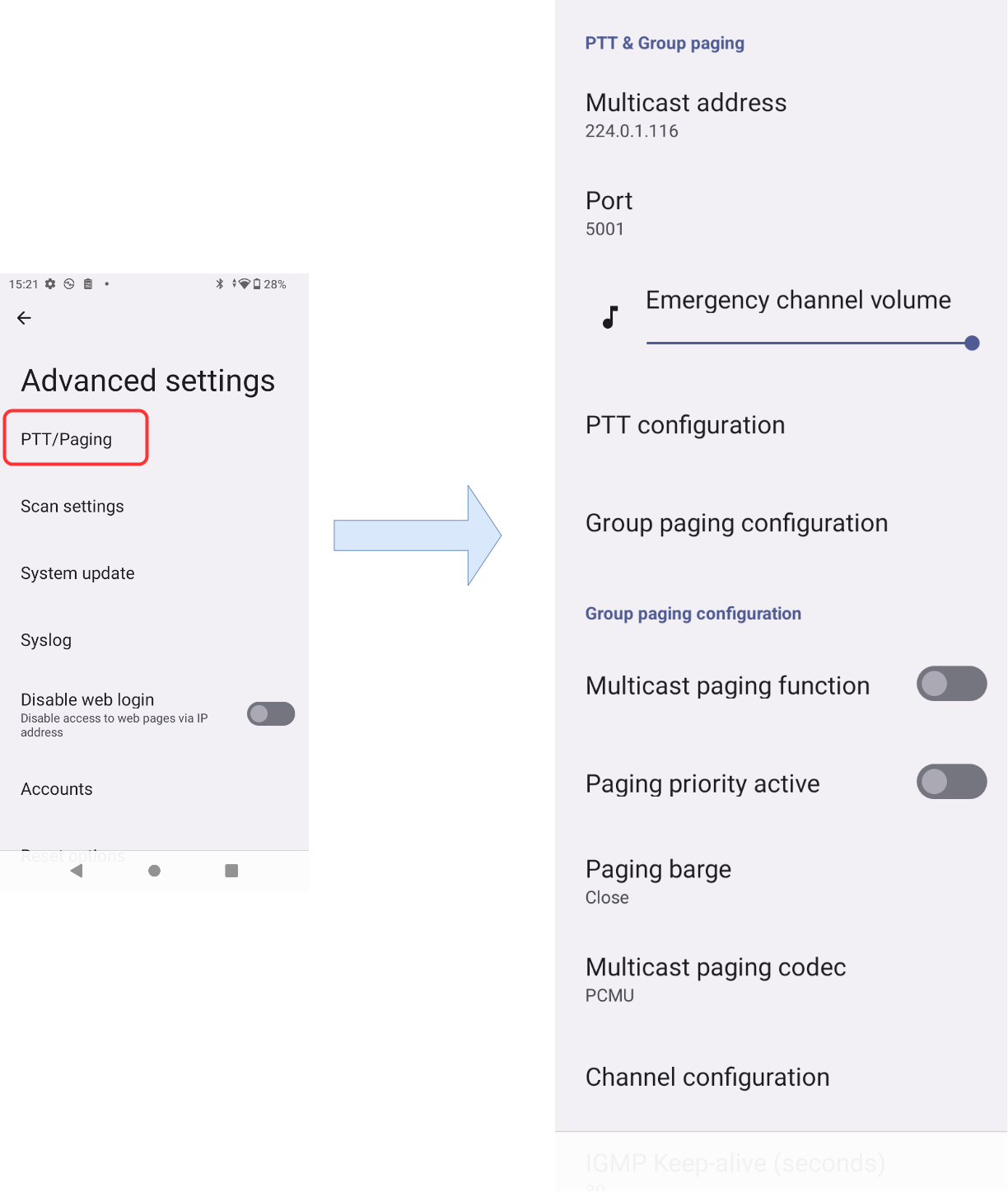
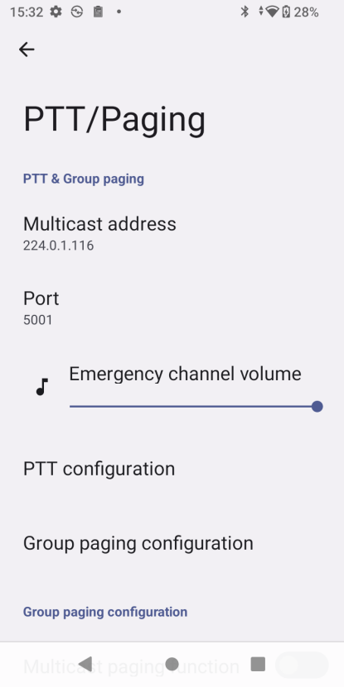
Access GS Settings → Advanced Settings→PTT/Paging, or short-press the configured customizable button when configured for PTT/Paging. Please check [WP856 Button Customization] for more information on how to set it up
Under PTT & Group paging, define the multicast address that will be shared between the receivers
Define the RTP port that will be used
On the PTT configuration, you can define the default channel, priority channel, and emergency channel.
PTT Group Paging Settings
Some additional Group paging configurations can be defined here
Multicast Paging Function: Allows multiple devices to receive a page simultaneously via multicast transmission
Paging Priority Active: Determines the priority level for paging, ensuring higher priority pages override lower ones
Paging Barge: Permits interruption of an ongoing lower-priority page by a higher-priority one.
Multicast Paging Codec: Specifies the audio codec used for compressing and decompressing the multicast page audio
Channel Configuration: Defines the settings and parameters for each communication channel in a system
Once configured, press and hold the customizable button when configured on PTT, and the paging communication will take place.
For paging channel configuration, the user can navigate to Phone Settings → PTT/Paging.
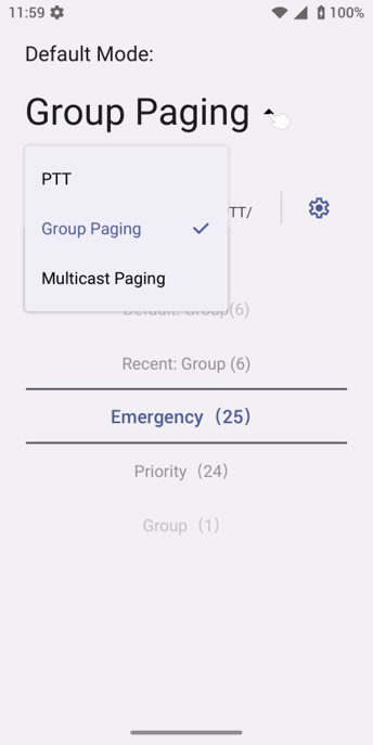
The paging supports 50 channels, divided into two groups: PTT (1-25) and Paging (26-50). Each group of channels is divided into three types according to priority: Normal, Priority, and Emergency.
To send a PTT, press and hold the PTT button, and the channel status will change to Send PTT to indicate that a conversation is in progress. Devices in the same channel will receive the PTT call. After the conversation is completed, release the PTT button. The channel will be released in 10 seconds.
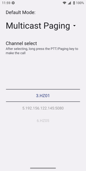
To send a paging: after setting the “Default Mode” to multicast, select the channel to send multicast in the channel selection area, press and hold the PTT/Paging button to enter the multicast sending interface, and start speaking. All devices set to the same group can receive the multicast paging.
Both support the “Auto answer while busy” function. When the user is on a call or intercom, if there is a PTT/multicast call of the same level, it will be automatically answered.
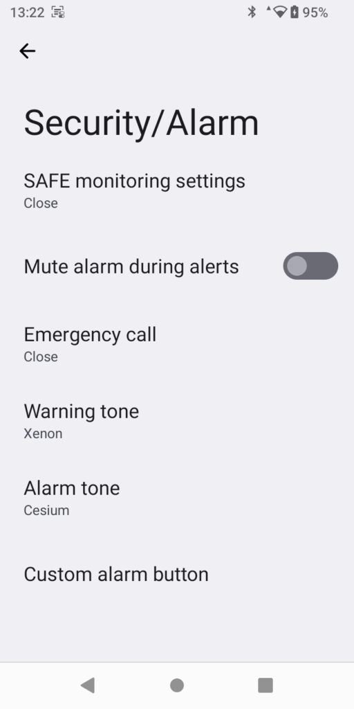
Security/Alarm
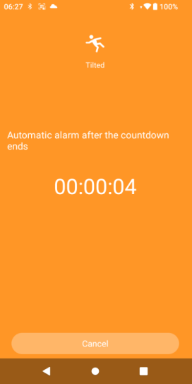
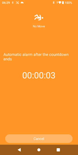
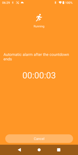
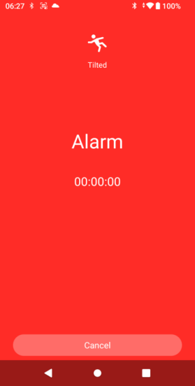
Security and alarm feature takes advantage of the different sensors in the phone to monitor the safety of the user, e.g., a significant and sudden tilt will trigger an alert, if the user does not cancel the alert to indicate that they are safe, an alarm will be played at maximum volume to draw the attention of the staff around to the user. This measure ensures that, in case a slip and fall occurs to a staff member, immediate medical care can be provided to the staff member as soon as possible.
SecurityAlarm
Below are examples of the alerts triggered for different events.
Below is an example of a triggered alarm.
SAFE Monitoring Settings
Parameter
Description
Security Monitoring
Switch the toggle to enable/disable the security monitoring features.
Note: By default, this setting is disabled.
No Movement Sensitivity
Enables no movement detection security measure. When the user remains for a period longer than the timeout, the phone will send an alert. If the user does not cancel the alert, an alarm will be played by the phone.
Select the sensitivity levels. There are 7 levels of sensitivity.
If you set a high sensisitivity level, the phone movement sensor will detect even the slightest of movement and vice versa.
The timeout indicates the configure time before an alarm is triggered after receiving the alert.
Tilt Sensitivity
Enables tilt detection security measure. When a significant tilt is detected, the phone will alert the user. The user can cancel the alert to indicate that they are safe before timeout, if not, the alarm will be played.
If the tilt sensitivity is set to a high level, the phone will detect the slight tilt movements.
Running Sensitivity
Enables running detection security measure. When running is detected, the phone will send an alert and the user cancels the alert, the phone will continue monitoring running movement. If running is still detected, the phone will send an alert again after the snooze timeout. Running timeout indicates that minimum time of running movement before triggering the alert.
Mute Alarm During Alerts
Enabling this option mutes any alarms that were triggered before an alert.
Emergency Calls
Parameter
Description
Emergency Call
Enable/disable emergency calling.
Note: This options is disabled by default.
Hands Free Mode
Enable/Disable handsfree mode.
Note: This option is disabled by default.
Local Account User for Calling for Help
Enter the number to call for urgent help.
Warning Tone
Select the tone to play when an alert/warning is triggered.
Alarm Tone
Select the tone to play when an alarm is triggered.
Custom Alarm Button
Select the button to use to trigger an alarm manually.
Physical Button
Function Mapping
PTT Button
Left Scan Key
Right Scan Key
Select the function mapping of the physical button.
PTT/Paging: Short press to open the selection page. Long press to trigger the PTT/Paging.
Scan: Scan a code according to the current scanning mode.
Security/Alarm: Short press to open the status page. Long press to trigger an alarm.
Mute: Mute/Unmute the call.
SpeedDial: Short press to open contact details. Long Press to call the contact
Opentheapp: Short press to open the designated app.
Custom: Long press to send an intent action handled by a specific app.
ZoomPTT: Press to open Zoom app. Press and hold to trigger Zoom PTT (Zoom application required).
SimulateKeyboardKey: Short press to output the designated key event
Disable: Disable the button’s long-press and short-press functions.
Monitor Settings
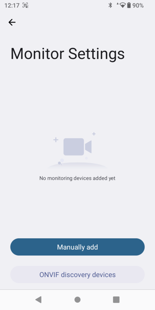
In Monitor Settings, the user can add ONVIF cameras for monitoring. To access Monitor Settings, on the LCD, access GS Settings → Advanced Settings → Monitor Settings.
Monitor Settings
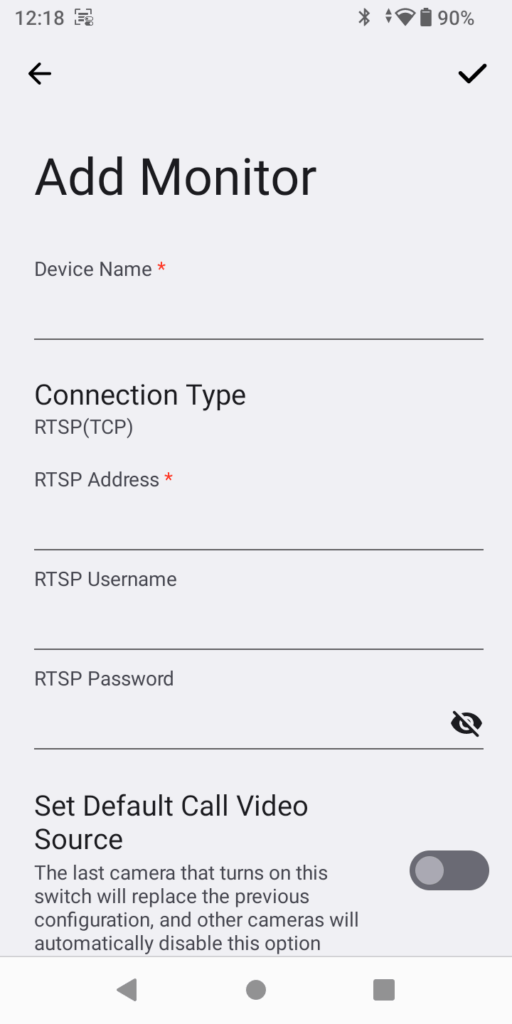
Tapping on Manually add prompts the user to configure the parameters of the monitoring camera.
Add Monitor
Device Name
Enter the device’s name.
Connection Type
RTSP(TCP)
RTSP(UDP)
RTSP(Multicast)
RTSP Address
Enter the IP address of the monitoring camera. In case the Connection selected is RTSP(Multicast), enter a multicast address which is configured on the monitoring device.
RTSP Username
Enter the username.
RTSP Password
Enter the password.
Set Default Call Video Source
The last camera that turns on this switch will replace the previous configuration, and other cameras will automatically disable this option.
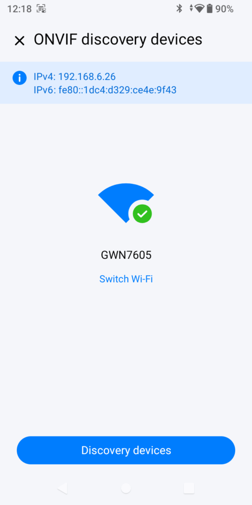
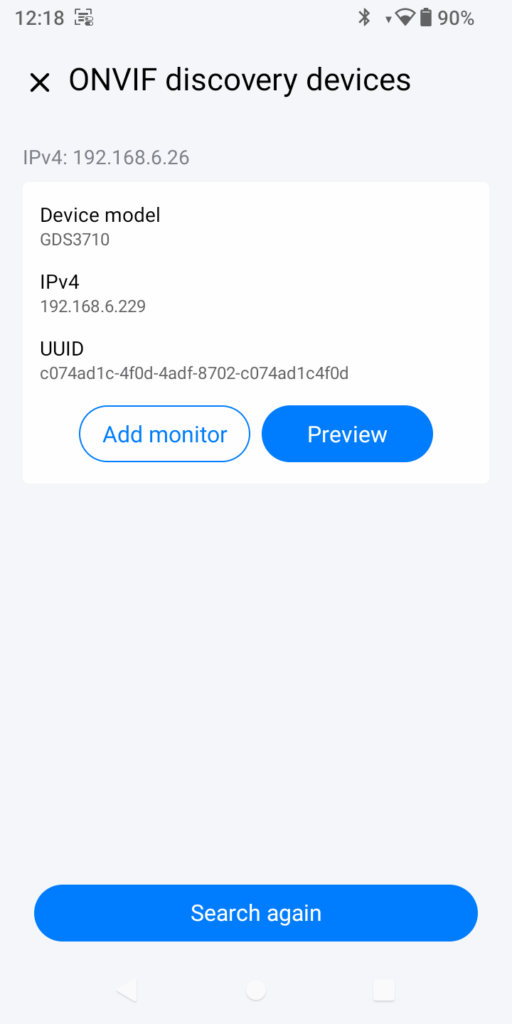
If ONVIF Discovery Devices is selected, the phone will scan the network to detect the monitoring devices.
ONVIF Discovery Devices
Once a monitoring device is found, the user can preview the video feed of the device before adding it, or they can directly add it to the list of devices for quick access. Adding the device or previewing the video feed requires entering the admin username and the password.
Monitoring Device Found
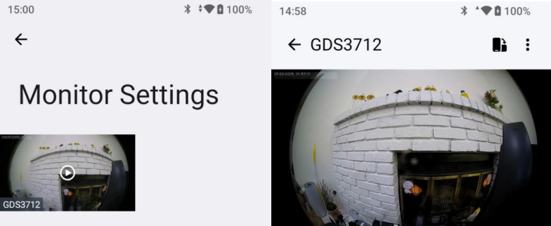
When the device is added, the user can access the camera feed as demonstrated in the screenshot below.
Scanning Settings
The WP856 features an essential barcode scanning capability that allows users to scan 1D and 2D barcodes and synchronized to database using methods like Bluetooth, USB, or sent to a server over the network, etc. It uses an integrated light scanner which can be activated through the Scan Demo app and triggered by pressing the left or right scan buttons.
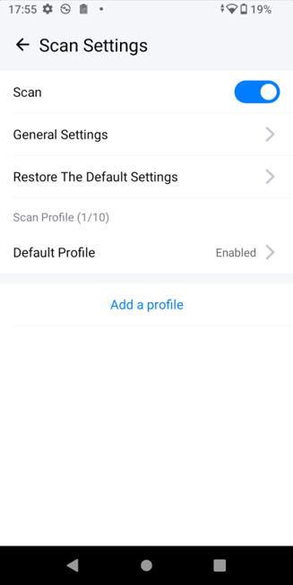
Scan Settings can define the scan profile used to scan 1D and 2D barcodes. The configuration on the WP856 is as shown below:
Access app launcher and tap “Scan Settings”
Enable Scan option
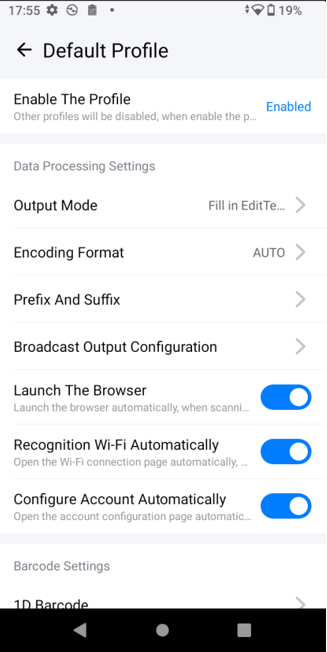
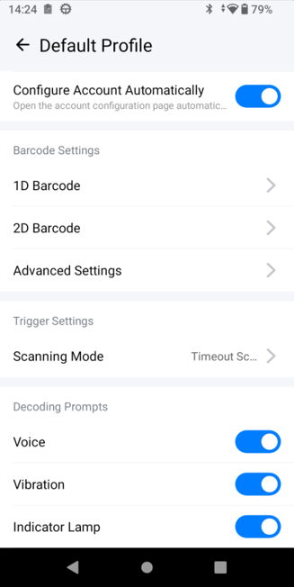
Edit the Default profile after being enabled, and the following settings can be defined:
Output Mode: Specifies how scanned data is processed and delivered, whether as keyboard input or file output. Output modes include emulating key input, directly filling in text fields, broadcasting data, USB HID output, Bluetooth HID output, and network output.
Encoding Format: Specifies the character encoding used for the scanned data.
Prefix and Suffix: Adds specified characters before (prefix) or after (suffix) the scanned data.
Broadcast Output Configuration: Configures how the scanned data is broadcast to applications.
Launch the Browser: Opens a web browser automatically after a scan.
Recognition Wi-Fi Automatically: Enables automatic connection to recognized Wi-Fi networks.
Configure Account Automatically: Sets up user accounts automatically upon scanning.
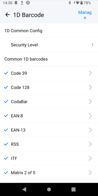
1D Barcode: Configurations specific to one-dimensional barcode scanning.
2D Barcode: Configurations specific to two-dimensional barcode scanning.
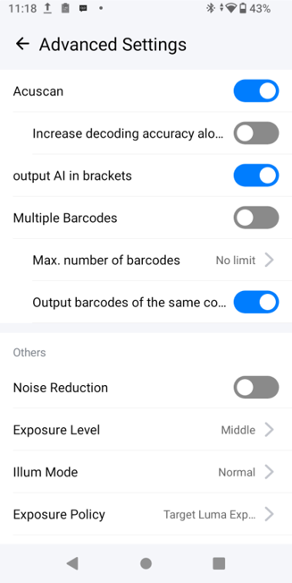
Advanced Settings: Provides access to additional, detailed configuration options.
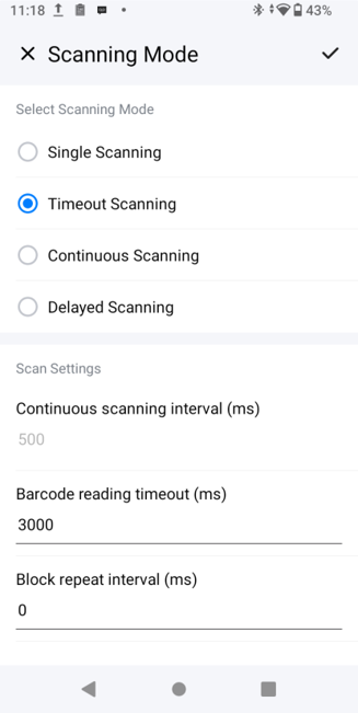
Scanning Mode: Select the operational mode of the scanner (e.g., continuous, single scan).
Decoding Mode (Voice, Vibration, and Indicator Lamp): Configures feedback methods (audio, vibration, and visual) after a successful scan.
For more detailed information on how to use the barcode scanning features on the WP856 device, please visit the guide: WP856 Code Scanning Guide
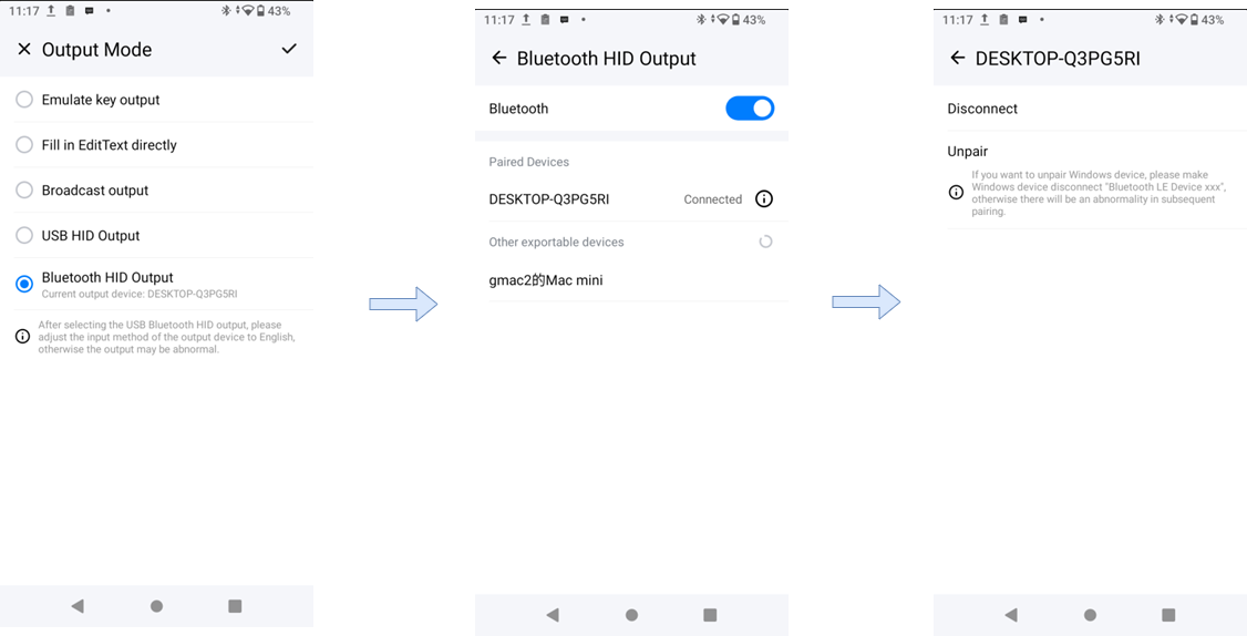
Bluetooth HID Output
To configure Bluetooth HID Output, please follow the steps below:
After selecting Bluetooth HID output, you need to select a pairable device in the output device list and connect it.
Click the device details in the paired device list to disconnect the device or cancel the pairing.
After selecting Bluetooth HID at the same time, the notification bar will display the current output mode and output device. Click to directly enter the output mode selection page.
When scanning code is abnormal:
Bluetooth HID output, Bluetooth is not turned on, but not connected to a Bluetooth device. After scanning the code, a toast prompt appears: ‘Bluetooth is not turned on, please turn on Bluetooth’, ‘Bluetooth device is not connected, please check Bluetooth settings’.
Bluetooth HID output: the Bluetooth device is connected. After scanning the code, it is judged as a Bluetooth device type that cannot be output. The toast prompts “The current Bluetooth device cannot be output. Please connect a Bluetooth device such as a mobile phone or computer.”
Bluetooth HID Output
Note
If you cancel pairing with a Windows device, you also need to disconnect “Bluetooth LE Device ec74d7229485 (Bluetooth MAC address)” on the device. Otherwise, subsequent pairing attempts may not function correctly.
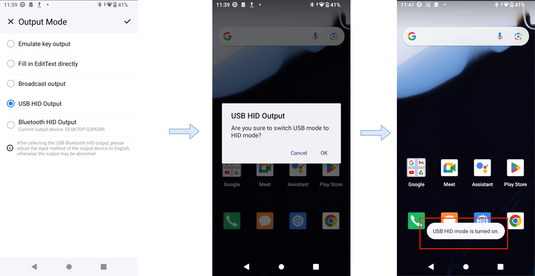
USB HID Output
To configure the USB HID Output, please follow the settings below:
Access the app launcher then tap Scan Settings → Profile → Output Mode
To use USB HID output, you need to connect the output device via a USB port.
After selecting USB HID output, each time you connect a USB, a prompt will pop up to ask to switch the USB mode to HID mode.
After unplugging the USB, it will automatically restore to the previous USB mode.
After selecting USB HID, the notification bar will display the current output mode. Click it to directly enter the output mode page.
USB HID Output
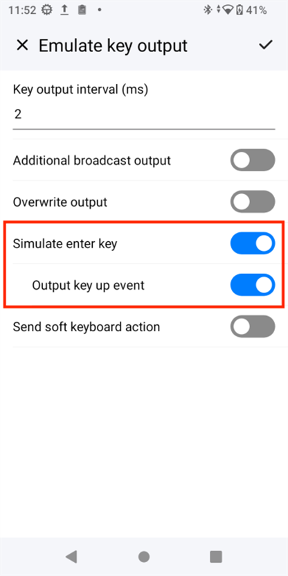
Simulate the Enter key
Access the app launcher then tap Scan settings → Profile → Output Mode
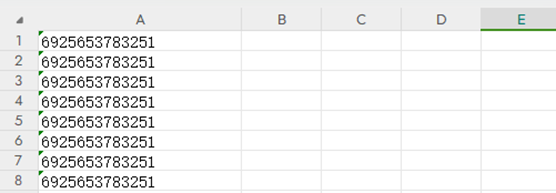
This function is effective for simulating key output, USB HID, or Bluetooth HID output. It is used to realize an automatic jump after scanning the code and pressing Enter. Please turn this function on or off according to actual needs.
Simulate the Enter key
Turn on the simulated enter key
Simulated Enter key is not enabled
CALLING OPERATIONS
In this section of the guide, we will demonstrate how we can configure telephony-based operations on the WP856.
Register SIP Account
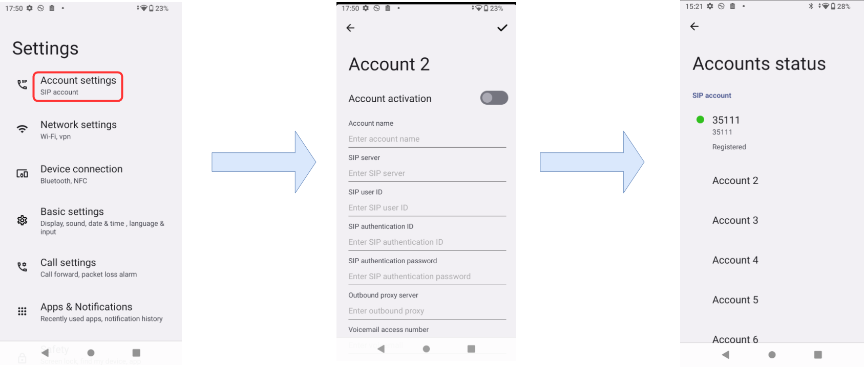
To register an SIP account from LCD Settings, please follow the steps below,
Under GS Settings → Account Settings → SIP Account, select the account to configure; it will be account 2 in our case.
Define the following fields:
SIP Server
SIP User ID
SIP Authentication ID
SIP Authentication Password
Outbound Proxy Server
Voicemail access password
Toggle Account Activation
Click Save. After the mentioned steps, the account will be registered
Register SIP Settings
Configure SIP Account through UCM QR Code
Users can scan QR codes to automatically configure the SIP accounts on the WP856 device. To do that, please follow the steps below:
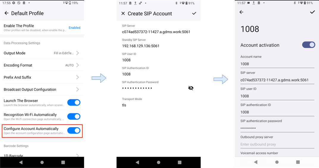
From LCD settings, Access Scan Settings → Profile → Configure Account Auto
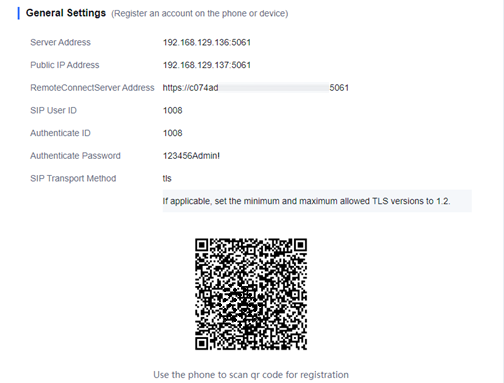
When the Configure account automatically is enabled, scan the QR code sent by UCM to automatically identify the SIP server address, backup SIP server address, SIP user ID, SIP authentication ID, and SIP authentication password.
Scan the QR code from UCM
Then WP856 will navigate to the settings page of an empty account, automatically fill in the recognized information, and complete the account configuration.
If all accounts have been configured, users can choose which account information to replace from the 6 accounts available.
LCD settings for automatically adding an SIP account
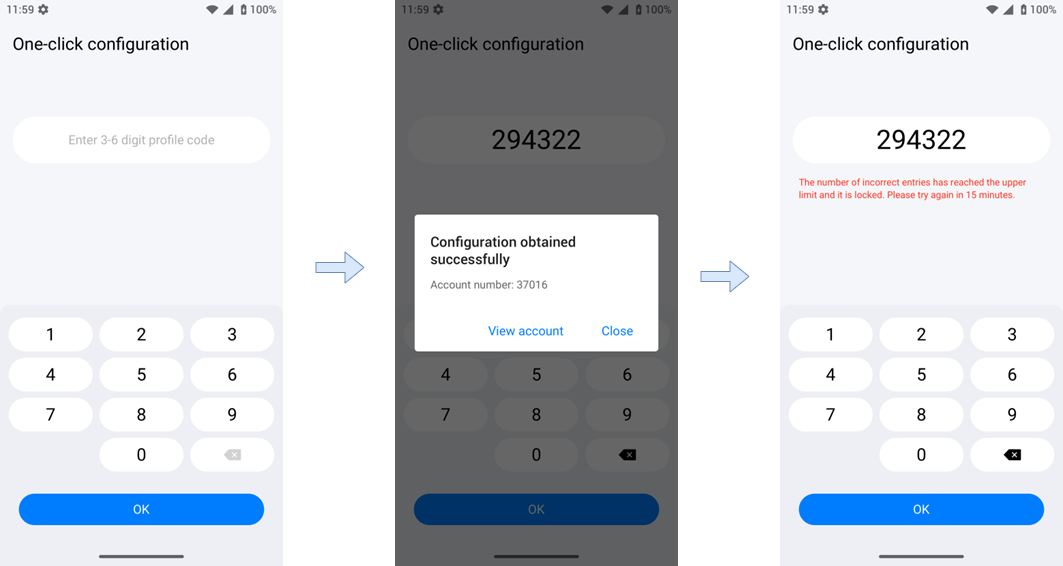
One-Click Configuration
The WP856 can have a SIP account deployed to it using the one-click configuration method. This is done by providing a 6-digit code generated by the GCC60xx convergence device to deploy the SIP account on the WP856 unit. The way it works is as follows:
A unique 6-digit identification code is automatically generated by the GCC60xx device.
Employees can quickly configure extension accounts and log in by entering their own identity codes on WP856. By default, the account is configured to “Account N” (the one with the smallest number N). If all accounts have been configured, the account is configured to replace the last account.
By default, if the user enters an incorrect or invalid ID code 5 times, the ID code will be locked. If it is locked, the user needs to try again after 15 minutes. (The specific number of times and lock time can be determined by GCC)
One Click Configuration
Incoming call
To answer an incoming call, press the icon on the LCD screen.
To reject an incoming call, press the icon on the LCD screen
When a call is received and is not answered, the user can use quick replies to send SMS messages to the caller. These responses are preconfigured and can be sent using one tap (e.g., I’m busy, I’ll call you later.)
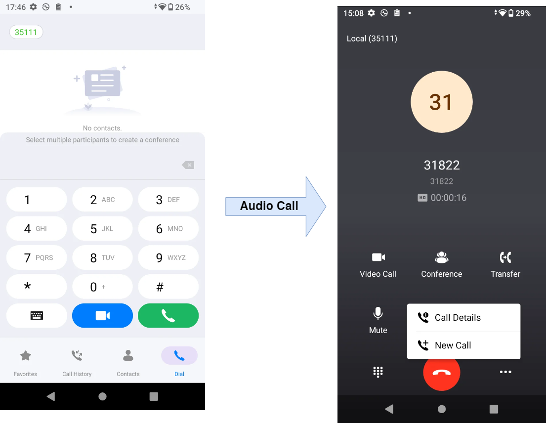
Outgoing call
To make an outgoing call:
Click the dial icon on the LCD screen
Enter the number you would like to call
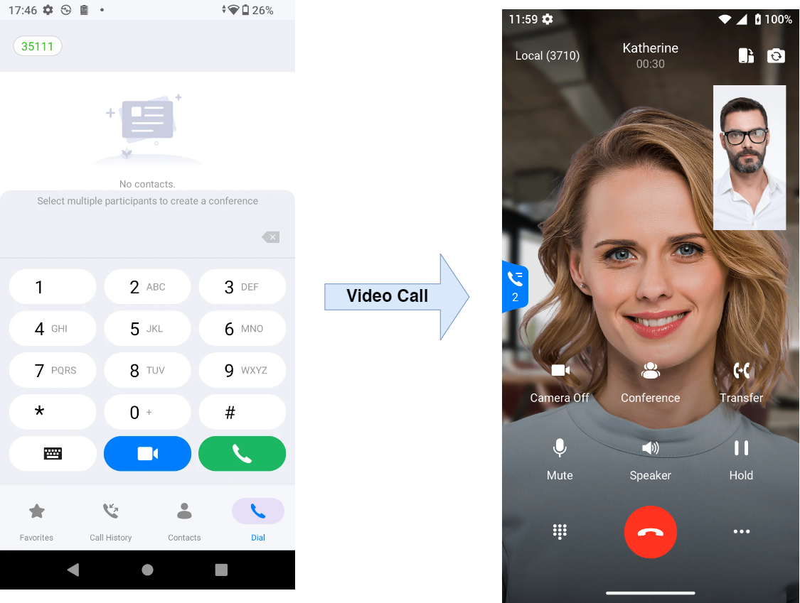
Press the icon to trigger an audio call, and the icon to trigger a video call
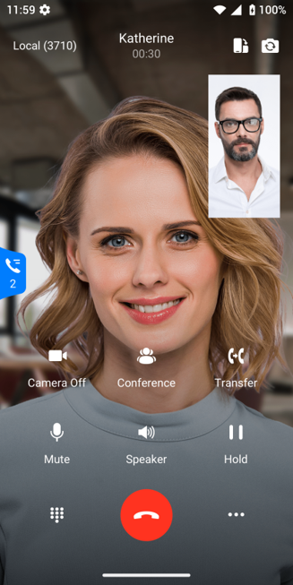
Once the call is connected, you will be able to hear/see the callee.
Audio Call
Video Call
: When tapping this icon, the user can choose the front or the back camera.
: When tapping this icon, the user can switch the display orientation of the phone from portrait to landscape, or vice versa.
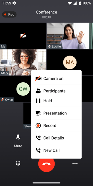
N-WAY Conference
To initiate an N-WAY conference on the WP856 device:
During an ongoing call, click on the conference button.
Add the desired number to the call.
Once the 3rd party answers the call, a 3-way conference will be initiated.
Conference call
One to one Video Call
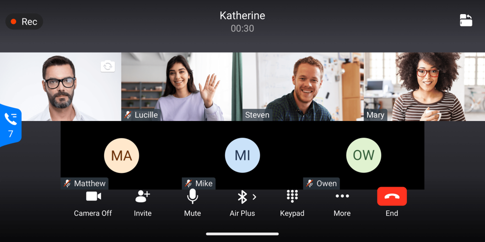
Video Conference Call
Video Conference Landscape Display Orientation
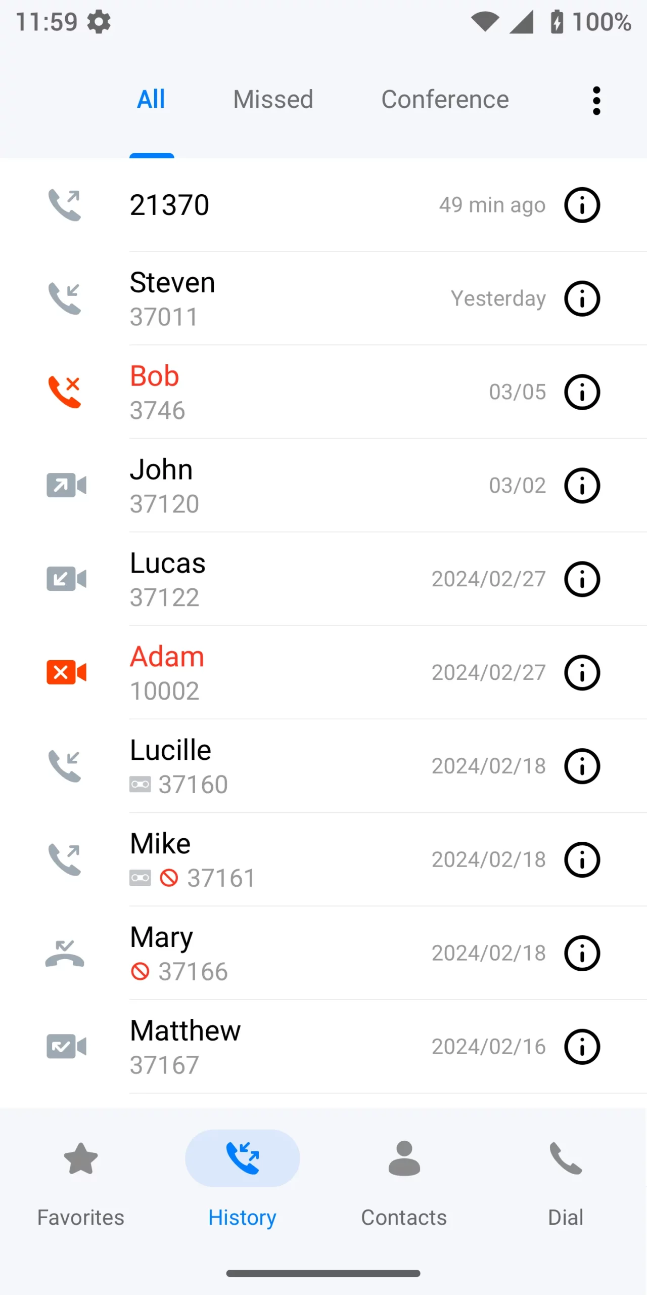
Call History
To access Call History, please follow the steps below:
Click the dial icon on the WP856 home screen
Click on the history tab
Click on All to view all call logs recorded
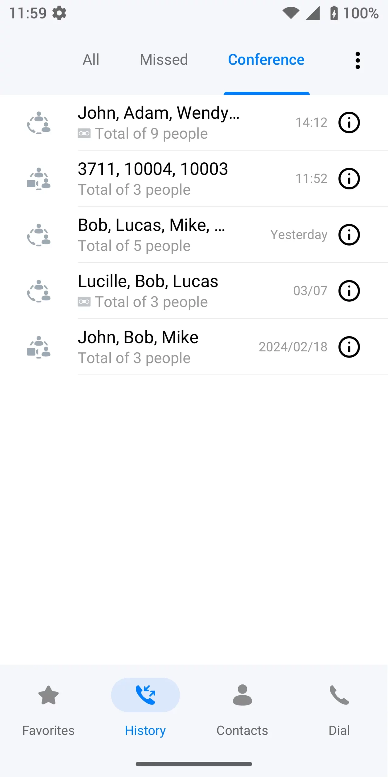
Click on Conference to view conference calls
Click on Missed to view missed calls
Call History
Conference History
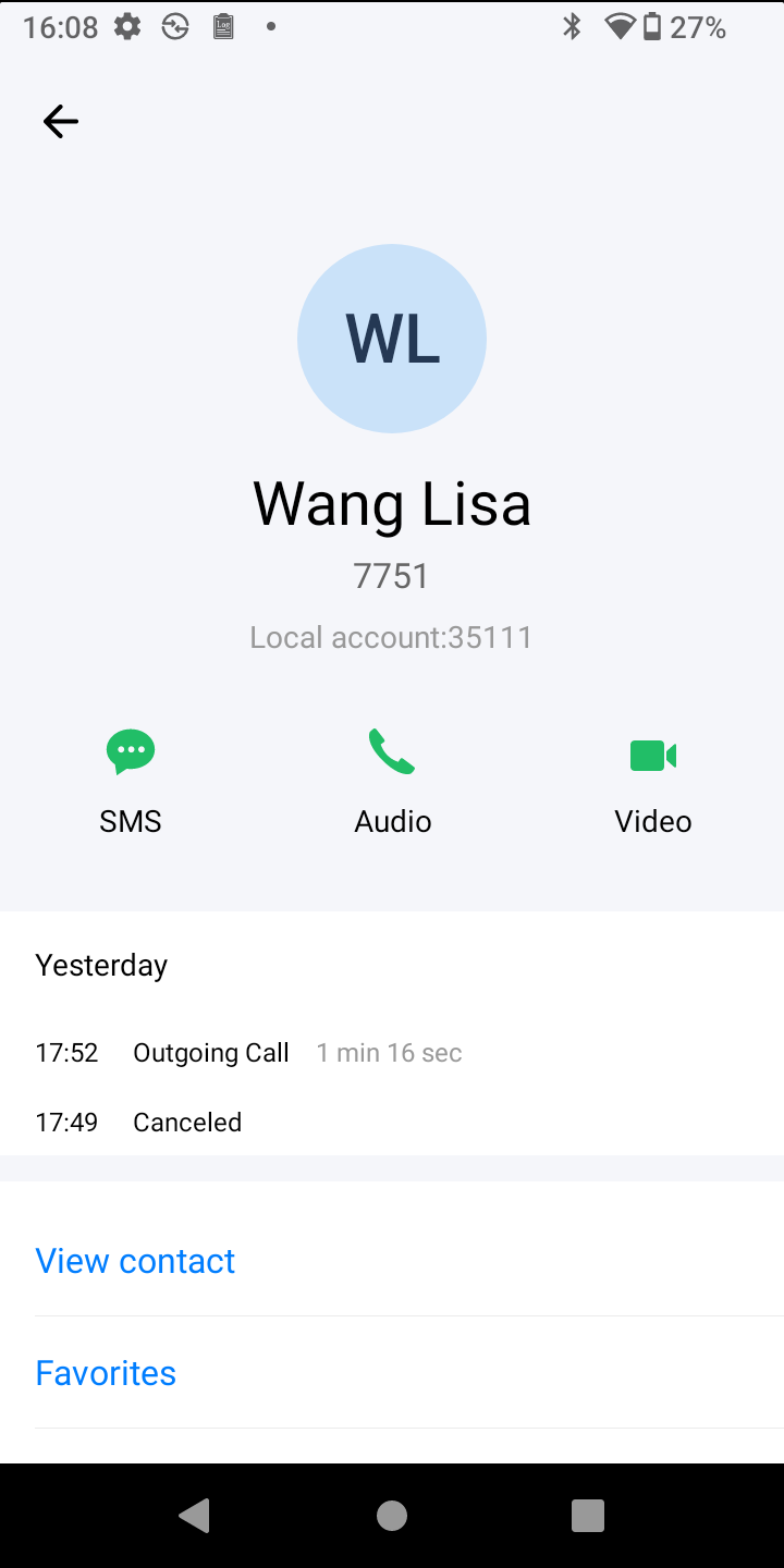
Click on the icon to view more information on the caller
Contact Information
Contacts
Users can access contact lists from the WP856 device, and they can also create new contacts manually.
View Contacts
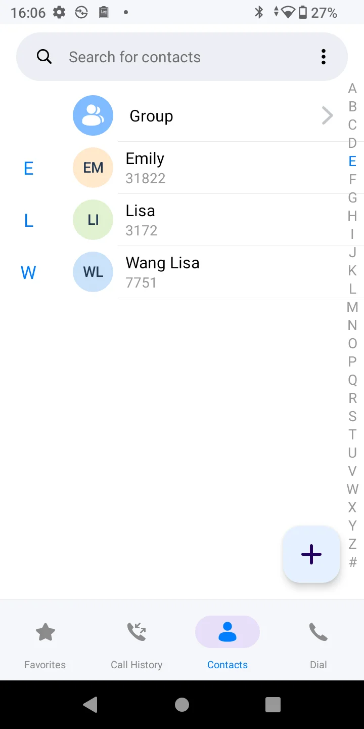
To view the contact list:
Click the dial icon on your WP856 device
Then, hover over to the contacts tab
A list of imported or created contacts will be displayed
Contact Information
Add contacts
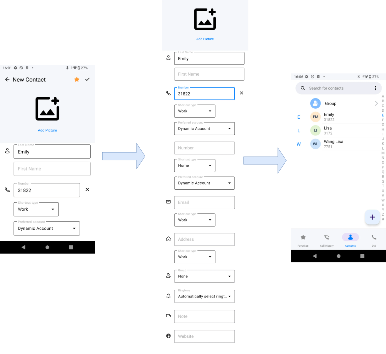
To add a new contact on the WP856 device:
Under the contacts tab, click the icon .
Define the contact fields as displayed below.
Once completed, click save, and the created contact will be added to your contact list.
Add Contact
SMS
Users can send and receive SMS to other extensions using the SMS feature. When opening the messaging application, the user can view all the previous conversations and new messages. The user can tap one of the conversations and start typing the messages in the text box at the bottom of the screen. The user can send up to 500 characters in one message.
By default, there is a maximum of 1000 conversations that can be created on the device. When this limit has been reached, and a new SMS has been received, the device will show the following prompt: “The SMS space is full. The oldest SMS will be deleted to receive new SMS” and the oldest SMS conversations. If the user needs to change this limit, he or she may contact our technical support to change it.
View SMS
To view the list of SMS exchanges, click the icon on the home screen
Click the icon on the home screen
A list of SMS exchanges will be displayed
SMS List
Delete SMS
To delete an SMS
Swipe right on the message you want to delete
Click the icon to delete a message.
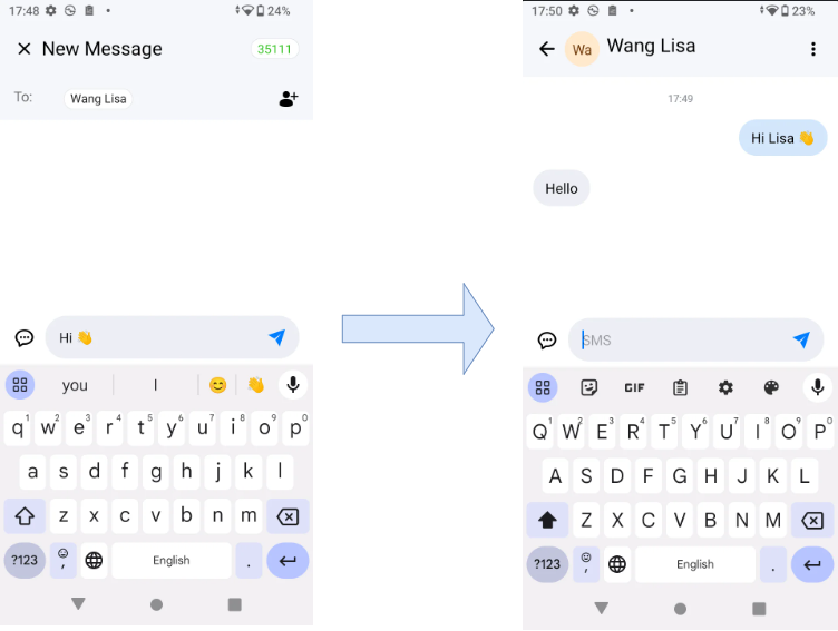
Send SMS
To send a new SMS :
Click the icon to create a new SMS.
Define the receiver’s number or select it from the contact list.
Click the icon , and the message will be sent.
Send SMS
Voicemail
Users can access the list of received voicemails by clicking the icon . Once clicked, it will display a list of received Voicemails, with their corresponding source number and their status (read or unread).
The user must configure an account on the phone to be able to access its voicemail. When the user adds multiple accounts, their voicemails will be displayed in categories as shown in the figure below.
Voicemail List
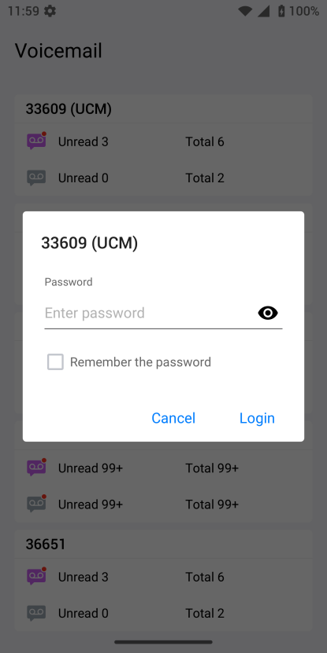
To access the voicemail, the user can tap on the account number that the user wants to access. The user will be prompted to enter the voicemail password. When the correct password is entered, the user will be able to play the voicemail messages.
Voicemail Password Prompt
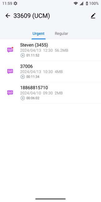
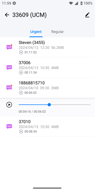
The voicemail messages are displayed as shown in the figure below. The messages are classified into two categories: urgent and regular. The voicemail can then be played directly from this page.
Voicemail Messages
Playing The Voicemail Message
Call Flip
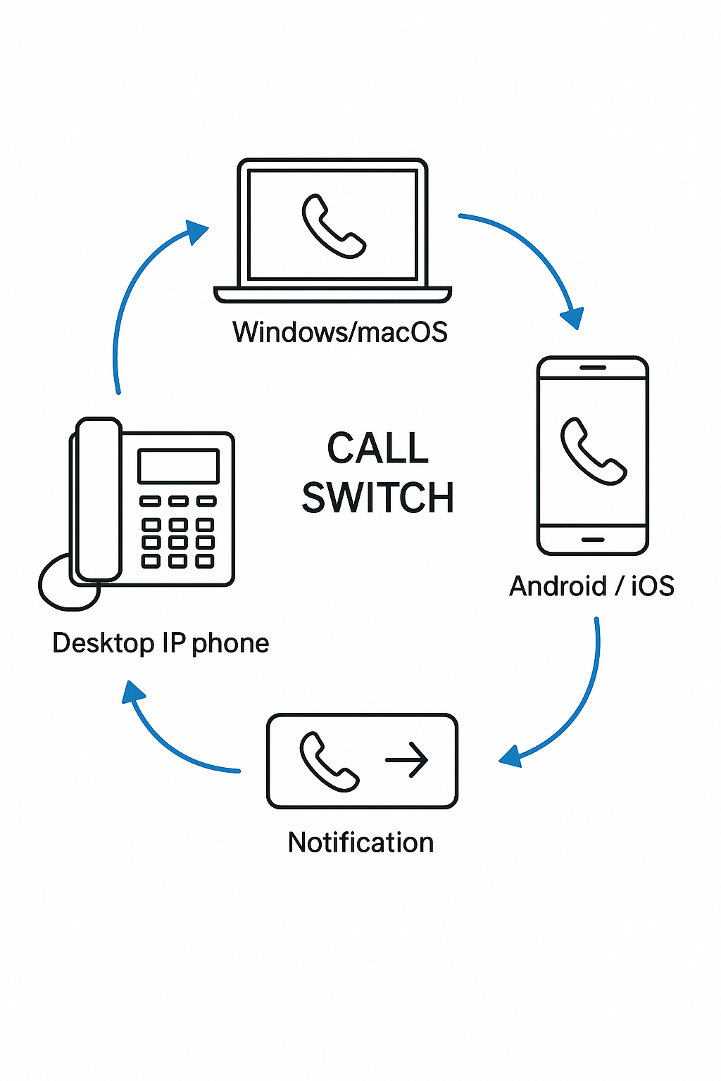
The Call Switch feature provides a convenient way for users to seamlessly transfer an ongoing call between multiple Grandstream devices or applications that share the same SIP account, for example, from a desktop IP phone or team collaboration tool installed on a PC (such as Wave Desktop) to a mobile device, or vice versa.
This feature is especially useful for users who are constantly on the move or work across different devices. For instance, if a call is answered on a PC and the user needs to leave their desk, they can easily switch the call to their WP or smartphone without hanging up or redialing.
When an incoming call is answered on one device, a notification appears on the screen of the other registered devices, giving the user the option to switch the active call to that device. Once the call is switched, the original device automatically terminates the call session, ensuring that only one device remains active on the call.
Call Switch
Supported Scenarios
The account is engaged in a 2-way call or a UCM conference.
The active call can be either audio or video.
Unsupported Scenarios
The account is handling multiple exclusive calls simultaneously with different users.
The account is acting as the host of a local conference call, where switching could disrupt the session.
How to Perform a Call Switch
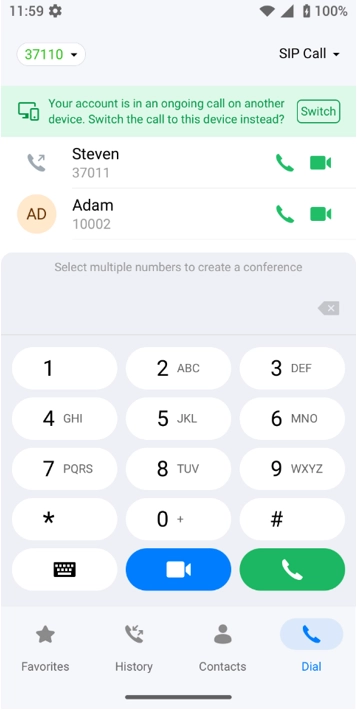
Method 1: Tap the notification bar at the top of the device LCD when prompted. Please see the screenshot below for an example of the notification bar.
Call Flip Prompt
Method 2: Dial the feature code *46 (or a customized code if configured on the UCM server).
CALL RECORDING
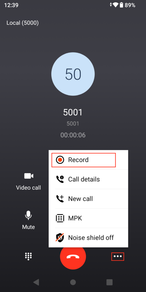
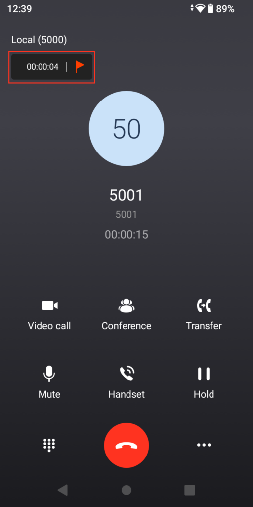
Recording calls is a feature supported by WP856. It can be triggered using the feature code (*3) or it can be done through the graphical user interface, please see the steps below.
During a call, tap the three dots on the bottom right of the screen.
From the menu, tap “Record”, then the call recording will start.
Ongoing Call Record
A small tab will appear on the left side of the screen to indicate that the call is being recorded and the duration of the recording.
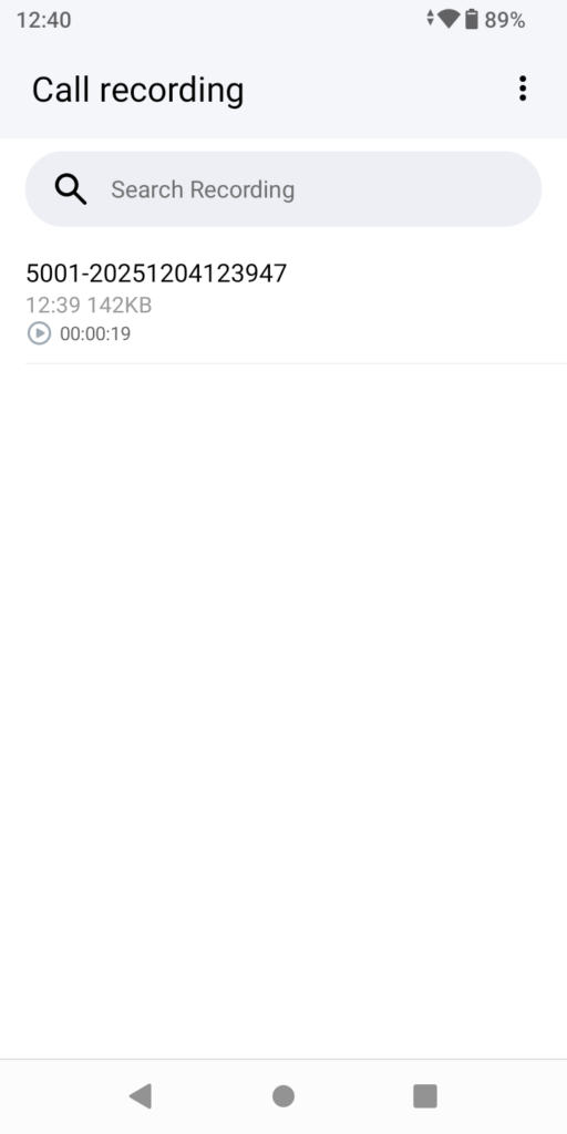
To view the list of previously recorded calls, go to the app launcher, then tap “Call Recording”.
Tap a recording to start listening to it.
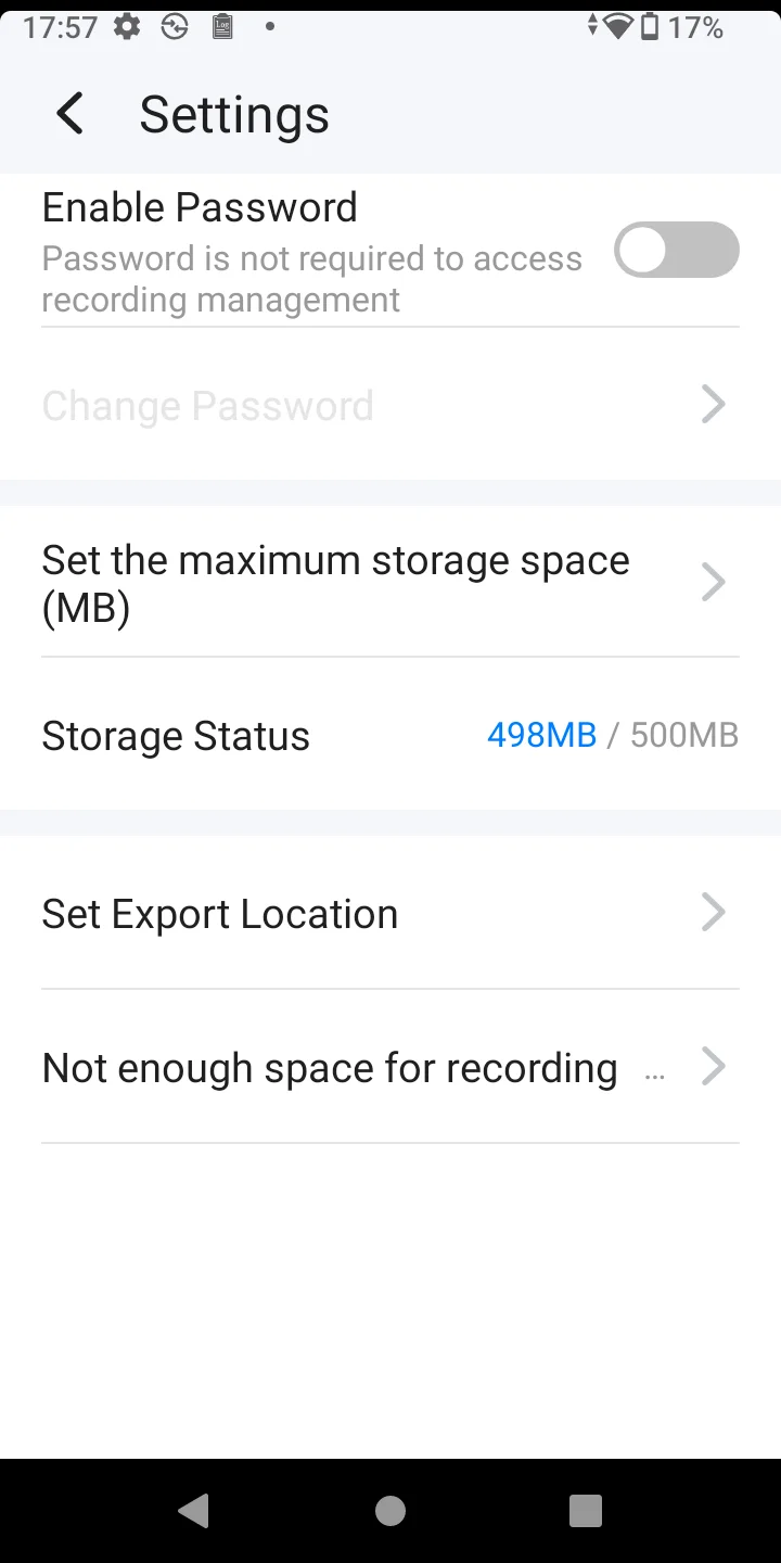
Some additional settings can be configured, such as :
Enable Password: sets a password to access the recording app
Set Maximum storage space: defines the maximum storage dedicated to recording
Set Export Location: Defines where on the system the recording files will be stored
Not Enough Space for recording action: defines how the device will react when there is no space for new recordings, the options are to either replace old recordings with new ones or stop the recordings
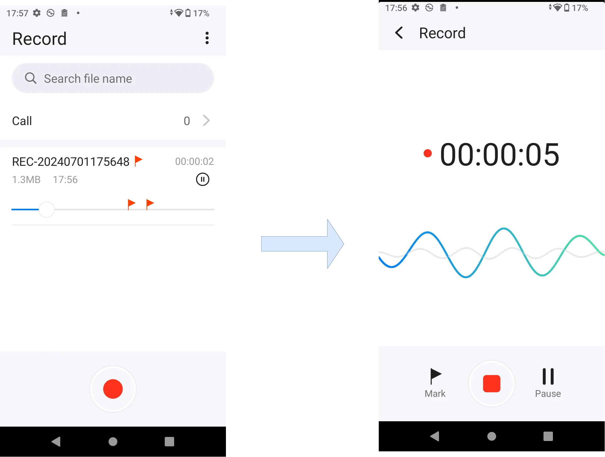
Recording
Recording Settings
SCANNING DEMONSTRATION
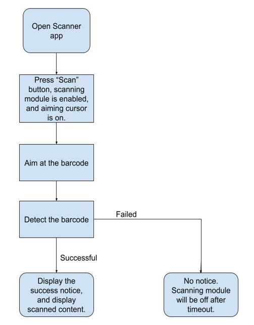
WP856 scans one-dimensional and two-dimensional codes, as well as other information, using its hardware scanning head. The decoded content is then displayed in the scanning demonstration app or the corresponding scanning application app (which can also be a third-party application).
Users can scan barcodes, QR codes, composite codes, and postal codes by pressing the scan button or clicking the scan button on the LCD. After a successful scan, the corresponding barcode information will be displayed in the APP.
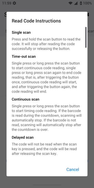
Supports code scanning mode switching :
Single code scanning: Long-press the scan button to read the code; the code reading will stop after successful reading or releasing the button.
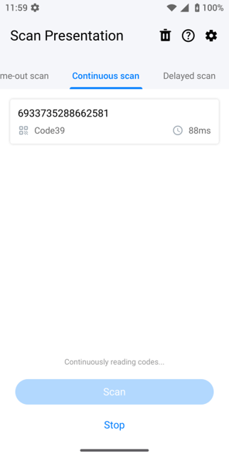
Continuous code scanning: Press the scan button once or long to start continuous scanning, and press it again or long to end code reading. Continuous code reading starts after the button is pressed once. Then the device scanner is on until the button is pressed again to end.
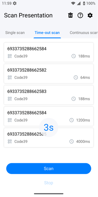
Read code until timeout: Press or hold the scan button to start the countdown. If a barcode is read before the timeout, scanning will automatically stop. If no barcode is detected, scanning will automatically stop after the timeout.
Delayed code reading: The device does not read the code when you hold down the scan button, and reads the code after releasing the scan button.
To access the Scanning Demo application:
On the Menu, launch the Scanning Demo application by clicking the icon .
Press and hold the scan key to scan a code.
Once the code is scanned, the information on the product will be displayed.
If any additional information is required, please click the icon for some usage instructions.
DOOR CONTROL
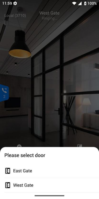
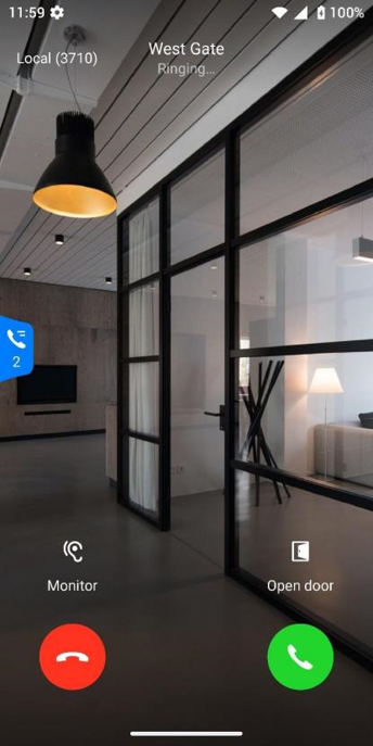
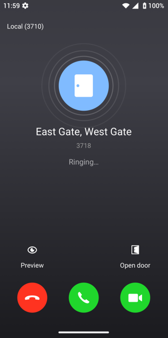
The WP856 can be used to control different door access control devices like our facility access solution, the GDS37XX. Each WP856 device can control up to 10 door access systems. When the doorbell is rung, the phone will switch to door system mode. See the screenshots below for the aforementioned scenario.
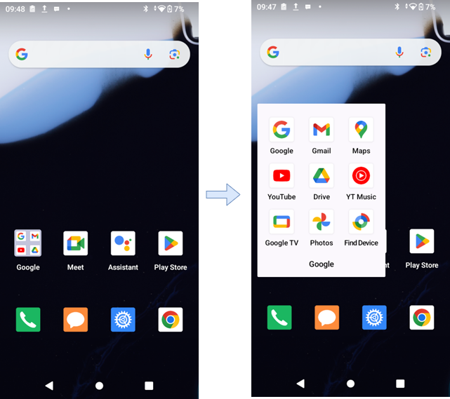
Google GMS Suite Services
Google GMS suite services refer to Google Mobile Services, which is a collection of Google applications and services provided for Android devices. GMS provides users and developers with a series of Google applications and services, including but not limited to:
Google Play Store: A platform for downloading and updating apps.
Google Maps: Provides map and navigation services.
Gmail, YouTube, Google Drive, etc.: Google’s communication and cloud storage services.
Google Photos: A photo and video backup and management service.
Google Files: is a file management application used to clean up storage space and manage files.
GS ODOO APP
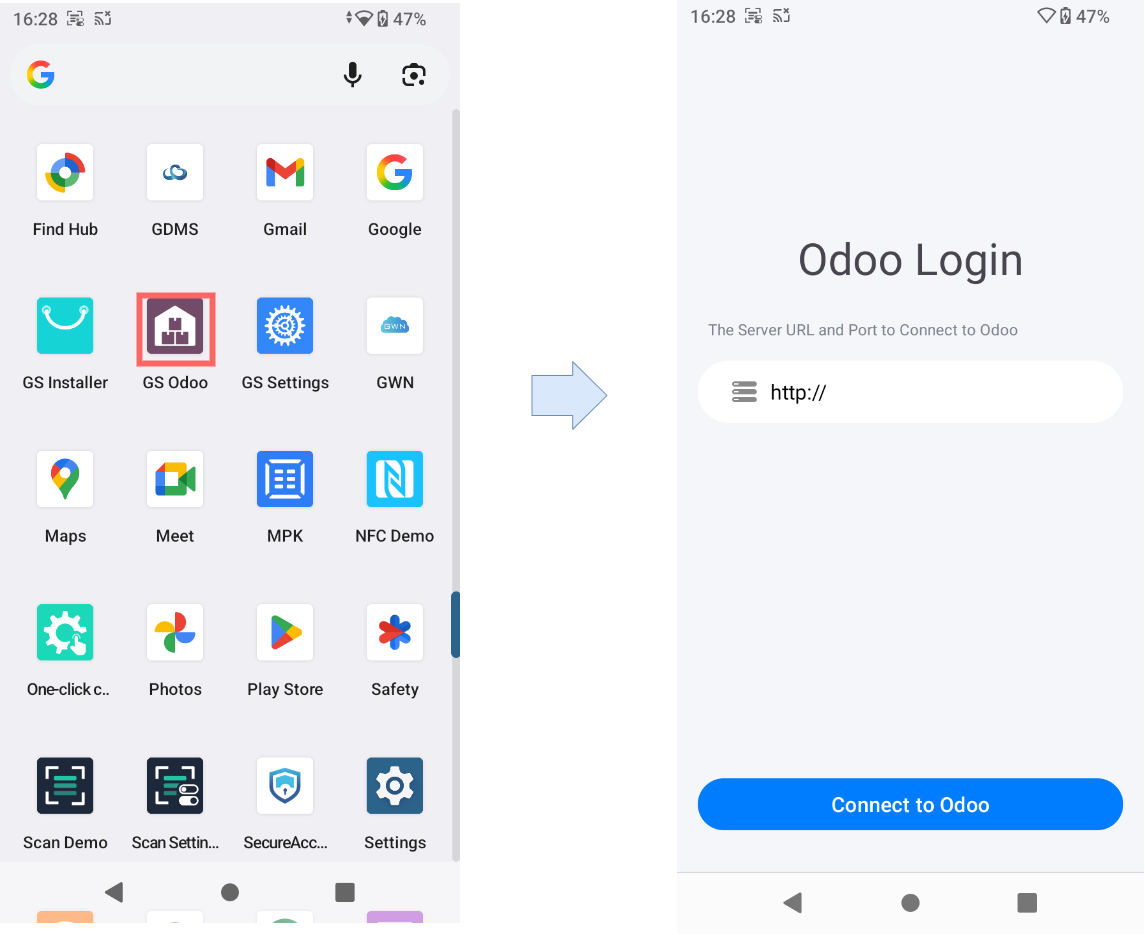
The GS Odoo app is an integrated business management tool available on Grandstream’s WP856 handheld smart terminal. It allows users to connect the device directly to an Odoo ERP (Enterprise Resource Planning) server to streamline access to company data and business operations from the mobile device.
Through the app’s Odoo Login interface, users can enter the Server URL and Port to connect securely to their organization’s Odoo platform. Once connected, the WP856 can access key modules such as inventory, sales, CRM, or field service management, depending on the company’s Odoo configuration.
When integrated, the GS Odoo app transforms the WP856 into a portable ERP terminal, and this enables staff to:
Access real-time company data such as orders, stock, or customer records.
Perform business transactions or updates directly from the device.
Improve mobility and workflow efficiency for on-site or warehouse operations.
GS ODOO APP
BS XSI
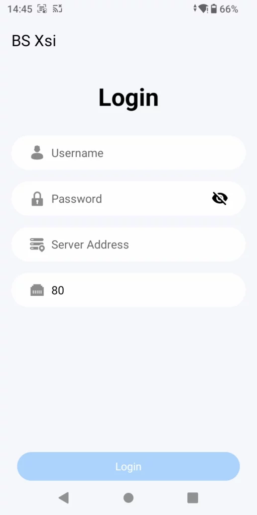
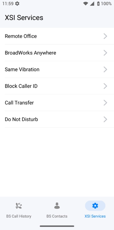
BroadSoft XSI integration allows integrating the phone with a BS XSI server for additional and centrally managed features.
BS Xsi Login Page
XSI Services
ZOOM PHONE PUSH-TO-TALK
Zoom Phone push-to-talk is a feature that simulates a walkie-talkie function where the user can push a button and page another user or group of users. This function requires downloading Zoom application on the phone.
Please refer to the following guide to configure Zoom Phone push-to-talk:
The Status Diagnosis feature on the WP856 provides a built-in diagnostic tool that allows users to check the device’s hardware ports, network connectivity, and audio components. It is designed to help identify system issues and verify proper device functionality without external tools.
The diagnostic tool can be accessed by clicking the icon on the application menu.
General Status
This section displays real-time information about the device’s connectivity and port status:
Port Status: Shows whether key physical interfaces are connected or disconnected.
Type-C: Indicates the connection status of the USB Type-C port.
TF Card: Displays whether a microSD (TF) card is inserted and recognized.
Network Status: Provides details about network connectivity and IP configuration.
Network: Connection type (e.g., Wi-Fi).
IP / Gateway / DNS: Displays IP address, gateway, and DNS server status. “Normal” indicates successful connection and proper configuration.
Account Status: Monitors SIP or account registration status. “Abnormal” indicates that at least one account is not registered correctly.
Retest Button: Re-runs the full diagnostic test to update the displayed results.
General Status
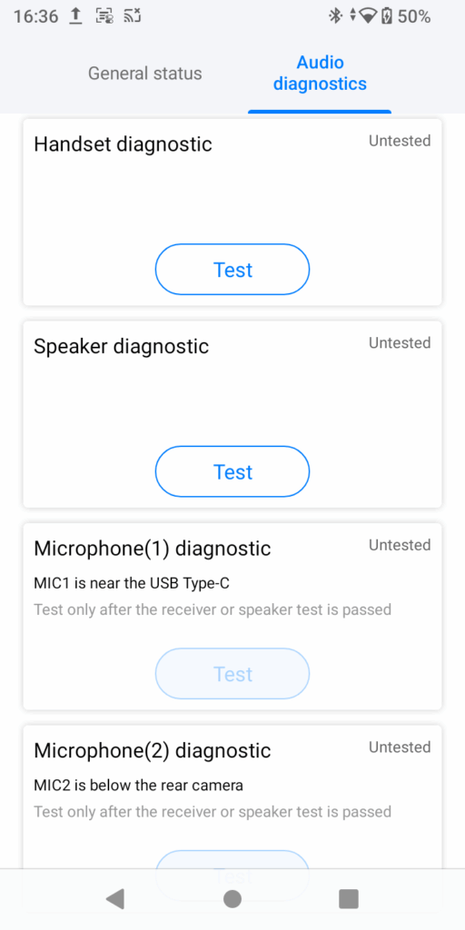
Audio Diagnostics
This section is used to test the WP856’s audio components to ensure proper sound input and output.
Handset Diagnostic: Tests the earpiece (receiver) to confirm proper sound playback during calls.
Speaker Diagnostic: Verifies that the loudspeaker is functioning and can output clear sound.
Microphone (1) Diagnostic: Tests the primary microphone located near the USB Type-C port.
Microphone (2) Diagnostic: Tests the secondary microphone located below the rear camera.
Both microphone tests should be performed after completing the receiver or speaker test to ensure audio paths are functioning properly.
Audio Diagnostics
DIAGNOSTICS
The WP856 device provides a comprehensive and visual overview of network status, account registration, interface status, and sound channels. It features one-click inspections, covering interface, network, and account detection. The interface inspection includes checks on the Type-C port and TD card interface, while the network inspection assesses wireless connectivity, IP address, gateway, and DNS servers. Additionally, it checks the SIP account status for up to six accounts and the outbound proxy. The audio inspection evaluates the receiver, speaker, and microphones by playing and recording sounds, allowing users to verify sound quality and detect any noise issues.
The diagnostic tool can be accessed by clicking the icon on the application menu.
It provides a comprehensive test of the device’s hardware and software components to identify any issues.
System Diagnostics
Ping: Check whether the phone can ping the target host normally.
Traceroute: Check whether the device’s traceroute to the target host is normal.
NSLookup: Test the resolution of a domain name into an IP address
One-key Debug: Tap “Start” to start logging operation information like:
Syslog: used to collect debugging logs for the kernel and services.
Logcat: used to collect debugging Android services and system operations.
Capture Trace: used to capture the network packets and frames.
Secret Key Information: Used to capture the secret key of TLS communications secret key.
Tombstones: Tombstone logs provide more details about events that are logged in Logcat files.
ANR Log: ANR refers to “Application Not Responding”. These files provide logs in the event when an application stops responding.
Battery Log: Log file about the use of the battery by services and application installed on the phone. This log tracks the waking of the apps and their duration of their awake status. It provides also information about the battery life over time.
Record: It provide the media files generated by audio video services of the phone. I.e., the call recordings files.
Core Dump: Provides a snapshot of the memory of the device to investigate the cause behind a process crashing unexpectedly.
Trace Capture in Wi-Fi Monitor Mode:
System Diagnostics
Important
It is highly recommended to run the one-key debug function when collection data for troubleshooting purposes and stop after collecting the files. Otherwise, this may impact the performance and the autonomy of the battery.
Warning
Only share these files with the trusted parties.
Device Diagnostics
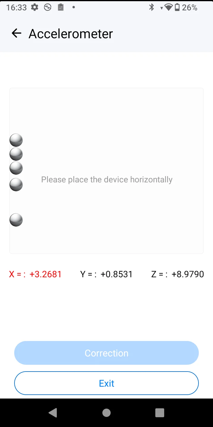
Accelerometer
Tests the device’s accelerometer by detecting and measuring motion and orientation changes.
Accelerometer
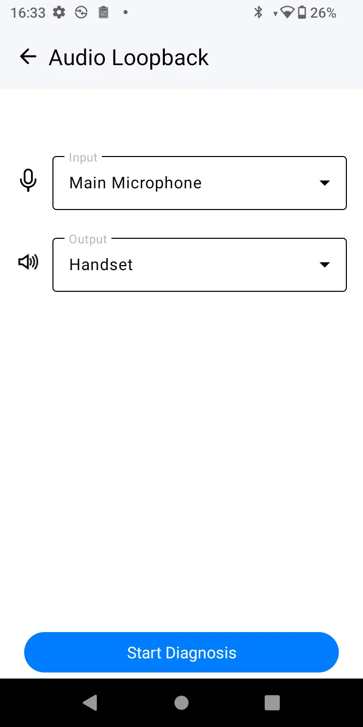
Audio Loopback
Check the audio system by recording and playing back sound to ensure the microphone and speakers are working properly.
Audio Loopback
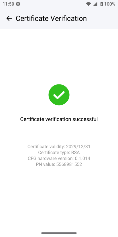
Certificate Check
Verifies the validity and authenticity of security certificates used by the device.
Certificate Check
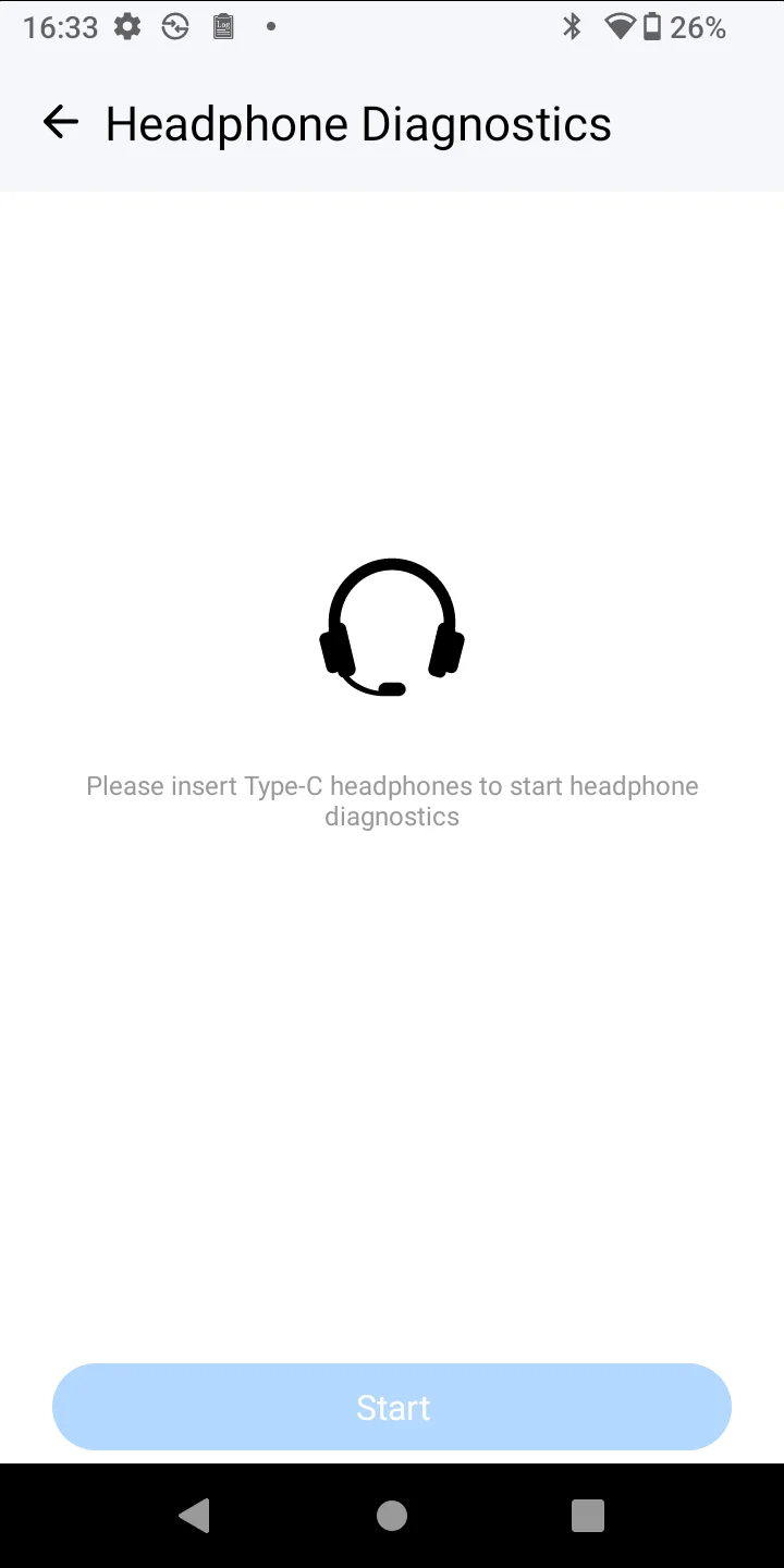
Headphone Diagnostics
Assesses the functionality of the connected headphones by playing sound and recording feedback.
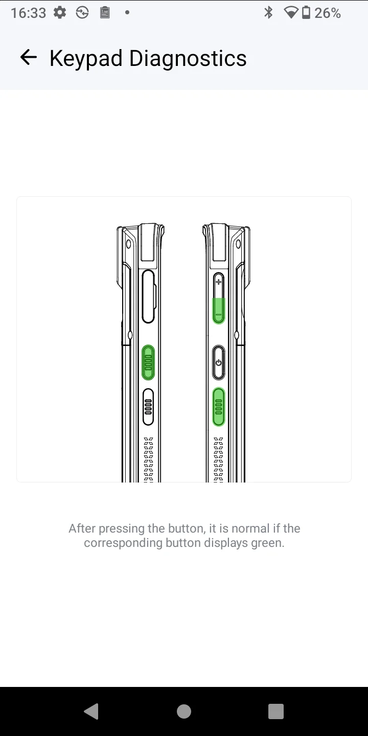
Keypad Diagnostics
Test each side key on the WP856 device to ensure they are responsive and functioning correctly.
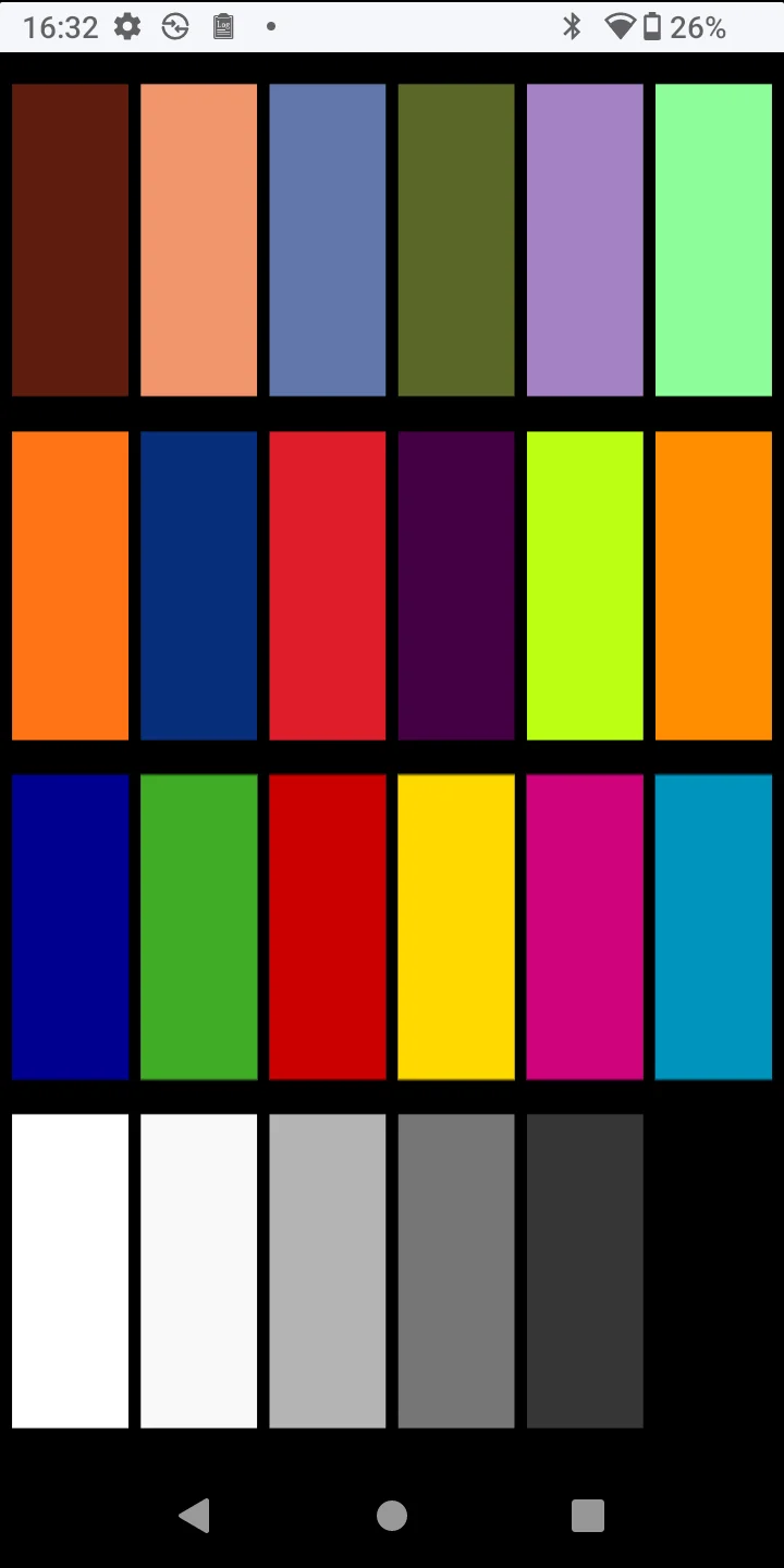
LCD Diagnostics
Checks the display screen for dead pixels, color accuracy, and touch responsiveness.
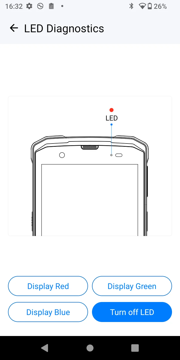
LED Diagnostics
Test the device’s LED lights to ensure they illuminate correctly for notifications and alerts.
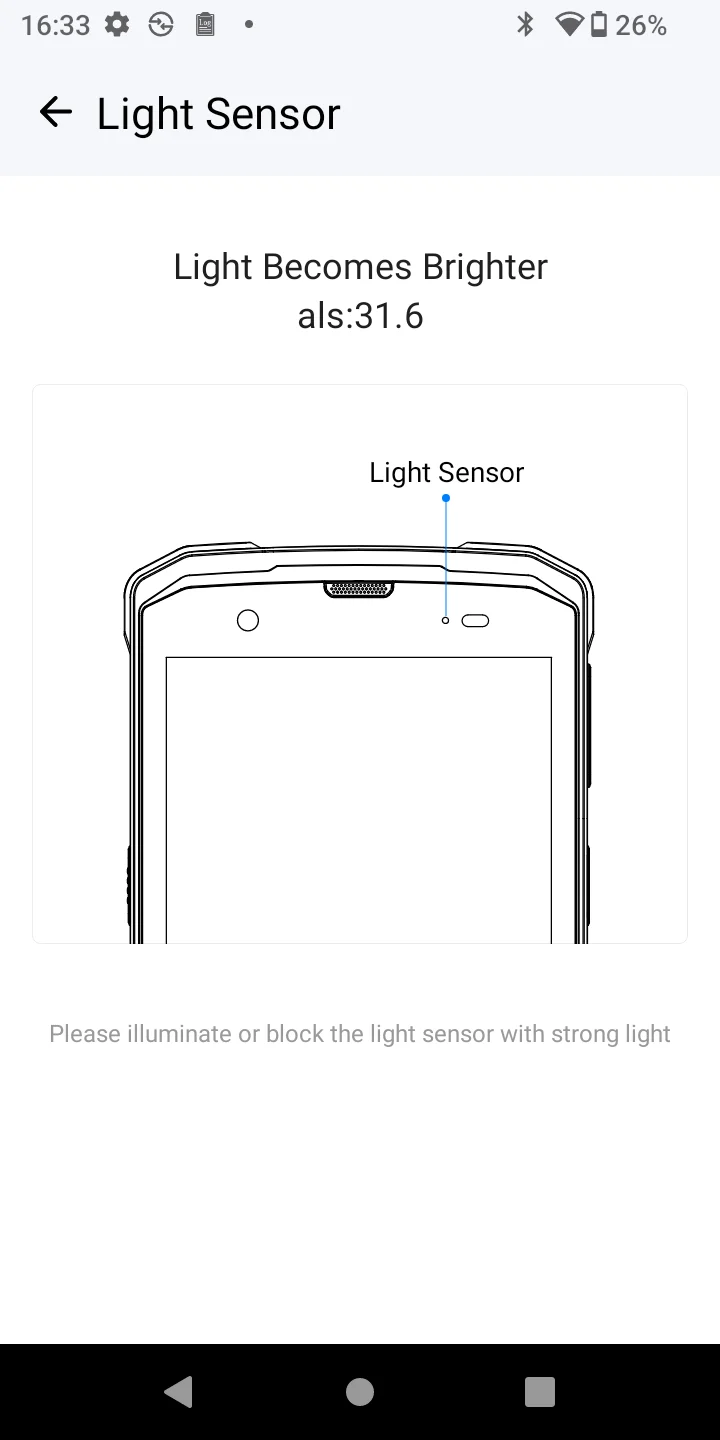
Light Sensor
Evaluates the ambient light sensor’s ability to detect changes in lighting conditions.
Light Sensors
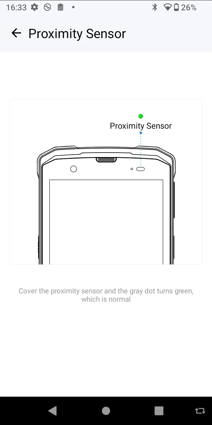
Proximity Sensor
Tests the proximity sensor’s ability to detect when objects are close to the screen, commonly used during calls.
Proximity Sensor
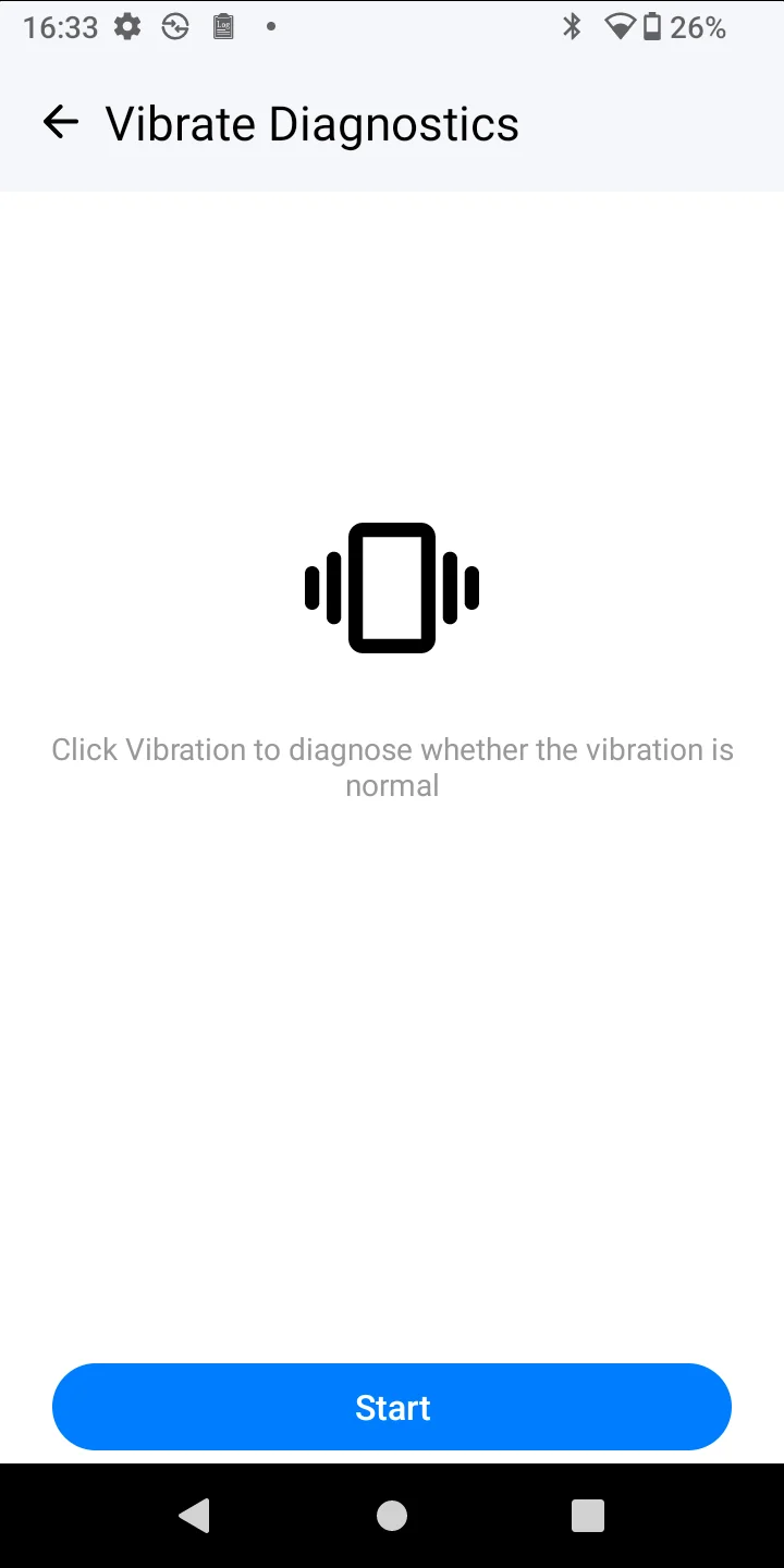
Vibrate Diagnostics
Checks the device’s vibration motor to ensure it operates correctly for notifications and alerts.
Vibrate Diagnostics
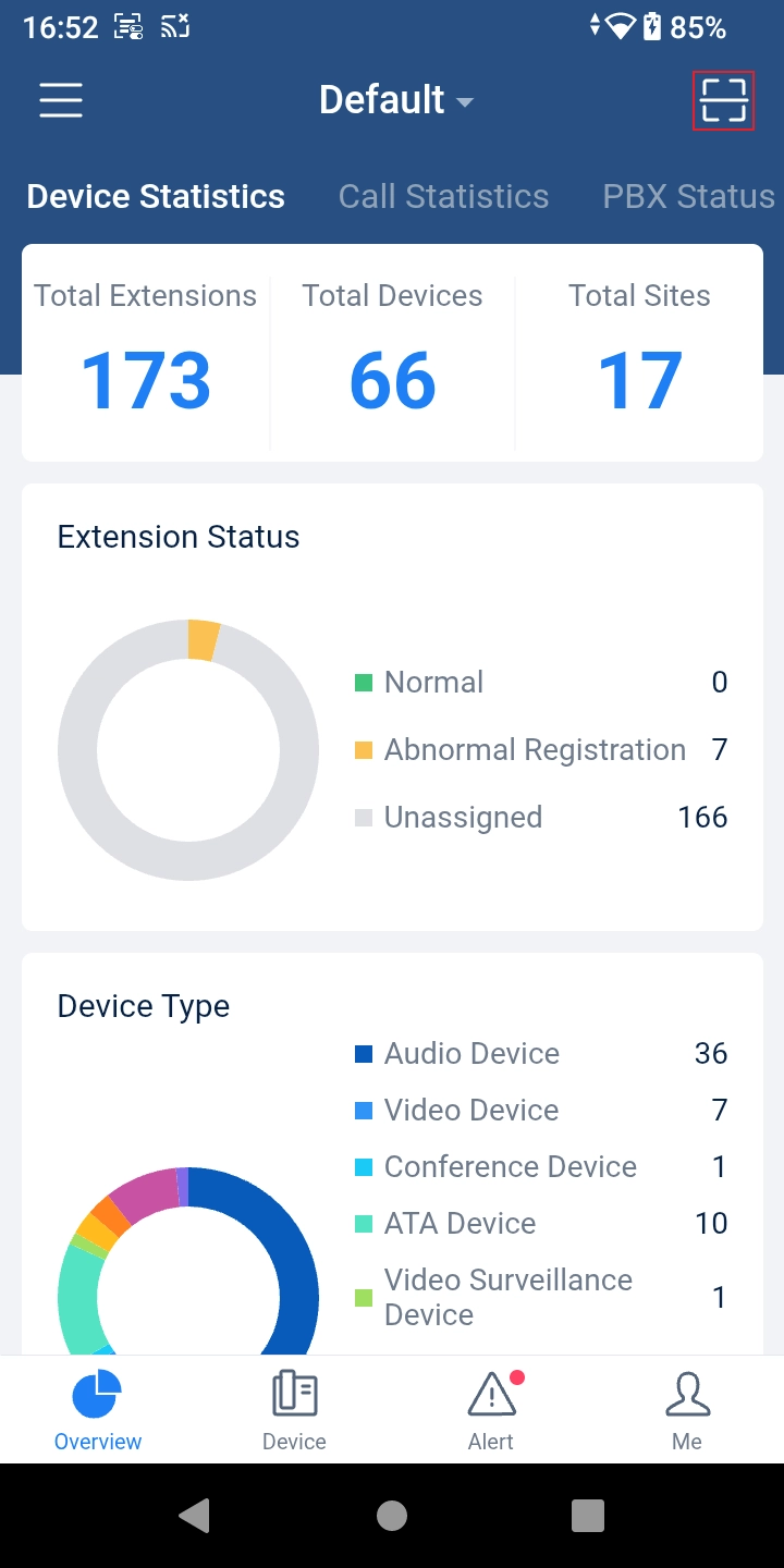
GDMS APP
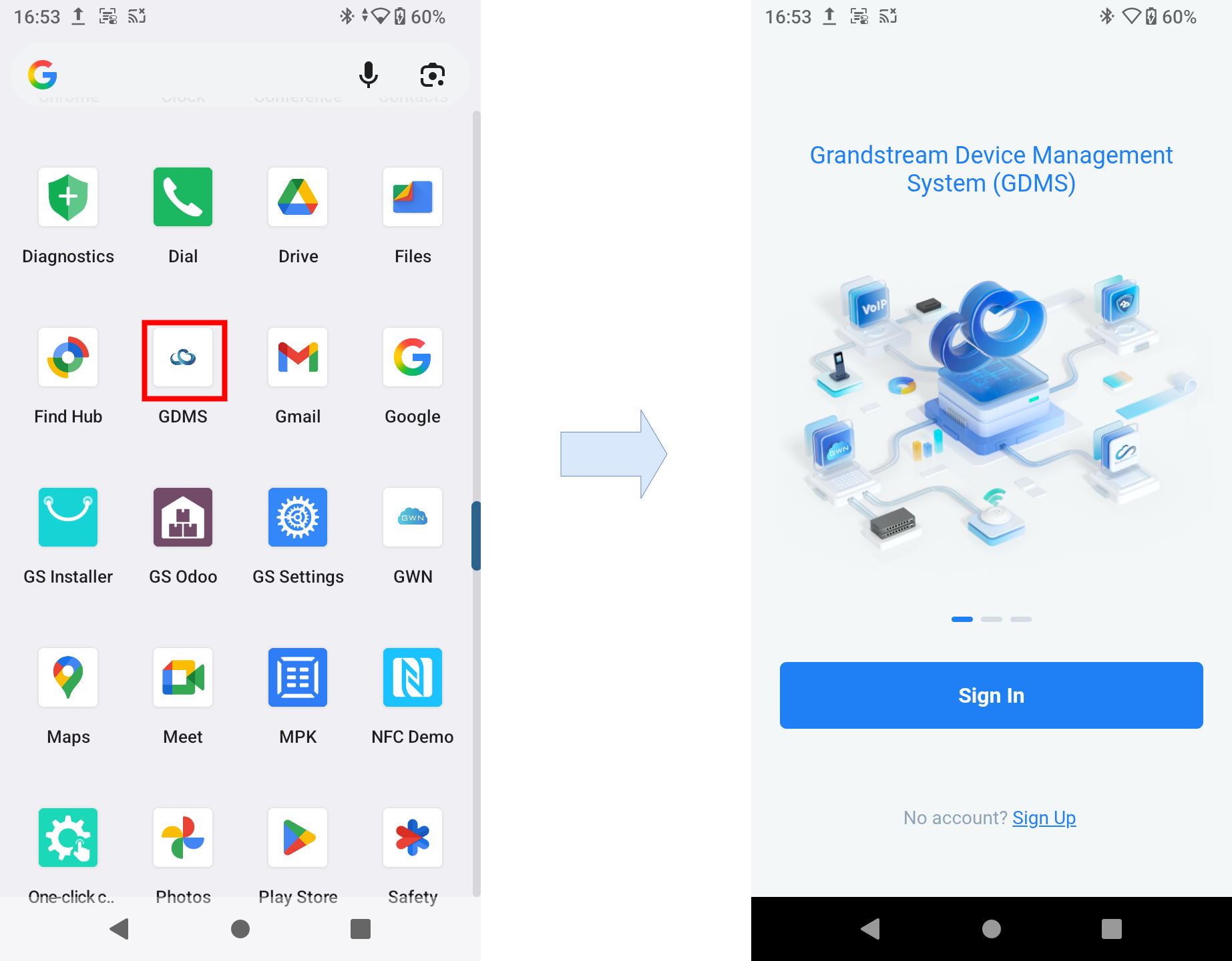
The WP856 device comes pre-installed with Grandstream’s cloud management platform: GDMS (Grandstream Device Management System). This application allows users to remotely manage, monitor, and oversee the operation of all Grandstream devices linked under a single GDMS account.
Through the GDMS app on the WP856, users can sign in and access their device fleet directly from the smartphone, enabling configuration changes, performance monitoring, and troubleshooting, all from one unified interface. This integration transforms the WP856 into a powerful mobile management tool for administrators and IT professionals working with Grandstream solutions.
Cloud Integration
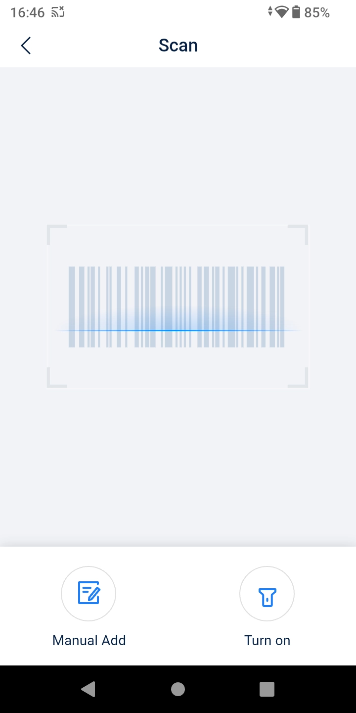
The user can use the phone scanner to add the devices to the GDMS account. Click on to add the devices.
Device Statistics
Scan Device
USB/TF Card Operations
The WP856 supports USB and TF Card connections, which can help provide alternative ways to upgrade the device, install test firmware, or configure the network. In this section of the guide, we will walk you through how this can be done:
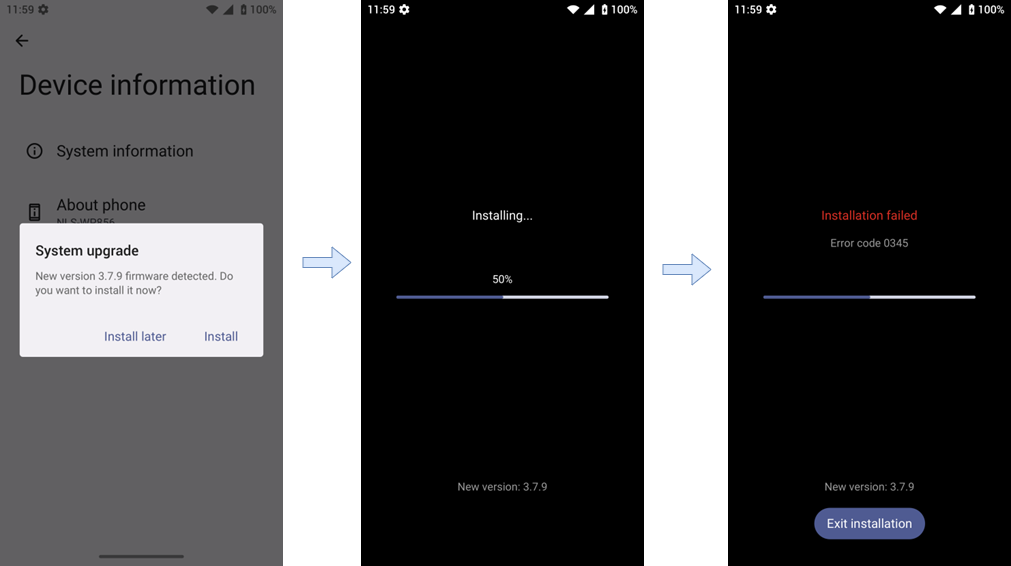
Firmware upgrade via USB/TF card
Put the firmware in the root directory of the USB drive/ TF card or in the warehouse directory, and the version number is different from the current firmware version.
On the LCD, after the new version is detected, a pop-up window will appear to confirm whether to upgrade.
If you pull out the USB disk/TF card during the download process, the upgrade will be interrupted. You can insert it and restart the upgrade normally again.
Unplug the USB drive/TF card during the installation process, and the upgrade can be completed normally.
Firmware upgrade via USBTF card
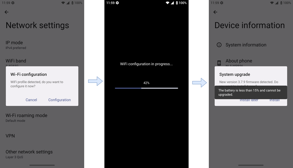
Note
Upgrading will not start if the battery level is below 15%.
USB/TF card configuration file
On the LCD settings, Access GS Settings → Advanced Settings → System Upgrade → USB/TF Card Upgrade Configuration File
When the USB/TF card is connected, after clicking “USB/TF Card Upgrade Configuration File”, the root directory will be traversed to see if the CFG configuration file in the root directory is recognized.
After the configuration file is detected, the user confirms to upgrade the cfg and starts automatic configuration. After applying all the CFG files, it asks whether to reboot immediately to take effect.
USB/SD card Wi-Fi configuration
On the LCD Settings: Go to GS Settings → Network Settings → Configuration Wi-Fi via USB/TF Card.
Place the Wi-Fi configuration installation package wifiAutoConfig.zip in the root directory of the USB drive/SD card.
When the USB/TF card is connected, click “Configuration Wi-Fi via USB/TF Card” to start detecting the configuration file and automatically configure the Wi-Fi.
UPGRADING AND PROVISIONING
The WP856 can be upgraded via TFTP/HTTP/HTTPS by configuring the URL/IP Address for the TFTP/HTTP/HTTPS server and selecting a download method. Configure a valid URL for TFTP, HTTP, or HTTPS. The server name can be an FQDN or an IP address.
There are two ways to set up an upgrade and provisioning on WP856. They are LCD Menu and Web GUI.
Configure via LCD Menu
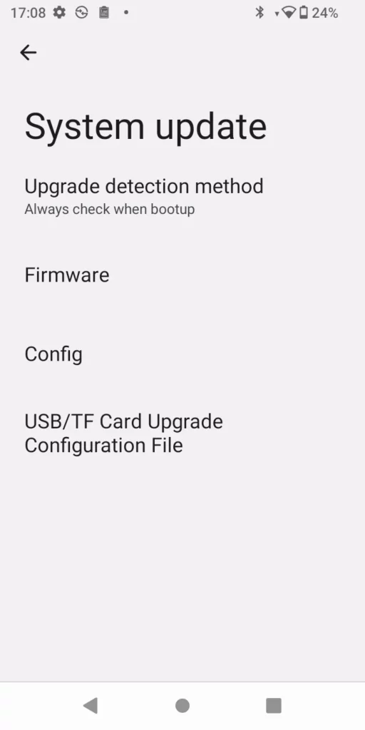
In WP856 Settings, select Advanced Settings → System Update.
Activate the Upgrade Detection method; this will detect if a new firmware or configuration file is available, based on the firmware and config server paths provided.
Configure via LCD Menu
Configure via Web GUI
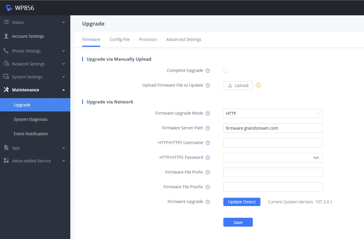
Open a web browser on a PC and enter the IP address for the WP856. Then log in with the administrator username and password. Go to Maintenance → Upgrade → Firmware. In the Upgrade web page, enter the IP address or the FQDN for the upgrade server and choose to upgrade via TFTP, HTTP, or HTTPS (The default setting is HTTPS). Save and apply the changes, press the Upgrade button, or reboot the phone to initiate the firmware upgrade process.
WP856 Upgrade Configuration via Web GUI
Warning
Please do not power off the WP856 when the upgrading process is on.
Upload Firmware Locally
If there is no HTTP(S)/TFTP server, users could also upload the firmware to the WP856 directly via Web GUI. Please follow the steps below to upload firmware to WP856 locally.
Download the latest WP856 firmware file from the following link and save it on your PC. https://www.grandstream.com/support/firmware
Log in to the Web GUI as an administrator on the PC.
Go to Web GUI → Maintenance → Upgrade → Firmware.
Click the “Upload” button, and a window will prompt you to select the firmware file to upload.
Select the firmware file from your PC. Then the uploading progress will show at the button where it was “Upload” in the above step.
When uploading is done, users can see the upgrading process start on the WP856 LCD.
The phone will reboot again with the new firmware version upgraded.
Upload Firmware File to Update
No Local Firmware Servers
Service providers should maintain their own firmware upgrade servers. For users who do not have a TFTP/HTTP/HTTPS server, some free Windows version TFTP servers are available for download from:
Please check our website at https://www.grandstream.com/support/firmware for the latest firmware.
Instructions for local firmware upgrade via TFTP:
Unzip the firmware files and put all of them in the root directory of the TFTP server.
Connect the PC running the TFTP server and the WP856 device to the same LAN segment.
Launch the TFTP server and go to the File → Configure → Security to change the TFTP server’s default setting from “Receive Only” to “Transmit Only” for the firmware upgrade.
Start the TFTP server and configure the TFTP server in the phone’s web configuration interface.
Configure the Firmware Server Path on your WP856 to the IP address of the PC;
Update the changes and reboot the WP856.
Provisioning and Configuration File Download
WP856 SIP Device can be configured via the Web Interface as well as via a Configuration File (binary or XML) through HTTP/HTTPS. The “Config Server Path” is the HTTP or HTTPS server path for the configuration file. It needs to be set to a valid URL, either in FQDN or IP address format. The “Config Server Path” can be the same or different from the “Firmware Server Path”.
A configuration parameter is associated with each particular field in the web configuration page. A parameter consists of a Capital letter P and 1 to 5 (could be extended to more in the future) digit numbers. i.e., P2 is associated with the “Admin Password” in the Web GUI → System Settings → Security Settings → User Info Management page. For a detailed parameter list, please refer to the corresponding firmware release configuration template in the following link:
When the WP856 boots up, it will issue an HTTP(S) request to download a configuration XML file named “cfgxxxxxxxxxxxx.xml”, where “xxxxxxxxxxxx” is the MAC address of the phone, i.e., “cfgec74d700aabb.xml”. If downloading the “cfgxxxxxxxxxxxx.xml” file is not successful, the provision program will download a generic cfg<MODEL>.xml file; if this one fails as well, then it downloads cfg.xml.
The configuration file name should be in lowercase letters.
Restoring the Factory Default Settings will delete all configuration information on the phone. Please back up or print all the settings before you restore to the factory default settings. Grandstream is not responsible for restoring lost parameters and cannot connect your device to your VoIP service provider.
There are two methods to restore the WP856 to the factory default settings :
Restore to Factory Default via the LCD Settings
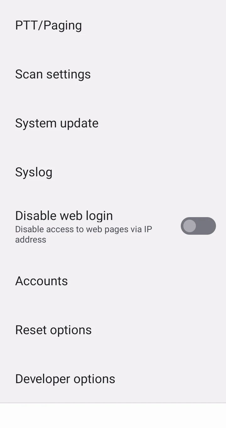
Go to GS Settings → Advanced Settings → Reset options
Select the factory reset option, the device will be rebooted, and after this, all the WP856 data will be erased
Factory Reset from LCD Settings
Restore to Factory Default via the Web GUI
Log in to WP856 Web GUI and go to Maintenance → Upgrade →Advanced Settings.
At the bottom of the page, click on the Reset button for a Factory reset.
WP856 Web GUI Factory Reset
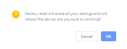
A dialog box will pop up to confirm the factory reset.
Click OK to restore the phone to factory settings.
WP856 Web GUI Confirm Factory Reset
SDK INTERFACE
The WP856 operating system is developed based on the Android TM platform. In addition to inheriting the functional interface of Android, it also provides an interface for third-party application development according to user needs.
This section documents significant changes from previous firmware versions. Only major new features or major document updates are listed here. Minor updates for corrections or editing are not documented here.
Firmware Version 1.0.3.16_GS_207.0.3.16
Updated the valid input range under GS Settings → Intelligent Assistance → Simulate Keyboard Input. [Simulate Keyboard key]
Enhanced multi-scan behavior by adding support for “Always output to last field” in Scan Settings → Profile → Output Mode → General Settings. [Always output to last field]



 then click Remote Access to Web UI.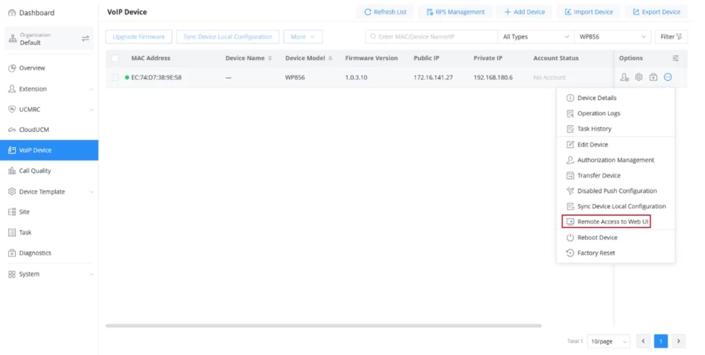




 : When tapping this icon, the user can choose the front or the back camera.
 : When tapping this icon, the user can switch the display orientation of the phone from portrait to landscape, or vice versa.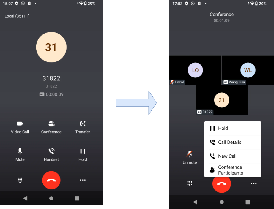






 . Once clicked, it will display a list of received Voicemails, with their corresponding source number and their status (read or unread).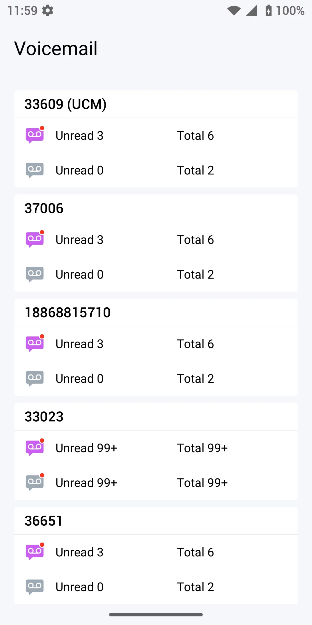


 on the application menu.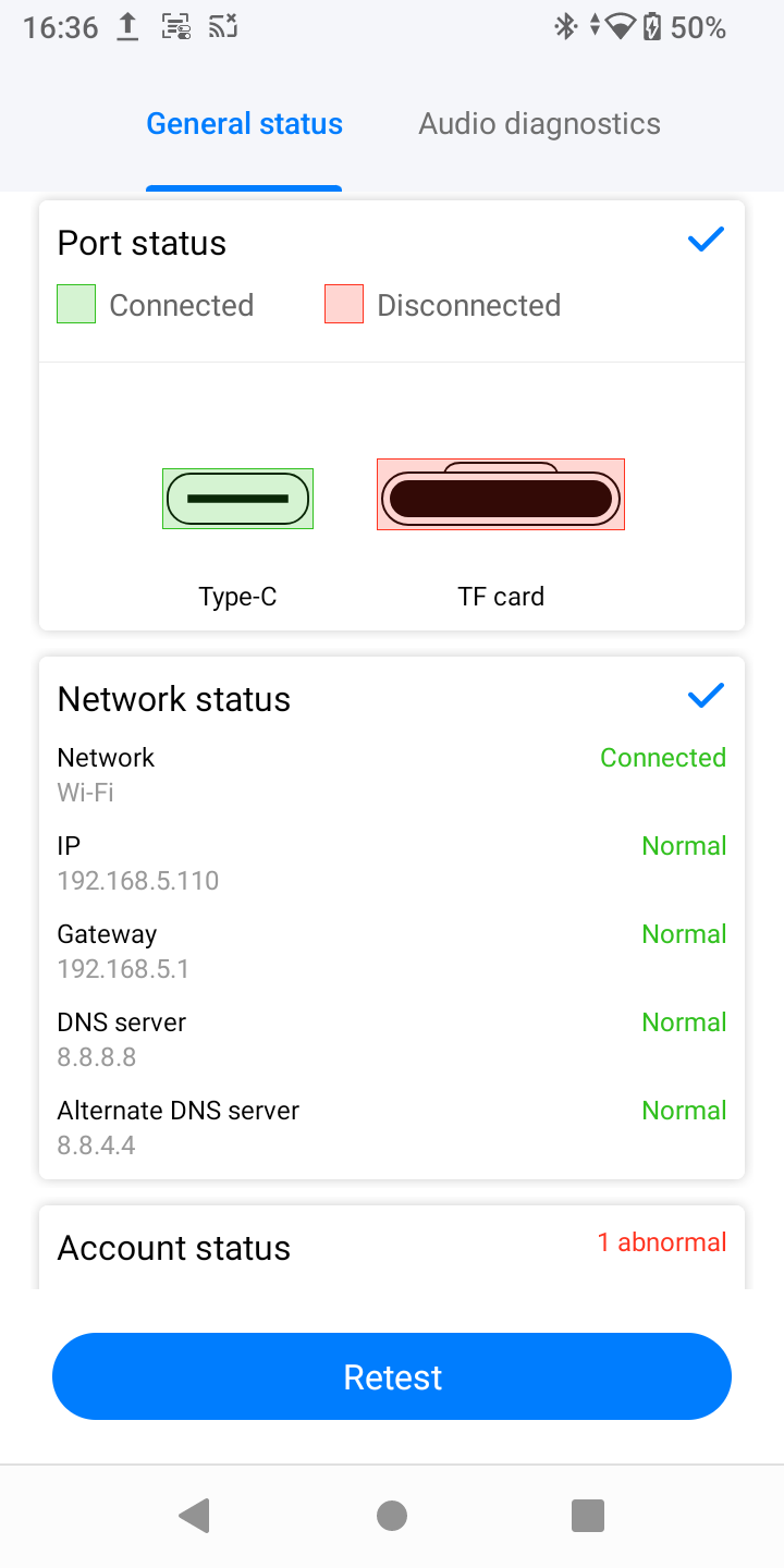
 on the application menu.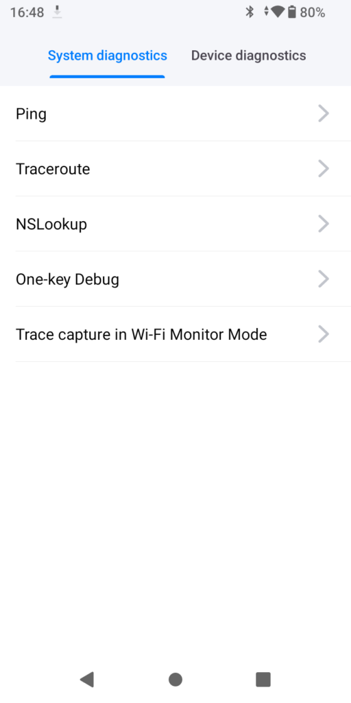
 to add the devices.