


The GWN7062M is a high-performance, secure dual-band Wi-Fi 6 (802.11ax) router designed to deliver fast, reliable, and flexible network connectivity for modern homes, small offices, and commercial environments. Powered by a 1.3GHz dual-core processor, it supports combined Wi-Fi speeds of up to 3Gbps and up to 256 concurrent wireless clients, ensuring smooth performance for bandwidth-intensive activities such as 4K UHD streaming, video conferencing, online gaming, and smart automation.
The router features one 2.5G combo port, one WAN/LAN auto-sensing port, one 2.5G LAN, and two 1G LAN ports to provide flexible high-speed wired connectivity and simplified network expansion. Equipped with Wi-Fi 6 MU-MIMO and beamforming technology, the GWN7062M delivers extended coverage, improved efficiency, and reduced latency for all connected devices.
It supports wireless Mesh networking with other Grandstream routers, ensuring seamless roaming and easy Wi-Fi expansion. For enhanced security, the GWN7062M features advanced firewall protection, multiple encryption protocols, and enterprise-grade security measures, including unique device certificates and random default passwords.
Comprehensive VPN support (including L2TP, PPTP, IPSec, OpenVPN®, and WireGuard®) allows secure remote connectivity, while intelligent QoS and Deep Packet Inspection (DPI) optimize traffic flow and ensure consistent performance.
Management is simple and flexible through the built-in Web GUI, GDMS Networking, and GWN Manager for both cloud and on-premise control. Users can also manage the router conveniently via the Grandstream Home App, providing an intuitive mobile experience for monitoring and configuration.
By combining high-speed Wi-Fi, intelligent management, advanced security, and multi-Gigabit connectivity, the GWN7062M offers a reliable and scalable networking solution for today’s connected environments.
PRODUCT OVERVIEW
Technical Specifications
Hardware Specifications
Radio | Antenna | 5 single frequency antennas: 2.4GHz: gain 5dBi 5GHz: gain 5dBi |
MU-MIMO | 2.4GHz: 2×2:2 5GHz: 3×3:2 | |
Frequency Bands | 2.4GHz radio: 2400–2483.5 MHz 5GHz radio: 5150–5895 MHz (*Not all frequency bands can be used in all regions) | |
Channel Bandwidth | HT20/40, VHT20/40/80, HE20/40/80/160 | |
Wi-Fi Data Rates | 5G: IEEE 802.11ax: 7.3 Mbps to 2402 Mbps IEEE 802.11ac: 6.5 Mbps to 1732 Mbps IEEE 802.11n: 6.5Mbps to 300Mbps IEEE 802.11a: 6, 9, 12, 18, 24, 36, 48, 54 Mbps 2.4G: IEEE 802.11ax: 7.3 Mbps to 573.5 Mbps IEEE 802.11n: 6.5Mbps to 300Mbps IEEE 802.11b: 1, 2, 5.5, 11 Mbps IEEE 802.11g: 6, 9, 12, 18, 24, 36, 48, 54 Mbps *Actual throughput may vary depending on many factors including environmental conditions, distance between devices, radio interference in the operating environment and mix of devices in the network. | |
Maximum TX Power | 2.4G: 24 dBm 5G: 26 dBm (*Maximum power varies by country, frequency band and MCS rate) | |
Receiver Sensitivity | 2.4G 802.11b: -96dBm@1Mbps, -88dBm@11Mbps; 802.11g: -93dBm@6Mbps, -75dBm@54Mbps; 802.11n 20MHz: -73dBm@MCS7; 802.11n 40MHz: -70dBm@MCS7; 802.11ax 20MHz: -60dBm@MCS11; 802.11ax 40MHz: -58dBm@MCS11; 5G 802.11a: -92dBm@6Mbps, -74dBm@54Mbps; 802.11n 20MHz: -73dBm@MCS7; 802.11n 40MHz: -70dBm@MCS7; 802.11ac 20MHz: -67dBm@MCS8; 802.11ac 40MHz: -63dBm@MCS9; 802.11ac 80MHz: -59dBm@MCS9; 802.11ax 20MHz: -60dBm@MCS11 802.11ax 40MHz: -58dBm@MCS11; 802.11ax 80MHz: -56dBm@MCS11; 802.11ax 160MHz: -52dBm@MCS11; | |
Coverage Range | 150 square meters (*Coverage range can vary based on environment) | |
Interfaces | Network Ports | 1x 2.5G Combo SFP/RJ45 Ethernet WAN; 1x autosensing 10/100/1000Mbps Ethernet WAN/LAN, RJ-45; 1× 2.5G Ethernet LAN (RJ-45); 2× 1G Ethernet LAN (RJ-45) 1x USB 2.0 port (Supports USB LTE dongle device as USB WAN) |
LEDs | 1 tri-color LED and 8 single-color LEDs | |
Auxiliary Ports | 1× Reset Pinhole, 1× SYNC, 1× POWER | |
Power | Maximum Power Consumption | 18W |
Physical | Dimensions | Unit: 205mm (L) × 130mm (W) × 35.5mm (H); Entire Package: 356mm(L) x 309.5mm(W) x 62mm(H) |
Weight | Unit: 400g Entire Package: 855g | |
Mounting | Desktop or indoor wall mount | |
Package Content | GWN7062M router, Power Adapter, Ethernet Cable, Quick Installation Guide | |
Environmental | Temperature | Operation: 0°C to 45°C; Storage: -30°C to 60°C |
Humidity | 10% to 90% Non-condensing | |
Compliance | FCC, CE, RCM, IC | |
GWN7062M Hardware Specifications
Software Specifications
Wi-Fi Standards | IEEE 802.11 a/b/g/n/ac/ax | |
SSIDs | • 4 host SSIDs + 1 guest SSID; • restrict access and improve security by SSID hiding; • dynamic radio power and channel assignment | |
Concurrent Wireless Clients | Up to 256 clients | |
Working Mode | • Router Mode • Wireless Bridge Mode • Wireless Relay Mode | |
Mesh | Supports Mesh networking with up to 3 devices, and the supported models are: GWN7062M, GWN7062E, GWN7062ET and GWN7660EM | |
WAN | • Internet connection types: Static IP, DHCP, PPPoE, PPTP, L2TP • supports Dual WAN, Failover, and Load Balance policy | |
LAN | • DHCP server • manually bind IP address • supports VLAN and assigning VLAN to port | |
ISP | • Supports IGMP • IPTV/VoIP/Triple Play • customized WAN-side VLAN settings | |
VPN | Supports 8 VPN tunnels total: • L2TP Client • PPTP Client • IPSec Site-to-Site & Client-to-Site • OpenVPN® Server • WireGuard® Site-to-Site & Peer-to-Site | |
Encryption | Open system WPA/WPA2 WPA2 WPA2/WPA3 WPA3 anti-hack secure boot and critical data/control lockdown via digital signatures; unique security certificate and random default password per device | |
Parental Control | • Safe Search • Customized Internet Schedule • Up to 32 Parental Control Clients • Website Filtering • APP Filtering • URL Blocklist | |
QoS | • Supports 8 queues with multiple traffic priority and bandwidth • APP QoS • QoS rules | |
Traffic Statistics | Application monitoring and traffic statistics with DPI Analysis period: Daily, Weekly, Monthly | |
Firewall | DoS attack defense Blocklist | |
NAT | DDNS Port Forwarding DMZ UPnP | |
Content Control | • URL Filtering • URL Classification Filtering • APP Filtering | |
Access Control | Supports WAN side access control and IP address restrictions | |
Captive Portal | Supports social login, vouchers, password authentication | |
Maintenance | • Configuration Backup and Restore • Diagnosis tools • Feedback System • System Log • Intelligent Detection • Auto Firmware Update | |
Management Platform | • Embedded controller can manage itself and the Mesh Node • GDMS (Networking) offers a free cloud management platform for unlimited GWN Routers • GWN Manager offers premise-based software controller • Grandstream Home App offers a unified mobile management platform for easy control • TR-069 | |
GWN7062M Software Specifications
Service Ports
The following service ports are used by the router. These ports enable features such as remote management, device discovery, secure UI access, and portal-based authentication services:
Port | Protocol | Description |
14 | UDP | Used for automatic discovery of GWN Access Points within the local network (proprietary protocol). |
53 | UDP | Built-in DNS service for hostname resolution on the local network. |
80 | TCP | HTTP access; used as an initial entry point and redirects to HTTPS (port 443). |
443 | TCP | HTTPS web interface; provides secure access to the GWN management UI. |
8080 | TCP | Captive portal redirect for guest access and authentication workflows. |
8443 | TCP | Encrypted web authentication; used for secure access to captive portal and guest services. |
9443 | TCP | Business portal services, such as voucher-based log downloads and extended access features. |
22 | TCP | Secure Shell (SSH) used for CLI access and remote command-line management. |
Service Ports
INSTALLATION
Before deploying and configuring the router, the device needs to be properly powered up and connected to the network. This section describes detailed information on the installation, connection, and warranty policy of the router.
Package Contents
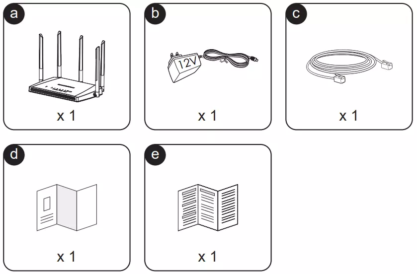
Powering and Connecting
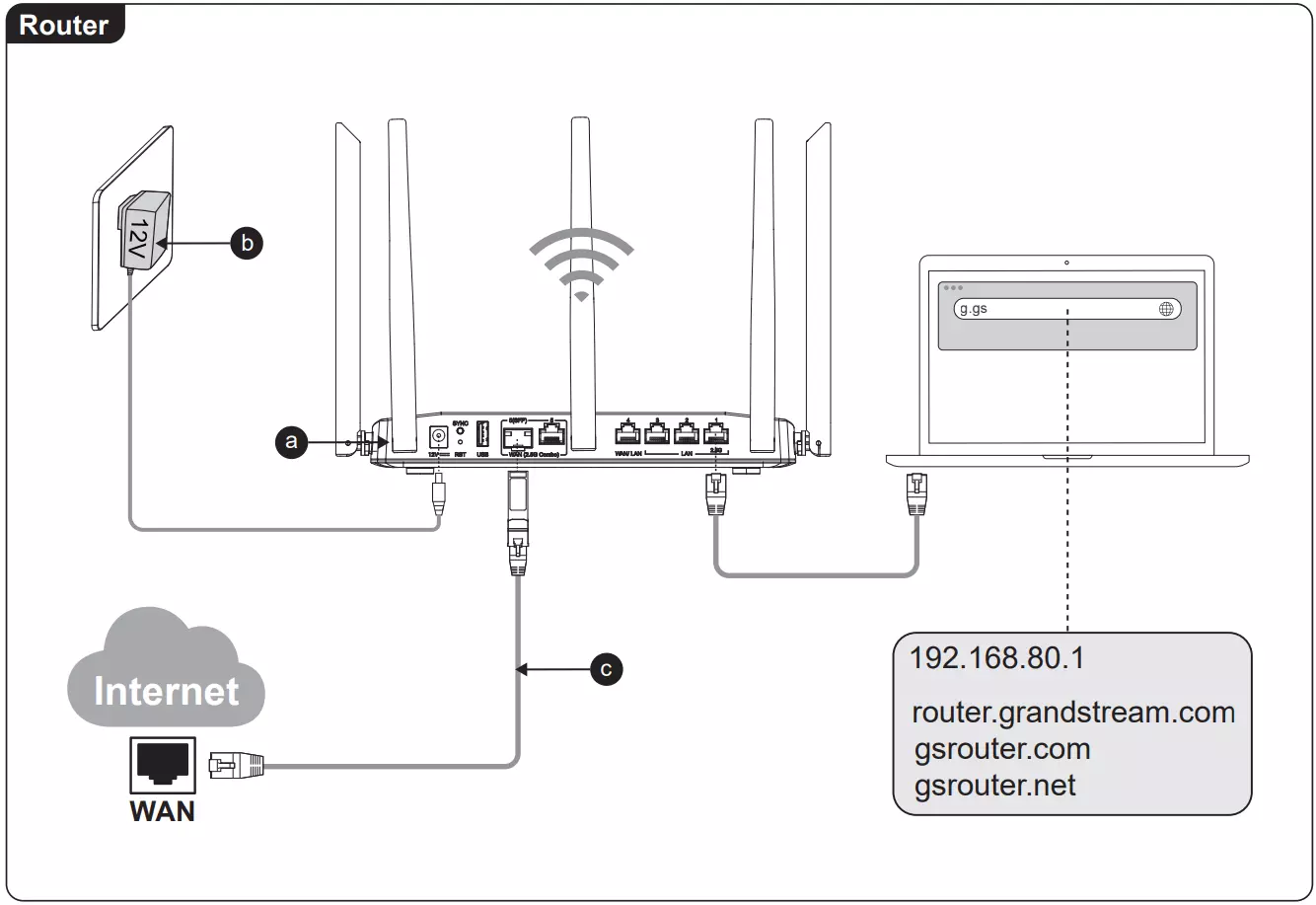
This section explains how to properly connect the GWN7062M to power, WAN, and devices.
- Connect the WAN port to the uplink.
- Plug in the power adapter and turn the unit on.
- Wait until the device is powered up and Wi-Fi is active (Wi-Fi LEDs will blink).
- Use a computer or mobile device to connect to the default SSID or LAN port.
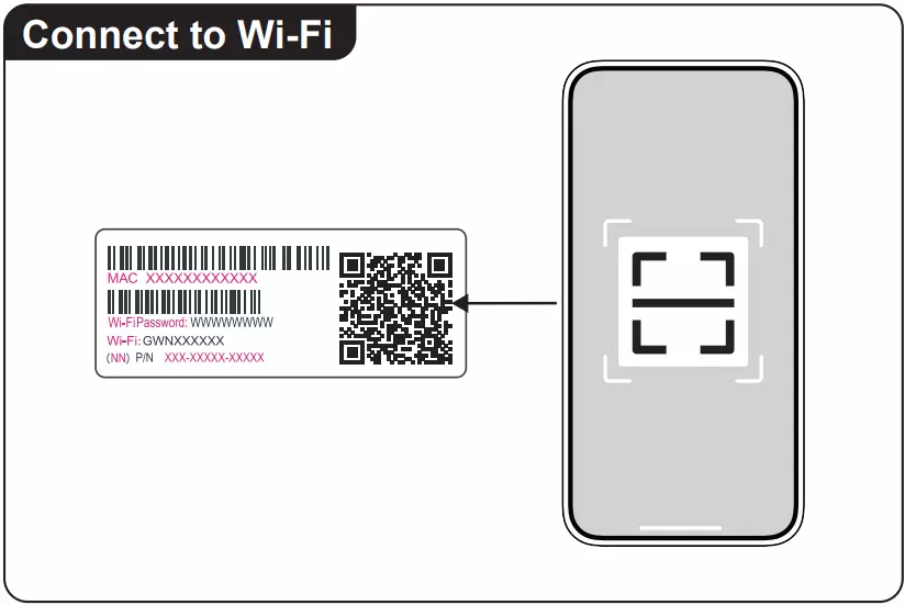
Scan the QR Code
To easily set up, manage your router, and quickly connect to Wi-Fi using your phone, scan the QR code on the device label with the Grandstream Home App.
Steps:
- Download the Grandstream Home App from the App Store or Google Play: Grandstream Home App Guide
- Launch the app and sign in or register.
- Tap the “+” icon to add a new device.
- Scan the QR code located at the bottom of the router.
- Follow the steps provided in the app to complete device setup.
For more details on app features, configuration options, and remote management tools, visit the full guide: Grandstream Home – User Guide
Wall Mounting
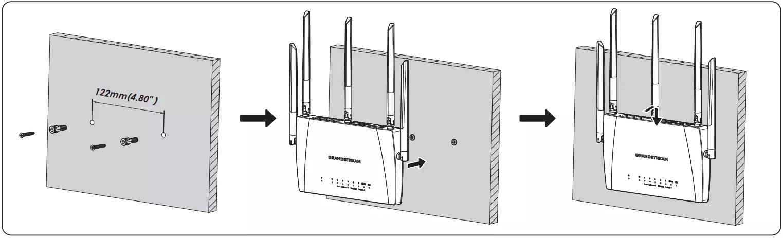
To install the GWN7062M on a wall:
- Select a flat, stable surface suitable for supporting the router.
- Use the wall-mount slots on the back of the unit as a guide to mark the hole positions.
- Drill holes where marked and insert wall anchors if necessary.
- Insert the mounting screws, leaving enough space for the router to slide onto them.
- Hang the router on the screws and gently slide it down until it’s secure.
- Adjust the antennas to the desired position before connecting cables and power.
GETTING STARTED
The routers provide an intuitive web GUI configuration interface for easy management to give users access to all the configurations and options.
This section provides step-by-step instructions on how to read LED indicators and use the Web GUI interface.
LED Indicators
The GWN7062M has 9 LED indicators on the top panel. The first LED, labeled with a power icon, is a multi-color system status indicator. It uses different colors and blinking patterns to show power and overall router status (such as booting, ready, upgrading, or fault). The remaining LEDs are single-color indicators (green on / off) for other functions such as WAN, LAN, USB, and Wi-Fi. The table below describes the colors and behavior of the system status LED only.
System LED Status | Indication |
Off | The router is powered off. |
Solid Blue |
|
Flashing Blue |
|
Flashing Pink |
|
Solid Pink |
|
Flashing Green | Firmware upgrade in progress. |
Solid Green |
|
Flashing Red |
|
Solid Red |
|
Solid Yellow |
|
Flashing Yellow | No Internet connection. |
LED Indicators
Use the WEB GUI
Access the WEB GUI
The router’s embedded Web server responds to HTTPS GET/POST requests. Embedded HTML pages allow users to configure the device through a Web browser such as Microsoft IE, Mozilla Firefox, or Google Chrome.
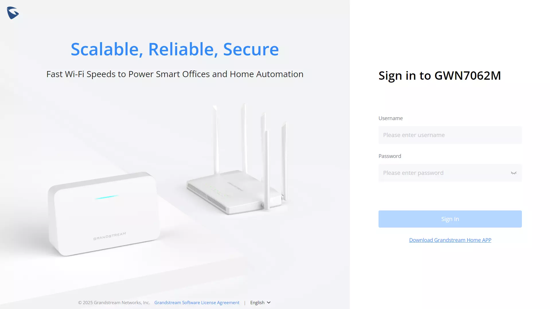
To access the Web GUI:
- Connect a computer to a LAN port of the router.
- Ensure the device is properly powered up.
- Open a Web browser on the computer and enter the web GUI URL in the following format:
https://192.168.80.1 (Default IP address). - Enter the administrator’s login and password to access the Web Configuration Menu. The default administrator’s username is “admin” and the default password is printed on the MAC tag of the unit.

Clicking the “Download Grandstream Home APP” link will open a QR code pop-up.
This QR code redirects users to a download page where they can choose to install the app on:
- Android® via the Google Play Store
- iOS® via the Apple App Store
The Grandstream Home App allows you to remotely monitor, configure, and manage the router directly from your mobile device.
For full setup and management instructions, refer to the official app guide: Grandstream Home App User Guide
At first boot or after a factory reset, users will be asked to change the default administrator and user passwords before accessing the device’s web interface. The password field is case-sensitive with a maximum length of 32 characters. Using strong passwords including letters, digits, and special characters is recommended for security purposes.
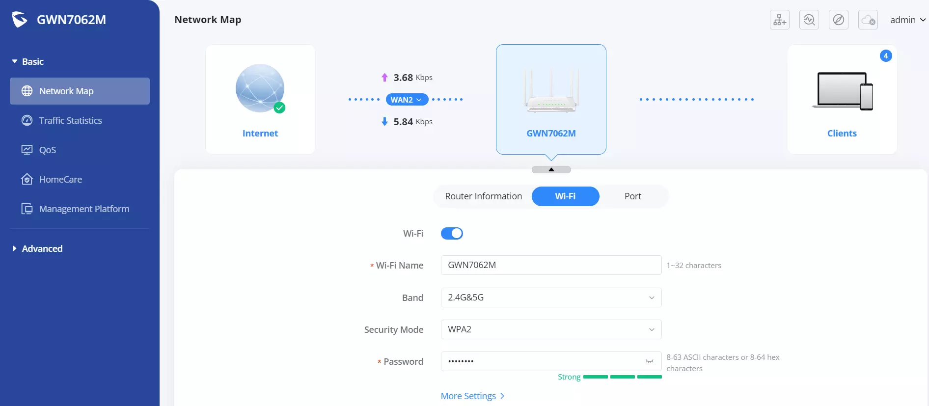
Once the user enters the password, this is the initial page that will be shown. This page contains general information and the status of the router.
Web UI Language
The router web interface supports multiple languages, allowing users to navigate and configure settings in their preferred language.

Steps to Change the Language:
- Locate the Language Menu:
- In the top-right corner of the web interface, click on the admin dropdown menu.
- Select a Language:
- A list of available languages will appear.
- Choose the desired language by clicking on it.
- Apply Changes:
- The interface will refresh automatically and switch to the selected language.
This setting ensures users can interact with the router’s interface in their native or preferred language, improving usability and accessibility.
Rebooting or Logging Out
The Reboot and Logout options are located in the top-right corner of the web interface under the admin menu.
- Reboot: Click on Reboot to restart the router. This will temporarily disconnect all network connections and may take a few minutes to complete.
- Logout: Click on Logout to securely exit the web interface. You will need to log in again to access the settings.

Search
To make it easier for the user to find a particular option quickly, the device’s web UI has a search feature. Users can access this feature by clicking on the search bar at the top of the left-hand menu under Advanced and typing the desired option name.

Quick setup
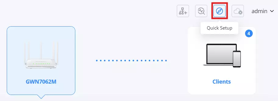
If the user missed the Setup Wizard at the first boot of the device. It’s accessible all the time at the top of the page, and it contains the necessary settings that the user must configure in 4 steps.
- Time Zone
In this step, the user configures the time settings for the device. The Country/Region should be selected from the dropdown menu to ensure accurate localization. The Time Zone will be set automatically based on the selected region, but the user can adjust it manually if needed. Once the appropriate settings are selected, the user should click the Next button (blue arrow) to proceed to the next step.

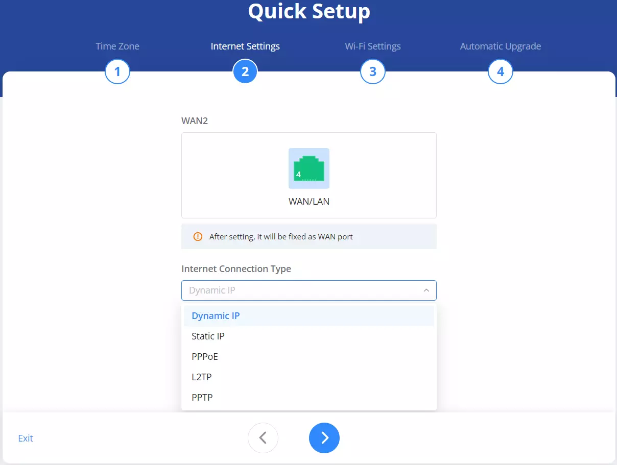
- Internet Settings
In this step, the user selects the appropriate Internet Connection Type to establish network connectivity. The available options include Dynamic IP, Static IP, PPPoE, L2TP, and PPTP. The selection should be based on the user’s internet service provider (ISP) requirements. If unsure, the user should consult their ISP for the correct settings. Once the connection type is chosen, the user should click the Next button (blue arrow) to proceed to the next step.
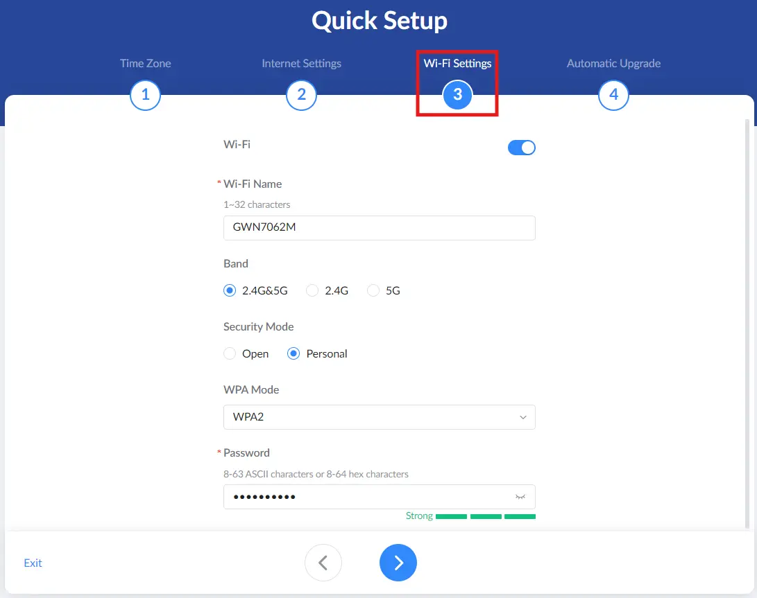
- Wi-Fi Settings
In this step, the user configures the wireless network details for the SSID that will be broadcast by the device.
- Wi-Fi Name (SSID): Enter the wireless network name (1–32 characters).
- Band: Select the operating band: 2.4G&5G, 2.4G, or 5G.
- Security Mode: Choose the security type:
- Open: No password is required.
- Personal: The network is secured and requires WPA settings and a password.
- WPA Mode: (Available when Security Mode is set to Personal) Select the WPA option: WPA/WPA2, WPA2, WPA2/WPA3, or WPA3.
- Password: (Available when Security Mode is set to Personal) Enter the Wi-Fi password. The password can be 8–63 ASCII characters or 8–64 hex characters.
Once the settings are configured, click the Next button (blue arrow) to proceed.
- Automatic Upgrade
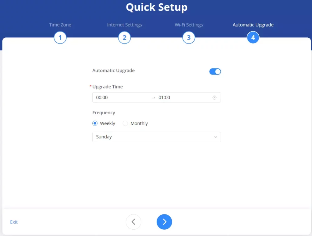
In this step, the user sets up the Automatic Upgrade feature to ensure the device stays updated with the latest firmware. The user can enable or disable automatic upgrades using the toggle switch. If enabled, the Upgrade Time must be specified within a chosen time range. The user also selects the Frequency of updates, either Weekly or Monthly, and specifies the preferred day for the upgrade. Once the settings are configured, the user should click the Next button (blue arrow) to complete the setup.
GDMS Networking – Cloud Management
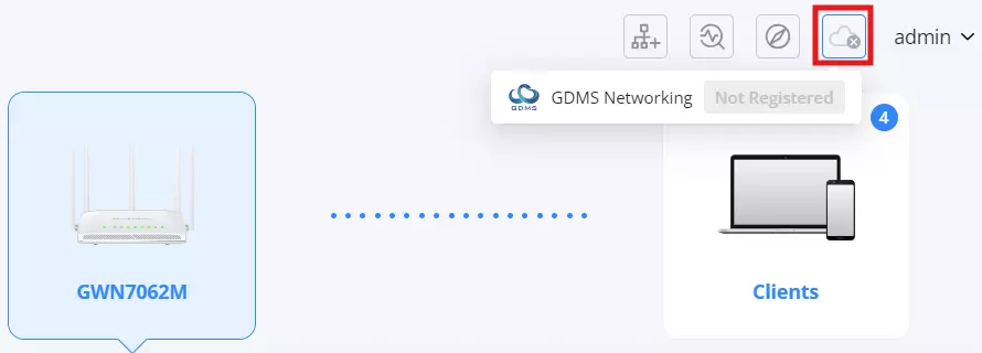
GDMS (Grandstream Device Management System) Networking allows users to register and manage the router remotely via the cloud. Once registered, the router can be monitored and configured from anywhere, providing enhanced flexibility and centralized control.
Benefits of GDMS Networking:
- Remote Management: Configure and monitor the router from anywhere.
- Multi-Device Control: Manage multiple routers under one platform.
- Firmware Updates: Apply updates remotely for enhanced security and performance.
- Real-Time Monitoring: Track network status, connected devices, and traffic analytics.
For more details, visit: GDMS Networking – User Guide
Mesh Network Shortcut
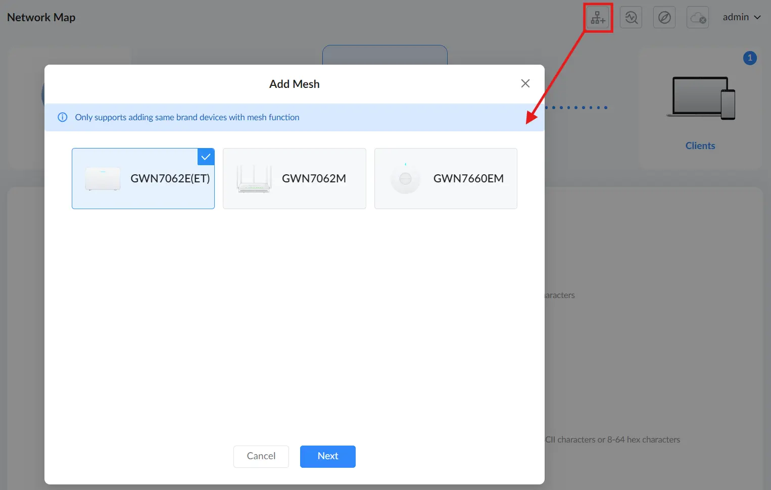
A Mesh Network shortcut is available in the top-right corner of the Network Map page. It provides quick access to the Add Mesh wizard, allowing users to add a new device to an existing Mesh network.
Click the Add New Router shortcut (top-right icon on the Network Map page) to open the Add Mesh wizard.

In the Add Mesh window, select the model of the device you want to add (for example, GWN7062E(ET), GWN7062M, or GWN7660EM), then click Next. After selecting a model, the wizard displays model-specific preparation guidance, including illustrations that show the correct button locations and required steps for that device.
For detailed configuration instructions, refer to the Mesh Section.
BASIC
Basic mode is designed for users who need quick access to essential networking features without the complexity of advanced configurations. This mode includes:
- Network Map: A visual overview of the router’s connection status, current internet speed, and connected clients.
- Traffic Statistics: Real-time monitoring of bandwidth usage across your network.
- QoS (Quality of Service): Tools to prioritize traffic for certain apps or devices, improving network performance.
- HomeCare: Includes Parental Control, SafeSearch, and basic firewall rules for better control and security.
- Management Platform: Offers management through:
- Grandstream Home App (Recommended) – Scan the QR code or click here to learn how to manage your router using the mobile app (available on Android® and iOS®).
- Cloud Access – Optional integration with Grandstream’s cloud platform (GDMS.Cloud) or on-premise (GWN Manager) for extended configuration.
This mode is ideal for home users, remote workers, and small businesses seeking essential network functionality with simple setup and mobile-first control.
Network Map
The Network Map page provides a comprehensive overview of the router’s current status, network connections, and active clients. It dynamically updates based on user interaction, displaying relevant details about the router, connected devices, and network settings.
To navigate to the Network Map:
- Log in to the Web UI of the router.
- In the left menu, click on Basic → Network Map.
This page displays an overview of the router’s network topology, including Internet connection, primary router status, Mesh Nodes, and connected clients.
Collapsible Network Map:
The Network Map includes a collapsible panel feature, allowing users to expand or collapse detailed network information for a cleaner and more efficient interface.
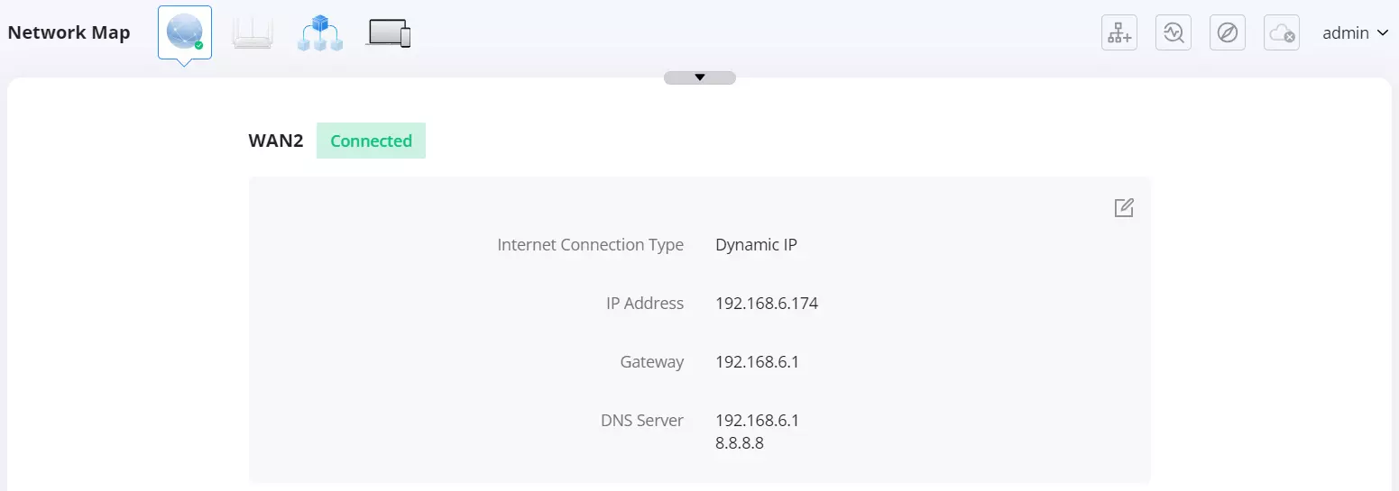
How to Use the Collapse/Expand Feature:
- Expand View:
- By default, the Network Map displays a visual representation of the router’s connections, including Internet, primary router, and clients.
- The detailed WAN connection information is visible below.
- Collapse View:
- Clicking the collapse arrow (▲) at the top of the WAN details panel will hide the connection details, keeping only the high-level network visualization.
- Expand Again:
- Clicking the expand arrow (▼) will restore the full view of WAN details, including IP address, connection type, gateway, and DNS information.
This feature helps users toggle between a detailed and simplified view, making network monitoring more user-friendly and space-efficient.
Internet Connection Details
Clicking on the Internet icon provides a detailed view of the WAN connection status:
- Internet Connection Type (e.g., Dynamic IP, Static IP, PPPoE, L2TP, PPTP).
- IP Address assigned by the ISP or another Router.
- Gateway and DNS Server information.
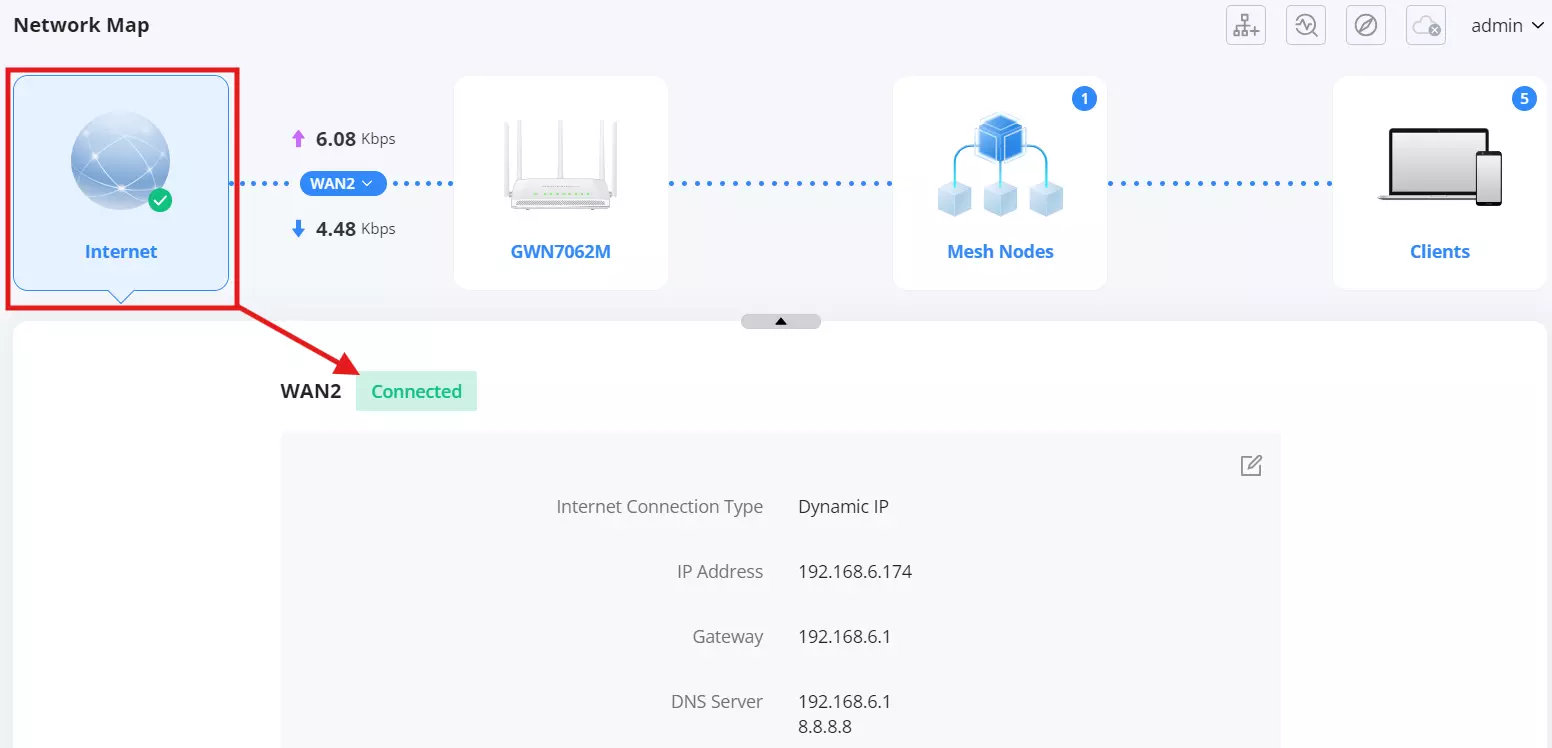
To edit the WAN settings, click on the edit icon next to the Internet details. A pop-up window will allow selecting the connection type and configuring the necessary parameters.
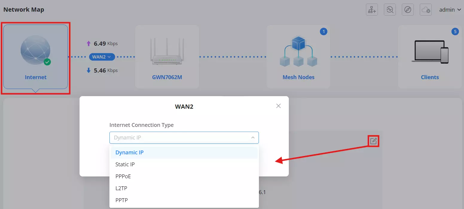
Internet Connection Types:
When configuring the WAN (Internet) connection type, users can select from the following options:
- Dynamic IP – The router automatically obtains an IP address from the ISP. This is the most common setting for residential and many business connections.
- Static IP – Requires manual entry of an IP address, subnet mask, gateway, and DNS servers. Used for fixed-address internet connections.
- PPPoE (Point-to-Point Protocol over Ethernet) – Used for DSL connections where the ISP provides a username and password for authentication.
- L2TP (Layer 2 Tunneling Protocol) – A VPN-based internet connection method that requires an L2TP server address, username, and password.
- PPTP (Point-to-Point Tunneling Protocol) – An older VPN-based internet connection method, similar to L2TP but generally less secure.
Users should select the appropriate connection type based on their ISP’s requirements.
Primary Router Information
Displays essential details about the router, including:
- MAC Address: The unique identifier assigned to the router.
- LAN IPv4 Address: The internal IP address used for local network communication.
- Firmware Version: Indicates the firmware version currently installed.
- Uptime: Shows how long the router has been running since the last restart.
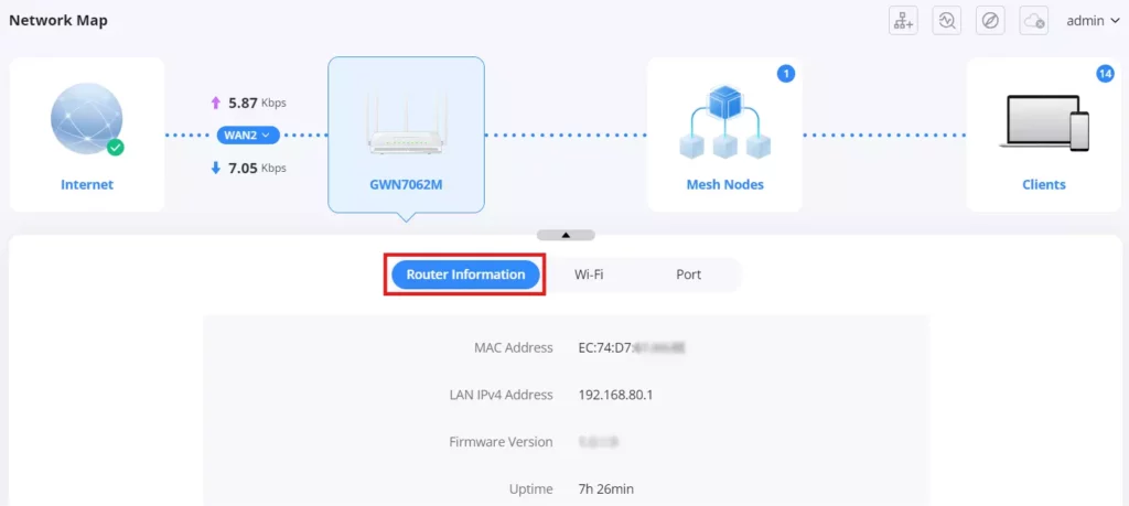
Wi-Fi Setting
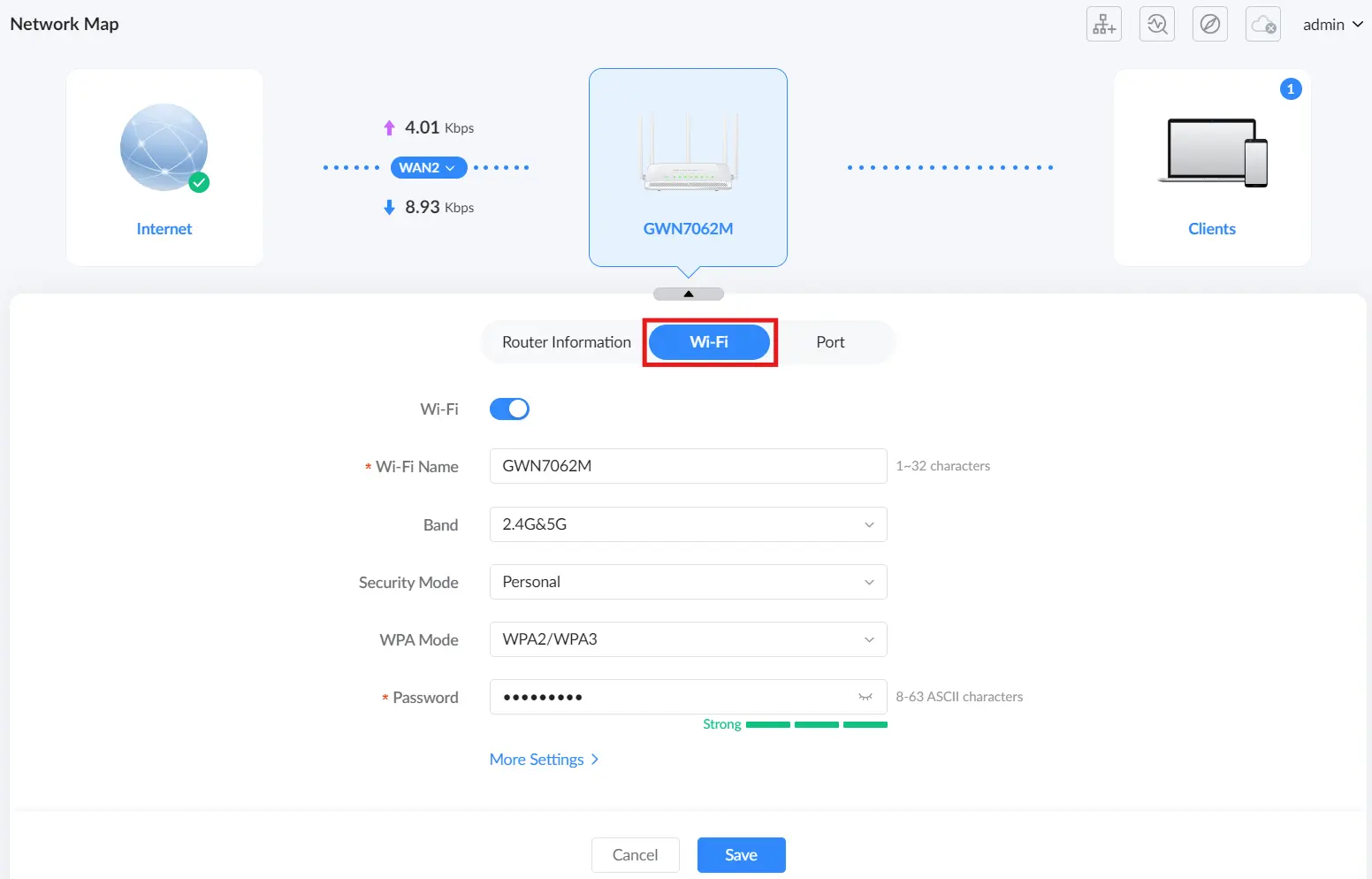
The Wi-Fi tab on the Network Map page allows users to quickly view and modify the main wireless settings, including enabling/disabling Wi-Fi, SSID details, and security options. After making changes, click Save to apply them.
- Wi-Fi: Enable or disable the wireless function. When disabled, the device will operate as a wired router only.
- Wi-Fi Name: Set or modify the SSID (1–32 characters).
- Band: Select the operating band (for example, 2.4G&5G, 2.4G, or 5G, depending on the model and configuration).
- Security Mode: Choose Open (no password) or Personal (secured network).
- WPA Mode: Available when Security Mode is set to Personal. Select the WPA option (for example, WPA/WPA2, WPA2, WPA2/WPA3, or WPA3).
- Password: Available when Security Mode is set to Personal. Enter the Wi-Fi password (8–63 ASCII characters or 8–64 hex characters).
Click More Settings to open Wi-Fi Settings → Wi-Fi, where you can configure additional SSIDs and advanced wireless parameters.
Port Status
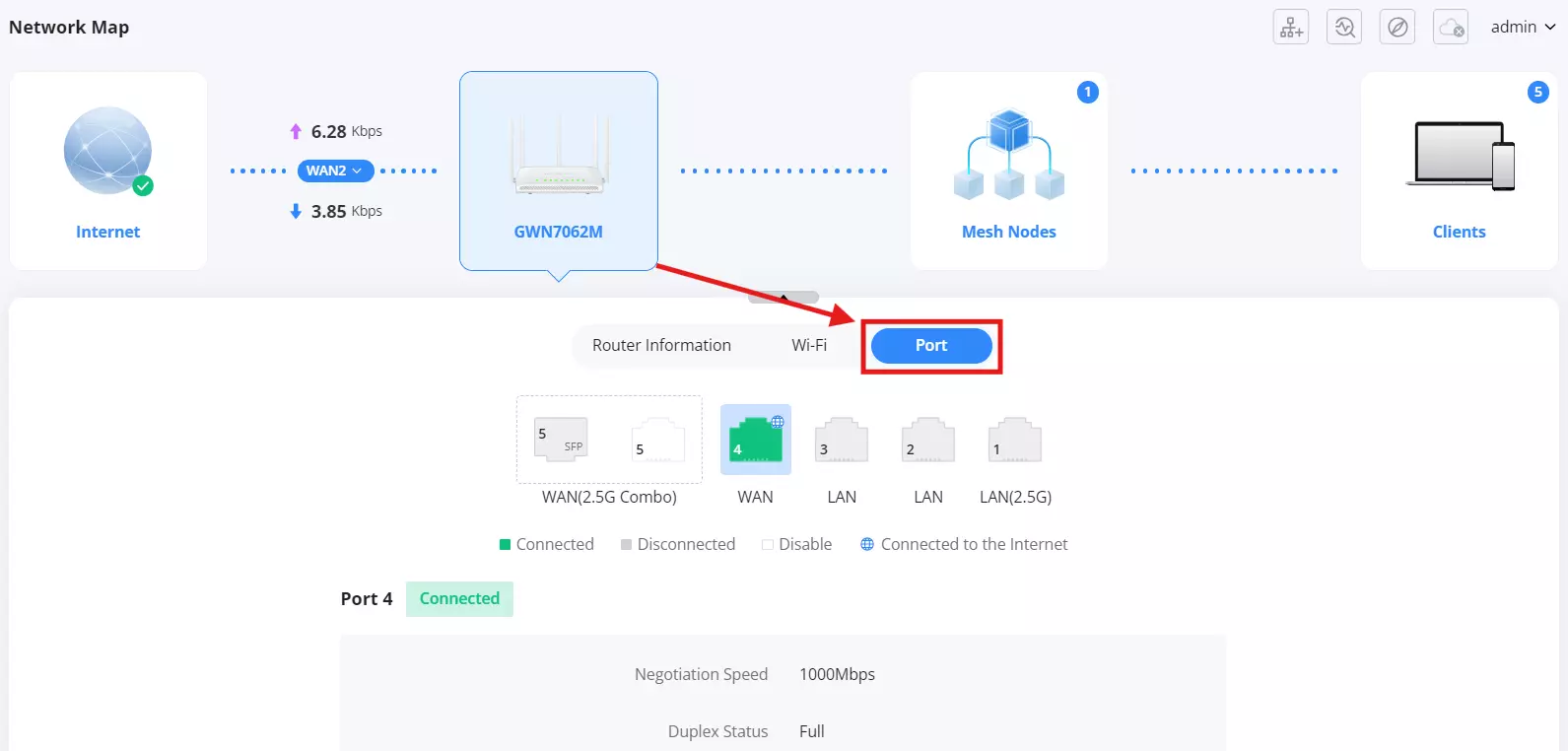
The Port tab in the Network Map shows the real-time physical connection status of each port on the GWN7062M. It helps identify which ports are active, which are linked to the Internet, and which are inactive.
Accessing the Port Status
- Click the router icon (GWN7062M) in the Network Map.
- Select the Port tab to view detailed connection information.
Port Status Indicators
| Status | Meaning |
|---|---|
| Connected | The port has a valid physical connection to another device, and the link is up. This status is used for all ports (WAN and LAN), including the 2.5G Combo WAN port when its selected interface is active. Note: The combo port includes two interfaces: RJ-45 Ethernet and SFP, but only one can be used at a time. When one interface is active, the other automatically becomes Disabled. To change which interface is active, go to Advanced → Internet Settings → Internet Settings, select the desired interface (RJ-45 or SFP), and save the configuration. |
| Disconnected | No cable or module is detected, or the connected device is powered off. |
| Connected to the Internet | The port is acting as the WAN interface and currently has Internet access. |
| Disabled | Applies only to the 2.5G Combo Port (WAN). The combo port includes two interfaces: RJ-45 Ethernet and SFP, but only one can be used at a time. When one interface is active, the other automatically becomes Disabled. To change which interface is active, go to Advanced → Internet Settings → Internet Settings, select the desired interface (RJ-45 or SFP), and save the configuration. |
Additional Port Information
- Negotiation Speed – Displays the current link speed (e.g., 1000 Mbps).
- Duplex Status – Indicates whether the connection is Full or Half Duplex.
Mesh Nodes
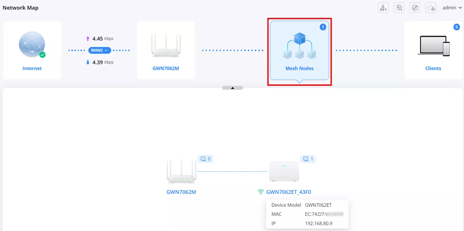
- Displays any Mesh devices connected to the network.
- Shows device type, MAC address, and connection status.
Client Devices
- Lists all devices connected to the router.
- Displays connection type (2.4GHz, 5GHz, or wired).
- Shows IP addresses, real-time bandwidth usage, and connection time.
- Allows basic device management, such as renaming, blocking, or prioritizing clients.

Managing Connected Devices:
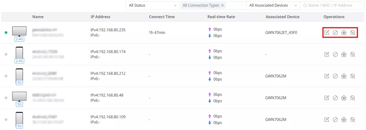
Users can perform various actions directly from the Operations column:
- Edit (Pencil Icon) – Modify the device name or other settings.
- Block (Prohibited Icon) – Restrict network access for the selected device.
- Parental Control (House Icon) – Add the device to the Parental Control list for content filtering and time-based access restrictions. For more details, refer to Basic → HomeCare → Parental Control.
- Repair (Circular Arrow Icon) – If the device has connection issues, clicking this icon redirects the user to Intelligent Detection → Internet Failure for troubleshooting.
Traffic Statistics
The Traffic Statistics page provides real-time insights into network usage, helping users monitor data consumption and optimize bandwidth. This section is divided into two key tabs: Client Statistics and App Statistics, each offering detailed data on network activity.
Client Statistics
This tab displays network usage per device, allowing users to track bandwidth consumption for individual clients.
- Client History Statistics: A graphical representation of data usage over time.
- Top Clients List: Displays the highest bandwidth-consuming devices, showing:
- Device Name & MAC Address
- Total Data Consumption
- Upload & Download Usage
- Filtering & Sorting Options: Users can filter by:
- Specific clients
- Time periods (Today, This Week, This Month)
- Sorting methods (Upload or Download usage)

The Traffic Statistics page includes interactive visual representations of network usage. Users can hover over graphs to view additional details about specific clients or applications.

App Statistics
This tab provides a breakdown of network usage based on application types, enabling better traffic management and prioritization.
- App History Statistics: Tracks total bandwidth usage over time.
- App Group Traffic Statistics: Categorizes network traffic into groups such as:
- Gaming, VoIP, Social Media, Streaming, Official Work, and Others
- App List: Displays detailed statistics for each application, including:
- Total Usage, Upload, Download, and Visit Count
- Percentage of Total Network Traffic
- Filtering Options: Users can filter by:
- Specific application types
- Time periods (Today, This Week, This Month)

It’s also possible on this page to hover over graphs for more details or more info.

QoS (Quality of Service)
Quality of Service (QoS) is a network feature that prioritizes specific types of internet traffic to ensure optimal performance for critical applications. By enabling QoS, users can allocate bandwidth more efficiently, reducing latency for gaming, streaming, video calls, and other high-priority tasks.
Enabling QoS
To enable QoS on the router, navigate to:
Basic → QoS
- Toggle the QoS function switch to Enable.
- Ensure that bandwidth settings are properly configured for QoS to function effectively.

Bandwidth Settings
Users can manually define the maximum upload and download bandwidth for each WAN port to optimize traffic distribution.
- WAN Selection: Displays multiple WAN interfaces (e.g., WAN1, WAN2) to apply QoS settings separately.
- Maximum Upload Bandwidth: Define the highest upload speed per WAN connection (Kbps or Mbps).
- Maximum Download Bandwidth: Set the maximum download speed for each WAN interface.
Proper configuration of these settings ensures that QoS operates efficiently without network congestion.
Priority Surfing Mode
Users can select traffic prioritization modes based on their preferred usage:
- Auto Mode: The router dynamically manages bandwidth based on network activity.
- Game First: Prioritizes gaming traffic to reduce latency and lag.
- Video First: Ensures seamless streaming by prioritizing video traffic.
- Web First: Allocates bandwidth for smooth web browsing and productivity tasks.
Note: After configuring QoS settings, click Save to apply the changes.
This feature is highly beneficial for gamers, remote workers, streamers, and households with multiple users, ensuring a balanced and optimized network experience across different applications.
HomeCare
Parental Control
The Parental Control feature under Basic → HomeCare allows administrators to manage and control internet access for specific devices connected to the network. This feature is particularly useful for parents, schools, or workplaces to enforce internet usage policies.
Key Features of Parental Control:
- Time-Based Restrictions: Set internet access schedules to restrict online usage during specific hours, such as school nights or weekends.
- App & URL Filtering: Block or allow certain applications or websites to ensure safe browsing.
- Device-Specific Rules: Apply different rules for different devices, either by selecting from connected clients or adding devices manually.
- General Settings: Option to block internet access for unmanaged devices that are not subject to parental control rules.
To configure Parental Control, navigate to Basic → HomeCare → Parental Control and use the available options to set restrictions, add devices, or customize browsing rules.
Parental Control
The Parental Control section allows administrators to define how unmanaged devices connect to the internet. This feature ensures that any device not assigned parental control rules is restricted from accessing the network, enhancing security and ensuring controlled internet usage.
To enable Parental Control:
- Navigate to Basic → HomeCare → Parental Control.
- Then toggle on Block Internet for Unmanaged Devices.

Adding a Client to Parental Control
To apply parental control rules to specific devices, users must add them to the Parental Control client list. This allows administrators to set time restrictions, content filters, and other network rules for selected devices.
Navigating to Add a Client:
To add a device under Parental Control:
- Navigate to Basic → HomeCare → Parental Control.
- Click on the Add button at the top-left of the client list.
Once a client is added, administrators can configure various settings such as online time limits, app restrictions, and URL filtering.

Selecting or Manually Adding a Device
After clicking Add in the Parental Control section, users have two options to add a device:
- Select from Clients – Choose a device that is already connected to the router from the available list.
- Add Manually – Enter the MAC address of a device that is not currently connected but needs to be managed under Parental Control.
Important Note:
- Devices with randomized MAC addresses may not be properly controlled. It is recommended to disable MAC randomization on the client device to ensure proper enforcement of rules.
Steps to Add a Device:
- Navigate to Basic → HomeCare → Parental Control.
- Click Add, then choose either:
- Select from Clients to pick a device from the connected list.
- Add Manually to enter the MAC address of an offline device.
- Once added, the device will appear in the list and can be assigned specific Parental Control rules.

Enabling and Configuring Internet Time Limits
The Internet Time Limit feature in Parental Control allows users to define specific time periods when internet access is blocked for selected devices. This is particularly useful for managing children’s online activity by restricting internet usage during school nights or setting time-based limitations.
Steps to Enable Internet Time Limits:
- Navigate to Basic → HomeCare → Parental Control.
- Click Add to add a client device if not already listed.
- Enable Internet Time Limit by toggling the switch.
- Configure the blocked time periods:
- Set restricted hours for school nights (Sunday to Thursday).
- Define blocked times for weekends (Friday and Saturday).
- Enable Time Duration of Internet Use to specify the maximum allowed usage time per day:
- Assign usage limits for school days (Monday to Friday).
- Configure usage limits for weekends (Saturday and Sunday).
- Once configured, click Save to apply the settings.
These restrictions will automatically disconnect the device from the internet during the specified times.

Configuring App and URL Filtering
The App and URL Filtering feature under Parental Control allows users to restrict access to certain applications and websites, ensuring a safer browsing environment.
Steps to Configure App and URL Filtering:
- Navigate to Basic → HomeCare → Parental Control.
- Select a device or add a new device.
- Under the App Allowlist, configure application-based restrictions:
- Use the Block section to restrict specific apps or app categories, such as gaming or social media.
- Use the Allow section to specify permitted applications.
- Under the URL Allowlist, manage website access:
- Use the Block section to restrict access to specific website categories like adult content, phishing, hacking, and gambling.
- Add a custom URL to block a specific website using the URL Blocklist field.
- Click Apply to save the settings.
These settings ensure that only allowed applications and websites are accessible, preventing exposure to inappropriate content.

Applying Parental Control Settings to a New Device
The Parental Control feature allows users to quickly apply an existing device’s settings to a new device, simplifying network management.
Steps to Apply Settings to a New Device:
- Navigate to Basic → HomeCare → Parental Control.
- In the list of configured clients, locate the device with the desired settings.
- Click the “+” icon under the Operations column.
- Select the new client to apply the existing settings.
- Confirm the selection, and the new device will inherit the parental control rules of the original client.
This feature ensures consistency in parental control configurations across multiple devices, streamlining the setup process.

Parental Control – Block Internet and Add Time Options
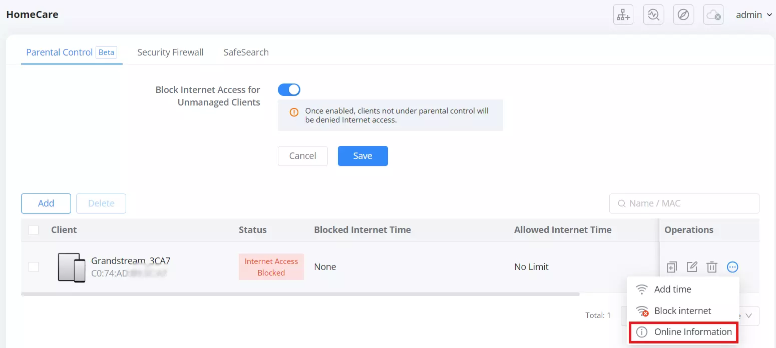
The Parental Control page in HomeCare features enhanced control tools for managing internet access per device. Each connected device appears as a row with control icons represented by three dots ···.
Once you click the dots for any listed client, you can choose between:
- Add Time
Clicking Add Time opens a pop-up that lets you temporarily allow a device to connect to the internet during a defined time slot. This is ideal for managing screen time or temporary access.

Then the user can select a specific internet access duration (15min, 30min, 1h, 2h) from the “Add time” dialog.

2. Block Internet
Clicking Block Internet from the client’s three-dot menu allows you to immediately deny that device access to the internet for the rest of the day.

Once selected, a confirmation pop-up appears to ensure the admin intends to block internet access for the selected client.

After confirmation, the client’s row is visually updated with a red badge showing Internet Access Blocked under the “Status” column.

- Online Information
The Online Information page under Parental Control provides detailed usage statistics for each managed client. Administrators can review internet time, data usage, and application traffic, and optionally block specific apps directly from this page.
Accessing Online Information
- Navigate to Basic → HomeCare → Parental Control.
- In the client list, locate the device you want to inspect.
- Click the three-dot (···) menu under the Operations column.
- Select Online Information.
The Online Information page can be opened whether the client’s status is Online or Internet Access Blocked.
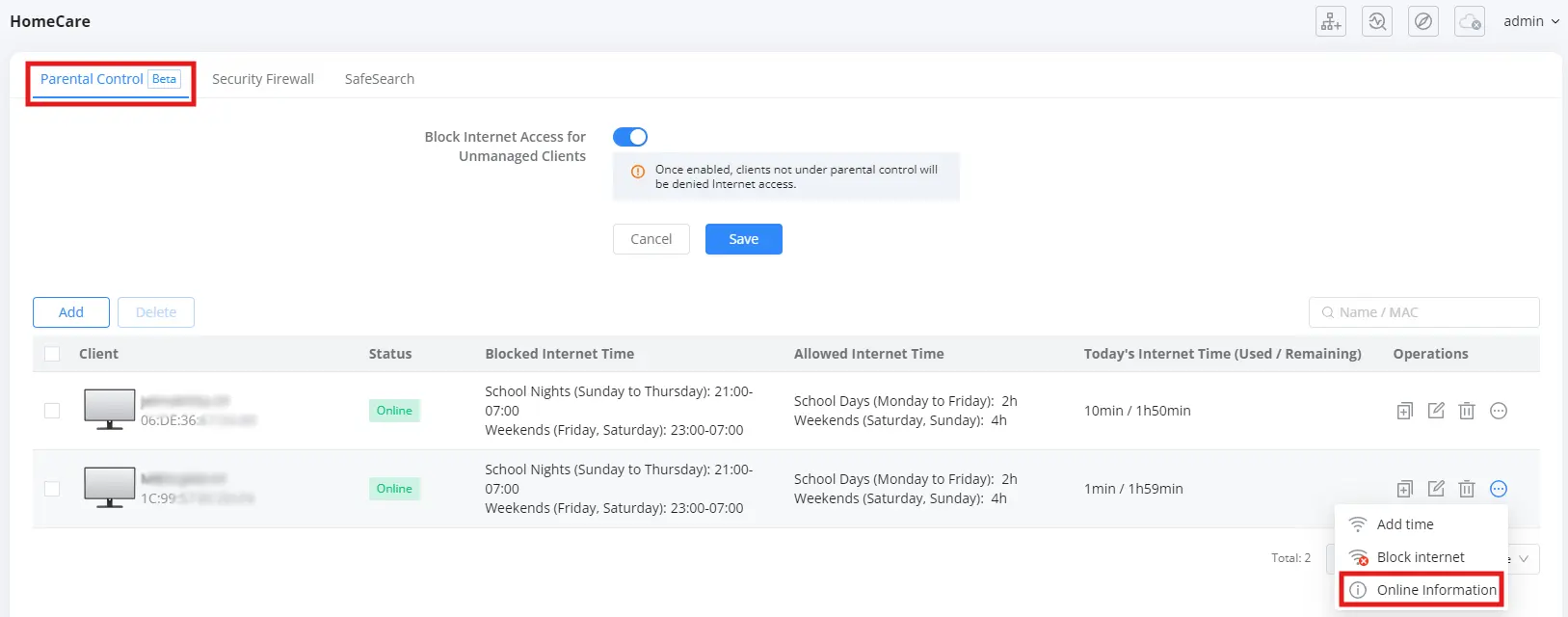
When opened, the page displays a breadcrumb such as:
HomeCare > [Client Name] ([MAC Address]) and provides three time-range tabs:
- Today
- Yesterday
- Last 7 Days
Today / Yesterday – Internet Time & Usage Overview
On the Today and Yesterday tabs, the layout is identical. The page shows how long the client has been online, how much time is remaining (based on Parental Control limits), and when internet access is blocked.
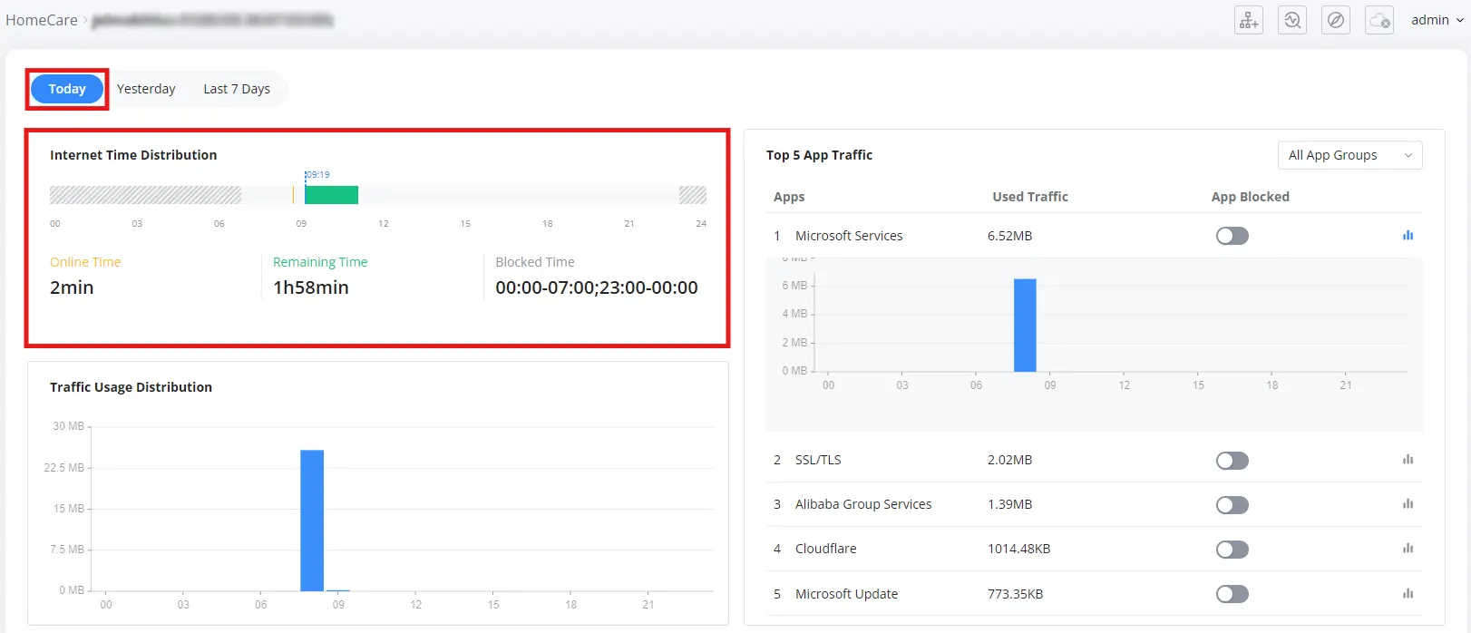
Internet Time Distribution
- Displays a 24-hour bar showing:
- Online Time: total time the client has been connected during the selected day.
- Remaining Time: remaining allowed time for that day, if a daily limit is configured.
- Blocked Time: periods where internet access is blocked by the configured schedule (for example, school nights or bedtime hours).
This helps visualize when the device was online, how much time is still available, and when access is restricted.
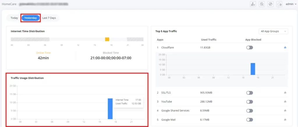
Traffic Usage Distribution
- Shows a chart of data usage over the day for the selected client.
- Each bar represents the amount of traffic used during a specific time period.
- Hovering over a bar displays a tooltip with additional details such as:
- Used Traffic
- Internet Time during that period.
Top 5 App Traffic
- Lists the top five applications or services used by the client for the selected day.
- For each app, the following information is shown:
- App name
- Used Traffic
- App Blocked toggle
- The App Blocked switch can be used to immediately block or allow that application for the selected client.
- An All App Groups drop-down allows filtering by categories such as Gaming, Entertainment, Social, Lifestyle, Work, VoIP, and Study, so administrators can quickly focus on specific types of applications.
Last 7 Days – Aggregated Usage
The Last 7 Days tab shows a summary of the client’s activity over the previous seven days.
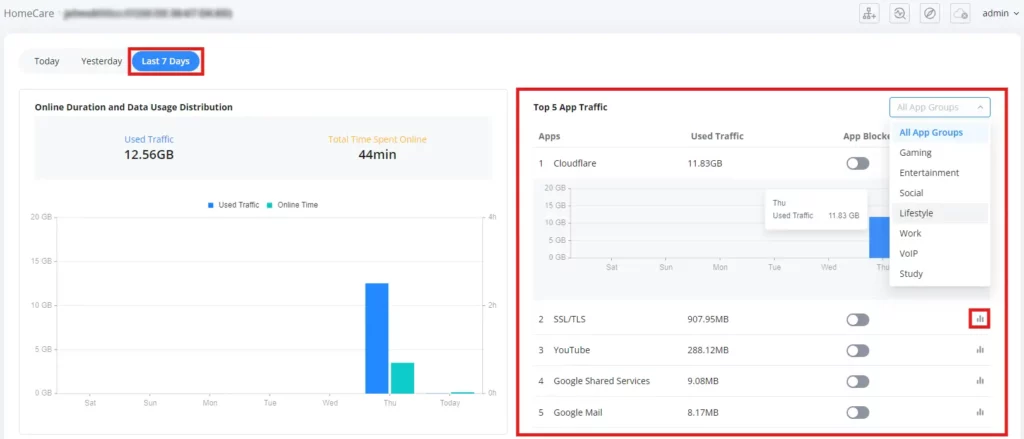
Online Duration and Data Usage Distribution
- Displays the total usage for the selected client across the last seven days, including:
- Used Traffic (cumulative data usage for the period)
- Total Time Spent Online (total online duration over the last 7 days)
- A bar chart below shows daily values, typically indicating:
- Used Traffic per day
- Online Time per day
This view helps administrators quickly identify days with unusually high data consumption or long online periods.
Top 5 App Traffic (Last 7 Days)
- Shows the top applications used by the client during the last seven days, with:
- App name
- Used Traffic over the 7-day period
- App Blocked toggle
- The All App Groups drop-down can again be used to filter applications by category (Gaming, Entertainment, Social, etc.).
- Clicking the three-bar (details) icon next to an application expands additional information about that app’s usage pattern within the selected time range.
- The App Blocked switch allows administrators to block or unblock an application directly from this list, applying the change to the selected client.
Security Firewall
The Security Firewall feature under HomeCare provides basic network security by detecting and blocking potential threats, helping protect connected devices from malicious activity.
To enable Security Firewall, navigate to: Basic → HomeCare → Security Firewall
Enable Basic Security Defense, then click Save to apply the settings. Once enabled, the page displays an activation-time message (for example, “Has been enabled for X Days…”) indicating how long Basic Security Defense has been running.
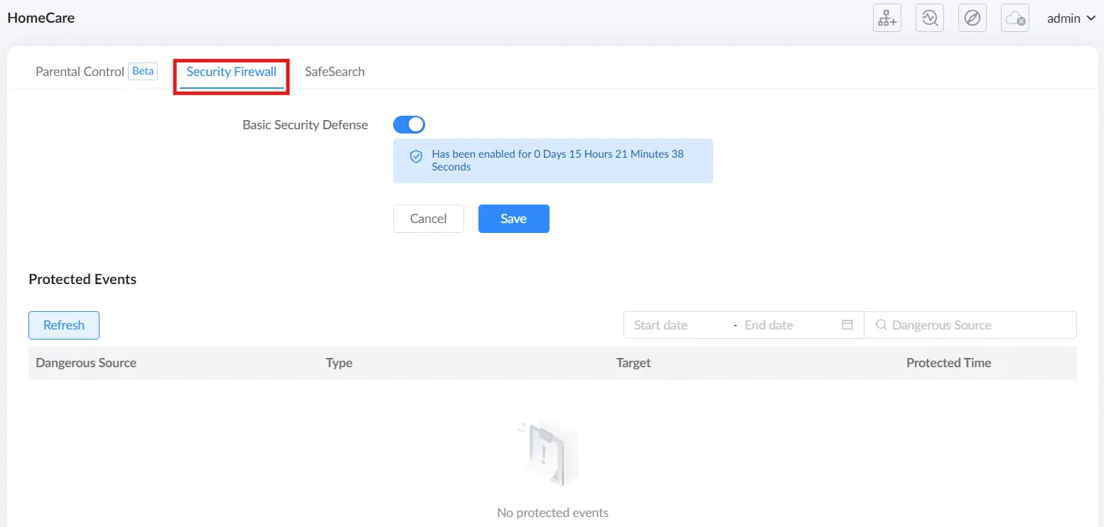
Protected Events
This section logs and displays detected security threats, such as:
- Dangerous Sources: Identifies malicious IP addresses or domains.
- Threat Type: Categorizes security risks based on network activity.
- Target Device: Specifies which device was affected by the blocked threat.
- Protected Time: Logs the date and time of each detected event.
Note: Users can click Refresh to update the event list and monitor real-time security threats.
This feature enhances network protection by proactively identifying and blocking potential cyber threats, ensuring a safer browsing and internet experience for all connected devices.
SafeSearch
The SafeSearch feature is designed to help protect users, especially children, by blocking explicit or sensitive search results across supported search engines.
➤ Accessing SafeSearch
To access this feature:
- Log in to the Web UI.
- Navigate to Basic → HomeCare.
- Click on the SafeSearch tab.

➤ Enabling SafeSearch
You will see a simple toggle switch labeled SafeSearch. When enabled:
- The router will enforce search filters on major search engines.
- This helps restrict access to adult content, inappropriate keywords, and sensitive search results.
After enabling the feature, click Save to apply changes.
Management Platform
Grandstream Home
Grandstream Home is a simplified mobile-based platform designed for easy router control and setup within the local network. It’s ideal for home users and small offices who want fast access to essential features without needing cloud registration or advanced configuration.
Key Features:
- Easy router setup in just a few taps
- Real-time monitoring of internet status and connected devices
- Mesh setup and pairing
- Parental Control
- Wi-Fi settings management
- Local notifications & diagnostics
How to Access:
- Open the router’s Web UI.
- Go to Basic → Management Platform → Grandstream Home.
- Click the “Download APP” link. A QR code will appear. Scan it with your phone to download and install the Grandstream Home App for Android™ or iOS®.


For full usage instructions, please visit the official guide: Grandstream Home User Guide
Cloud
The Cloud section in the routers allows users to remotely manage and monitor their routers using Grandstream’s cloud-based and on-premise management platforms. This feature is particularly useful for businesses, IT administrators, and remote workers who require centralized management and control over their network.

Users can choose between:
- GDMS Networking – A cloud-based platform that allows for centralized remote management.
- GWN Manager – A local, on-premise management solution.
This feature enhances flexibility by offering different deployment options and integration with mobile applications for easy access.
GDMS Networking
The GDMS Networking feature enables remote monitoring and centralized management of GWN devices via the Grandstream Device Management System (GDMS). By adding the router to the GDMS Networking platform, users can remotely configure, manage, and monitor their network from anywhere.

Options Available:
- Go to GDMS: Clicking this button redirects users to the GDMS web portal, where they can sign in and manage their connected GWN devices.
- Download APP: This option provides access to the GDMS mobile application, available for download on both iOS and Android, for on-the-go network monitoring.
This integration allows network administrators to efficiently manage multiple devices remotely while ensuring real-time monitoring and configuration capabilities.
GWN Manager
For users who prefer a local management platform, GWN Manager can be installed and configured.
Installing GWN Manager
- Click Quick Installation Guide to access the online installation manual.
- Follow the setup instructions to install GWN Manager on a local server.
- Click Installed once the setup is complete

Accessing GWN Manager
- After installation, if no GWN Manager service is detected, an error message appears.
- Options available:
- Manager Settings – Configure a local GWN Manager instance.
- Download APP – Install the mobile app for GWN Manager.

Downloading the GWN App
- Clicking Download APP opens a QR Code scanner.
- Users can scan the code to download the GWN App for iOS or Android.

Configuring GWN Manager
Users can connect to GWN Manager manually or automatically:
- Automatic Configuration: Uses DHCP Option 43 to detect and assign the manager’s server.
- Manual Configuration: Users input the Manage Server Address and Port manually.

ADVANCED
Advanced mode unlocks more detailed and sophisticated network settings, suitable for IT professionals and advanced users who require granular control over their network. Key features include:
- Overview: A detailed dashboard of the router’s performance and status.
- Internet Settings: WAN/LAN configurations, DHCP, static IP, and PPPoE settings.
- Wi-Fi Settings: Customization of SSIDs, encryption types, security protocols, and band selection.
- Clients Management: Monitoring and managing connected devices.
- Traffic Management: Advanced QoS, bandwidth control, and traffic shaping.
- NAT & Security: Port forwarding, DMZ, firewall, URL filtering, and DoS protection.
- VPN: Secure remote access with multiple VPN protocols (L2TP, PPTP, OpenVPN, WireGuard, IPSec).
- IPv6 Support: Configuration options for the next-generation Internet Protocol.
- Captive Portal: Guest network setup and authentication.
- System & Maintenance: Firmware upgrades, logs, backup configurations, and Working Mode selection.
This mode is recommended for network administrators, power users, and businesses needing fine-tuned security, performance, and network segmentation.
By switching between these modes, users can balance ease of use with advanced functionality, ensuring an optimized experience for both novice and expert users.
Overview
The Overview Page provides a real-time snapshot of the router’s status, connected devices, and network performance. This page is dynamic, meaning users can interact with different sections for detailed insights and navigation to other settings.
Interactive & Navigation Features
- Clicking on Router, Mesh Nodes, or Client Devices leads to their respective configuration pages.
- Hovering over graphs provides more detailed network activity.
- Statistics can be toggled between Today, This Week, or This Month to analyze trends over time.
This page serves as the primary dashboard for monitoring and managing network activity efficiently.
Key Features of the Overview Page
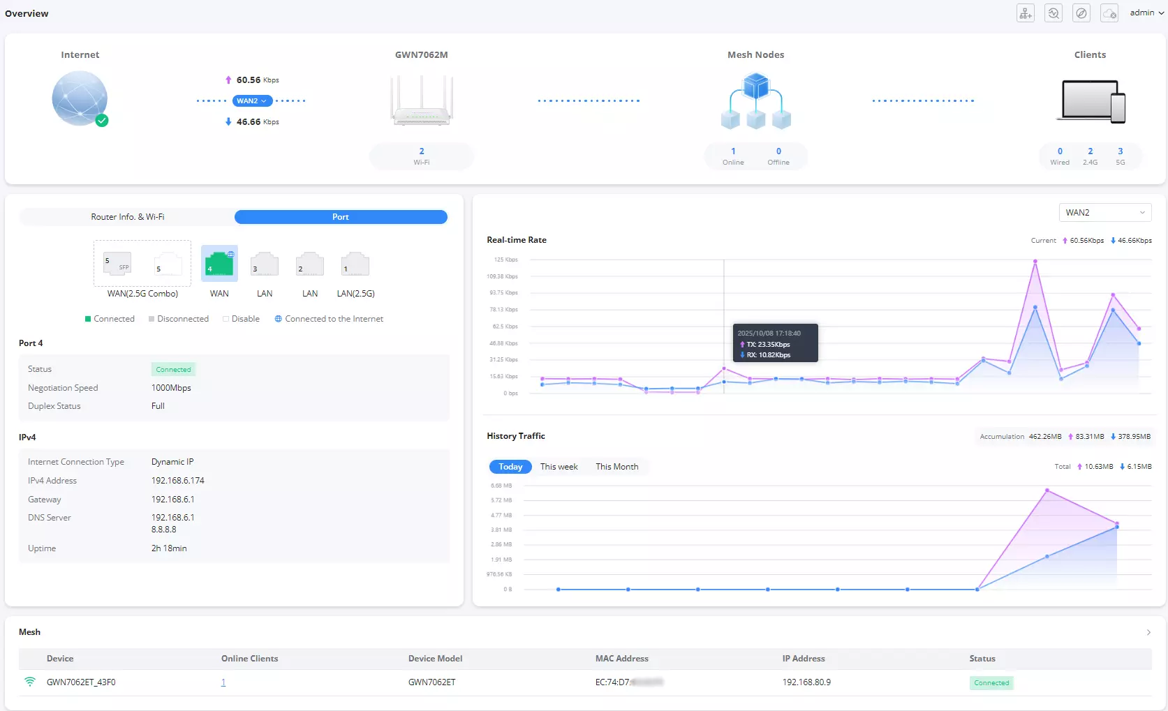
- Network Status:
- Displays the current upload and download speeds.
- Clicking on the router icon navigates to the Wi-Fi settings page.
- Clicking on the Mesh Nodes section directs users to the Mesh Page.
- Clicking on the Client Devices (laptop and phone icons) leads to the Clients Page.
- Router Information & Wi-Fi:
- Users can switch between Port and Wi-Fi views.
- Shows the status of different ports, including Combo ports, WAN, LAN, and USB.
- Displays WAN status, including:
- Connection status (e.g., Connected).
- Negotiation speed.
- Duplex status.
- IP & DNS Information:
- Displays IPv4 Address, Gateway, DNS Server, and Uptime.
- Real-time Rate Graph:
- Shows current network activity in an interactive graph.
- Hovering over the graph reveals precise details of upload and download speeds at specific times.
- History Traffic Graph:
- Users can filter data by Today, This Week, or This Month.
- Displays total data usage with upload and download statistics.

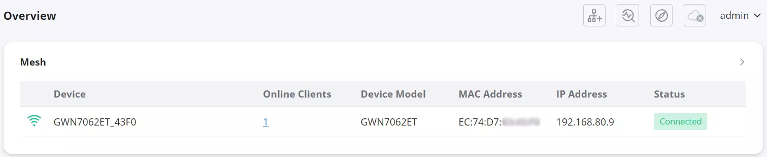
- Mesh Network Section:
- Shows paired mesh devices.
- Clicking on the diagnostic icon next to a mesh device directs users to the Intelligent Detection → Mesh Node Connection settings.
- Clicking on the arrow icon leads to the Mesh Page.

- Client & Wi-Fi Statistics:
- Displays top clients based on data usage.
- Allows users to sort by upload, download, or total usage.
- Shows Wi-Fi usage statistics, including:
- Number of visits per Wi-Fi network.
- Upload and download data usage.
- App Group Traffic Statistics:
- Displays percentage usage of different app categories.
- App Traffic Statistics:
- Shows a detailed breakdown of app traffic, such as Microsoft Services, SSL/TLS, etc.
- Hovering over app sections reveals additional details about upload/download usage.
System Info
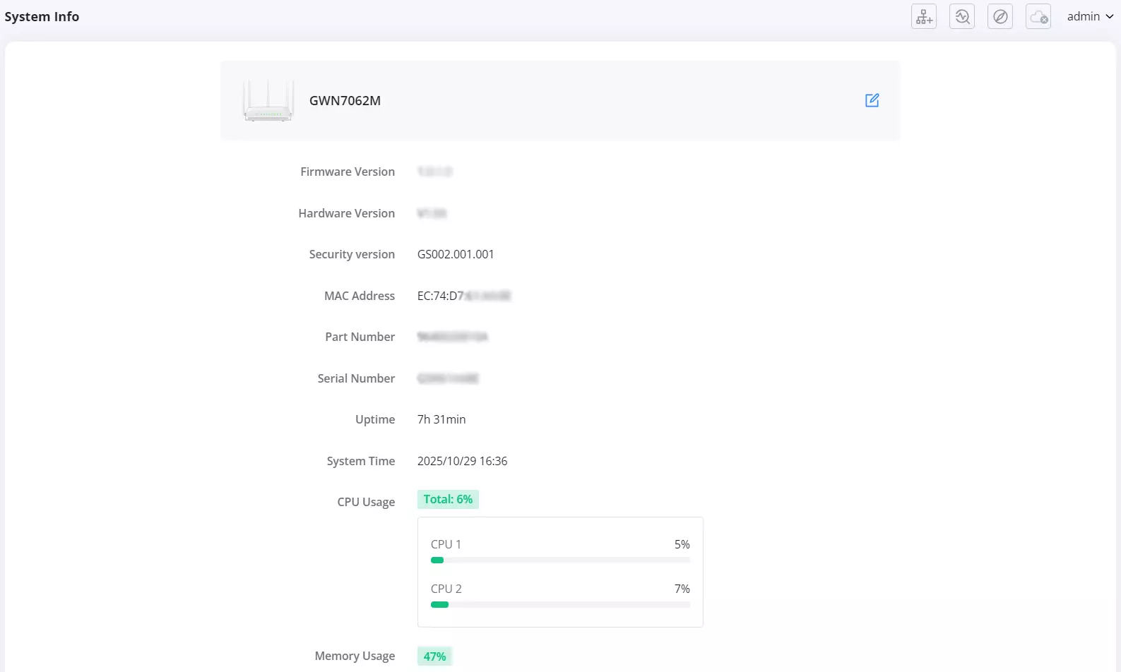
The following details are displayed on this page:
- Device Model: Identifies the router model, e.g., GWN7062M.
- Firmware Version: Displays the installed firmware version.
- Hardware Version: Indicates the router’s hardware revision.
- Security Version: Displays the current security patch level included in the installed firmware. This helps verify if the router has the latest security updates and fixes.
- MAC Address: The unique network identifier assigned to the router.
- Part Number: Manufacturer’s part number for the device.
- Serial Number: A unique identifier for tracking the device.
- Uptime: Displays the total time the router has been running since the last reboot.
- System Time: Shows the current time configured on the router.
Resource Monitoring
The System Info page also provides real-time monitoring of CPU and memory usage:
- CPU Usage:
- Displays the total CPU utilization.
- Shows individual core usage (e.g., CPU 1 and CPU 2).
- Memory Usage:
- Displays the percentage of RAM utilization.
Use Case
This page is useful for:
- Monitoring system performance to check for resource bottlenecks.
- Diagnosing issues related to high CPU or memory usage.
- Tracking uptime to determine router stability.
Internet Settings
Internet Setting
The Internet Settings page (Advanced → Internet Settings → Internet Settings) is used to configure the router’s WAN uplinks. The top of the page provides separate tabs for WAN1, WAN2, and (when available) USB WAN, so each uplink can be configured independently.
Port roles overview
| Interface / Port | Label in UI | Purpose | Notes |
|---|---|---|---|
| Port 5 (2.5G Combo) | WAN1 | Primary WAN uplink | Supports RJ45 Ethernet and SFP (only one can be active at a time). |
| Port 4 (Adaptive) | WAN2 | Secondary WAN uplink (optional) | Functions as LAN by default. When WAN2 is enabled, Port 4 switches to WAN. Removing WAN2 restores Port 4 back to LAN. |
| USB Modem/Dongle | USB WAN | USB-based WAN uplink | Only appears when a supported USB modem is detected. |
WAN1 (Port 5 – 2.5G Combo)
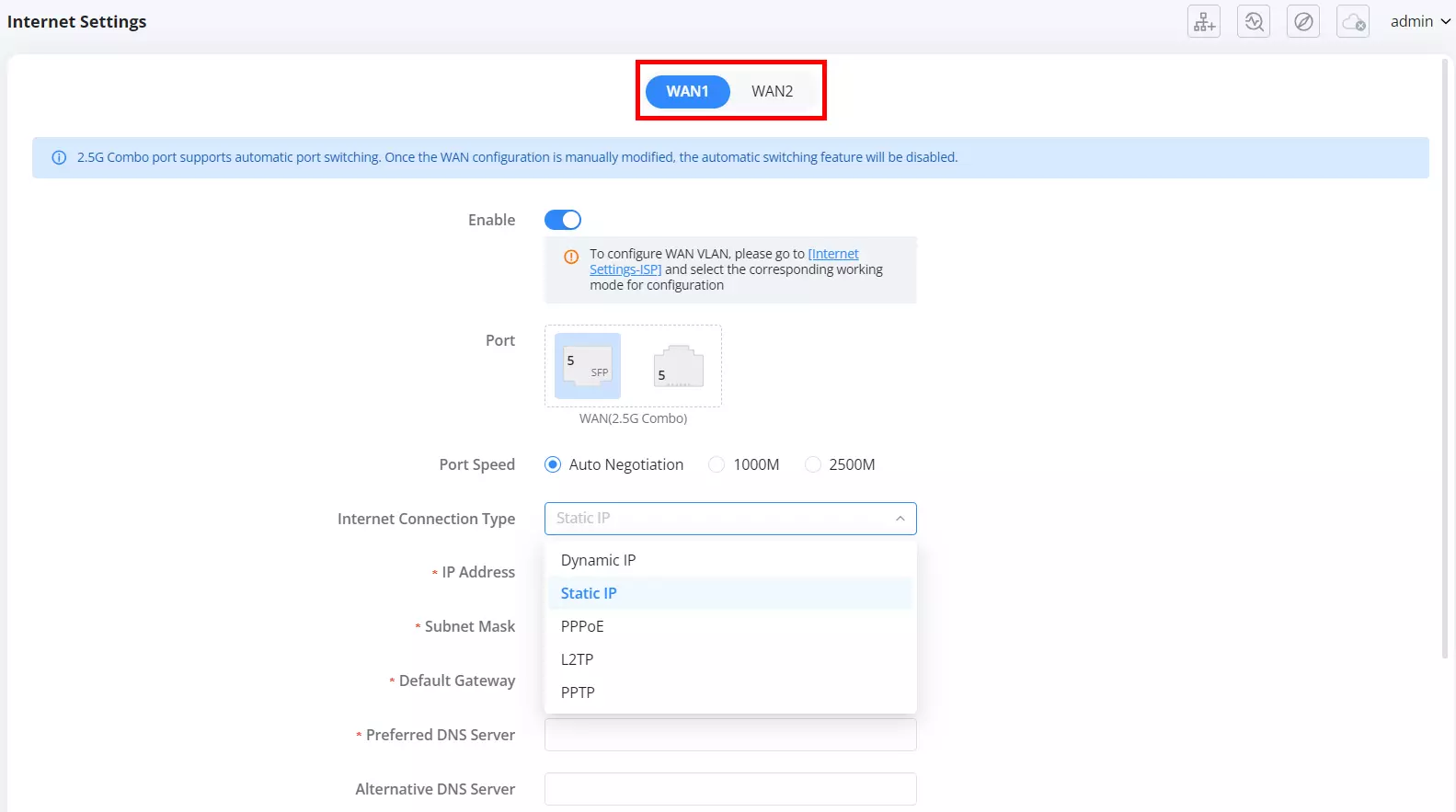
WAN1 configures the dedicated 2.5G Combo WAN port, where you choose the active interface (Ethernet or SFP), set the port speed, and select the ISP connection type.
WAN1 fields
| Field | Description |
|---|---|
| Enable | Enables or disables WAN1 connectivity. |
| Port | Selects the active interface on the 2.5G Combo port (Ethernet or SFP). Only one interface can be active at a time. |
| Port Speed | Sets the WAN1 link speed (Auto Negotiation, 1000M, 2500M). |
| Internet Connection Type | Selects how the router connects to the ISP. Common options include: Dynamic IP, Static IP, PPPoE, L2TP, PPTP. (The page will display the relevant input fields based on the selected type.) |
| Static DNS | Selects how the router connects to the ISP. Common options include: Dynamic IP, Static IP, PPPoE, L2TP, and PPTP. (The page will display the relevant input fields based on the selected type.) |
| Preferred DNS Server / Alternative DNS Server | Manually sets DNS servers (visible when Static DNS is enabled). |
| Save / Cancel | Saves changes or discards edits. |
WAN1 note (automatic switching)
A banner may indicate that the 2.5G Combo port supports automatic port switching, and that manual WAN configuration changes can disable automatic switching. If disabled, it may require a factory reset to re-enable (as stated in the UI banner).
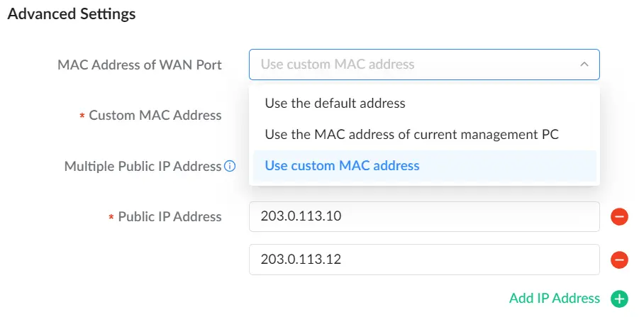
| Field | Description |
|---|---|
| MAC Address of WAN Port | Multiple Public IP Addresses |
| Custom MAC Address | Appears when “Use custom MAC address” is selected. Enter the required MAC value. |
| Multiple Public IP Address | Enables assigning more than one public IP (only use if your ISP provides multiple public IPs). |
| Public IP Address list | Allows entering one or more public IPs. Use Add IP Address to add additional entries and the delete icon to remove one. |
WAN2 (Port 4 – Adaptive WAN/LAN)
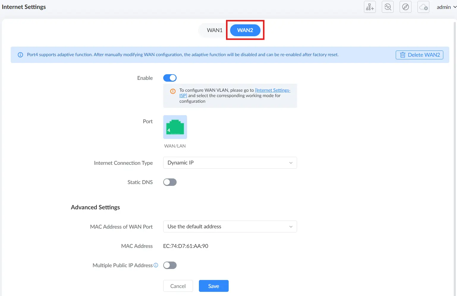
WAN2 configures Port 4, which is an adaptive WAN/LAN port. When WAN2 is enabled, Port 4 operates as a WAN uplink; if WAN2 is removed, Port 4 returns to LAN mode.
WAN2 fields
| Field | Description |
|---|---|
| Enable | Enables or disables WAN2 on Port 4. |
| Delete WAN2 | Removes WAN2 configuration and returns Port 4 to LAN operation. |
| Port | Displays the active port assignment (Port 4 shown as WAN/LAN). |
| Internet Connection Type | Selects the ISP connection type for WAN2 (for example Dynamic IP, Static IP, PPPoE, etc., depending on firmware/UI). |
| Static DNS | Enables manual DNS configuration for WAN2. |
| Advanced Settings | Provides the same type of options as WAN1 Advanced Settings (MAC behavior, multiple public IPs), when supported/visible. |
| Save / Cancel | Saves changes or discards edits. |
WAN2 notes:
- A banner may indicate that Port 4 supports adaptive functionality, and that manual WAN configuration changes can disable the adaptive function until a factory reset (as stated in the UI banner).
- If the page displays a hint about WAN VLAN, follow the UI guidance and configure it under Internet Settings – ISP.
USB WAN
The USB WAN tab is used to configure a USB modem/dongle uplink. This tab is not visible unless the router detects a supported USB modem.
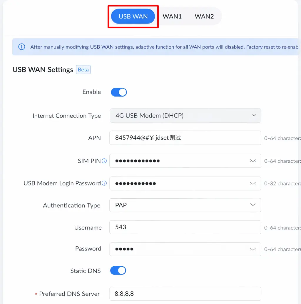
USB WAN fields
| Field | Description |
|---|---|
| Enable | Enables or disables the USB WAN uplink. |
| Internet Connection Type | Selects the USB WAN connection mode (example shown: 4G USB Modem (DHCP)). Available options may vary depending on the modem and firmware. |
| APN | Sets the cellular APN provided by the carrier. |
| SIM PIN | PIN code for the SIM card (required only if the SIM is PIN-locked). |
| USB Modem Login Password | Credentials required by some USB modems/carriers (if applicable). |
| Authentication Type | Authentication method used by the carrier/modem (example shown: PAP). |
| Username / Password | Carrier/modem credentials (if required). |
| Static DNS | Enables manual DNS configuration. |
| Preferred DNS Server | DNS server to use when Static DNS is enabled. |
| Save / Cancel | Saves changes or discards edits. |
USB WAN note (adaptive behavior impact)
A banner may warn that manually modifying USB WAN settings can disable adaptive functions for WAN ports, and that a factory reset may be required to re-enable them (follow the exact wording shown in the UI banner).
LAN Settings
The LAN Settings page under Advanced → LAN Settings allows users to manage the local area network configuration of the GWN7062M. This includes defining VLAN interfaces, assigning VLANs to LAN ports, and binding specific IP addresses to devices on the network.
From this section, users can:
- Create and manage LAN VLANs, including IP addressing and DHCP configuration.
- Assign VLAN IDs and tagging behavior to physical ports under VLAN Port Settings.
- Reserve or bind IP addresses to specific client MAC addresses using Address Binding.
These settings apply to all LAN-designated ports (Ports 1–3, or Port 4 when not used as WAN2) and help segment and control internal network traffic efficiently.
VLAN
The VLAN tab lists all LAN VLAN interfaces and lets you add or modify VLANs used on the LAN side of the GWN7062M.
- Add creates a new LAN VLAN.
- Delete removes selected VLANs (the default VLAN cannot be deleted).
- Columns: VLAN ID, VLAN Name, IPv4 Address, DHCP Server, Address Pool, Operations.
Limits
- Up to 16 VLANs total (including the default VLAN).
- VLAN 1 (Default) is built-in. It cannot be deleted and can only be edited.
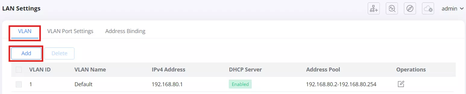
Click Add to open the VLAN form.

- VLAN ID
- Numeric ID for the VLAN. Valid per 802.1Q (2–4094).
- Subject to the device limit of 16 VLANs total.
- VLAN Name: Optional label, 0–64 characters.
- Enable: Turns this VLAN interface on or off.
- Forwarding Destination Group: Select one or more destination groups that this VLAN can use for traffic forwarding (for example, WAN1 (WAN), WAN2 (WAN), VPN interfaces, or other VLAN groups). If All is selected, all existing interfaces are included, and any new interfaces created later will be automatically added to the group.
- IPv4 Address: Router’s address on this VLAN (gateway IP).
- Subnet Mask: Netmask for the VLAN.
- DHCP Server
- When enabled, the router serves IPs to clients on this VLAN.
- Address Pool: start and end IP within the VLAN subnet.
- Release Time (m): DHCP lease time in minutes (range 60–2880).
- Default Gateway: Gateway for clients if different from the VLAN IP (optional; typically the VLAN IP).
- Preferred DNS Server / Alternative DNS Server: Optional DNS servers handed out by DHCP.
- IPv4 Routed Subnet
- When enabled, clients in this VLAN can use public/real IP addresses delivered by the ISP through routing instead of NAT.
- Interface: choose WAN1 or WAN2 as the upstream for the routed subnet.
Save to create the VLAN. The new VLAN appears in the list and can then be assigned to ports in LAN Settings → VLAN Port Settings.
Notes:
- VLAN settings apply to LAN-designated ports (Ports 1–3, and Port 4 only when it is not configured as WAN2).
- Deleting a VLAN removes its DHCP scope and addressing; clients on that VLAN will lose connectivity until reconfigured.
VLAN Port Settings
The VLAN Port Settings tab allows users to assign VLANs to the physical LAN ports of the GWN7062M. Each port can be configured with one PVID (Port VLAN ID) and multiple Allowed VLANs.
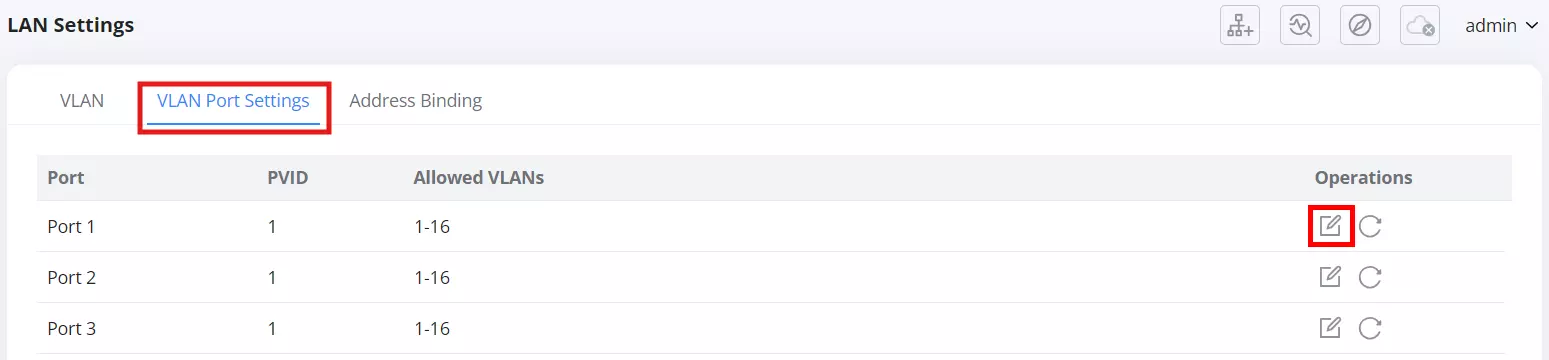
Editing Port VLAN Settings
Click the Edit icon under the Operations column to modify a port’s VLAN configuration.
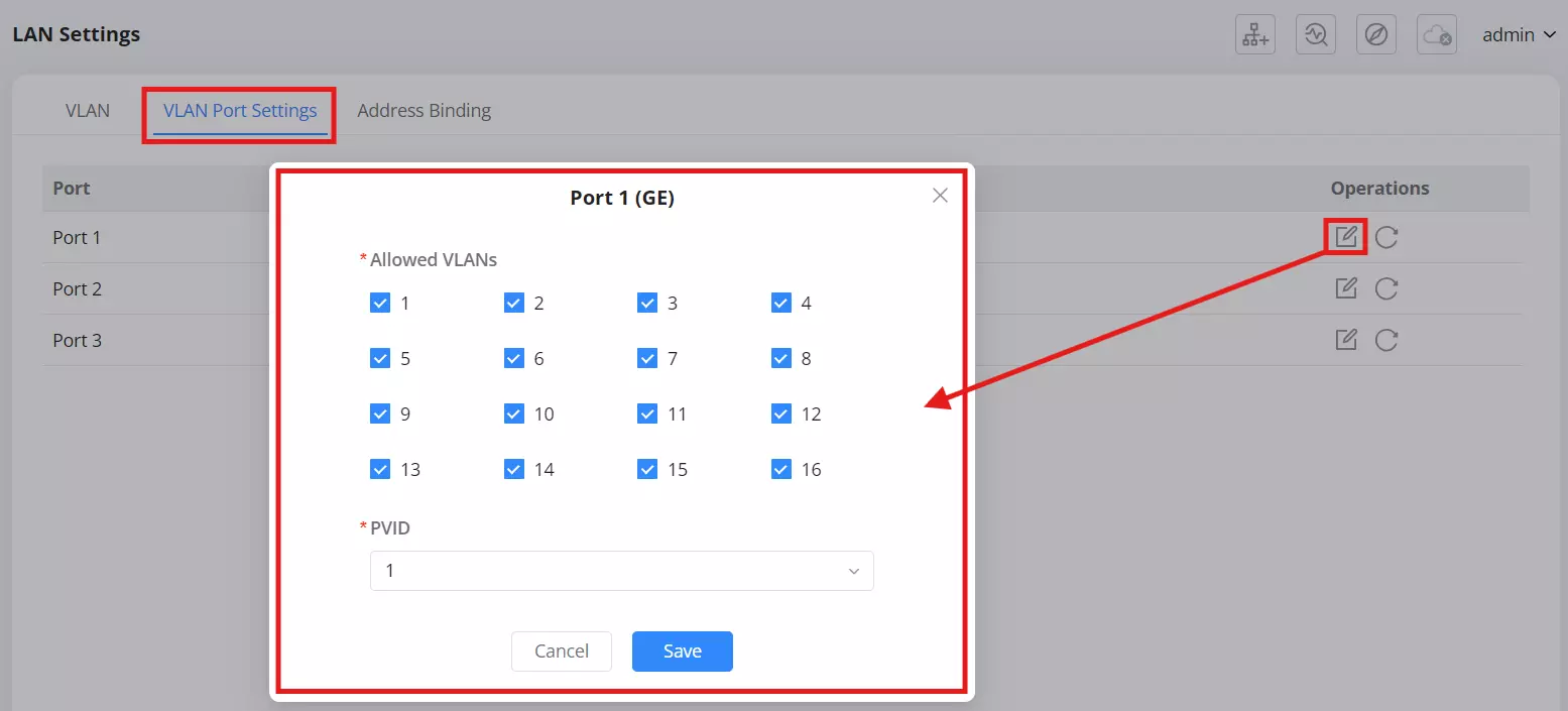
Available Options:
- Allowed VLANs – Select which VLANs are permitted to transmit traffic through this port.
- Multiple VLANs can be checked at once (a maximum of 16 VLANs).
- VLAN IDs available here correspond to VLANs created in the VLAN tab.
- PVID (Port VLAN ID) – Defines the default VLAN ID for untagged packets entering this port.
- Only one VLAN ID can be assigned as the PVID.
- Tagged traffic uses its existing VLAN ID, while untagged traffic is assigned the PVID automatically.
After selecting the VLANs and PVID, click Save to apply the configuration.
Notes
- Only LAN-designated ports (Ports 1–3, or Port 4 when not used as WAN2) appear here.
- The PVID must correspond to one of the VLANs in the Allowed VLANs list.
- Changing VLAN assignments may temporarily interrupt client connections on the modified ports.
Address Binding
The Address Binding tab allows users to assign a fixed IP address to a specific device (MAC address) within the LAN. This ensures that a device always receives the same IP address from the DHCP server.
Click Add to create a new address binding.
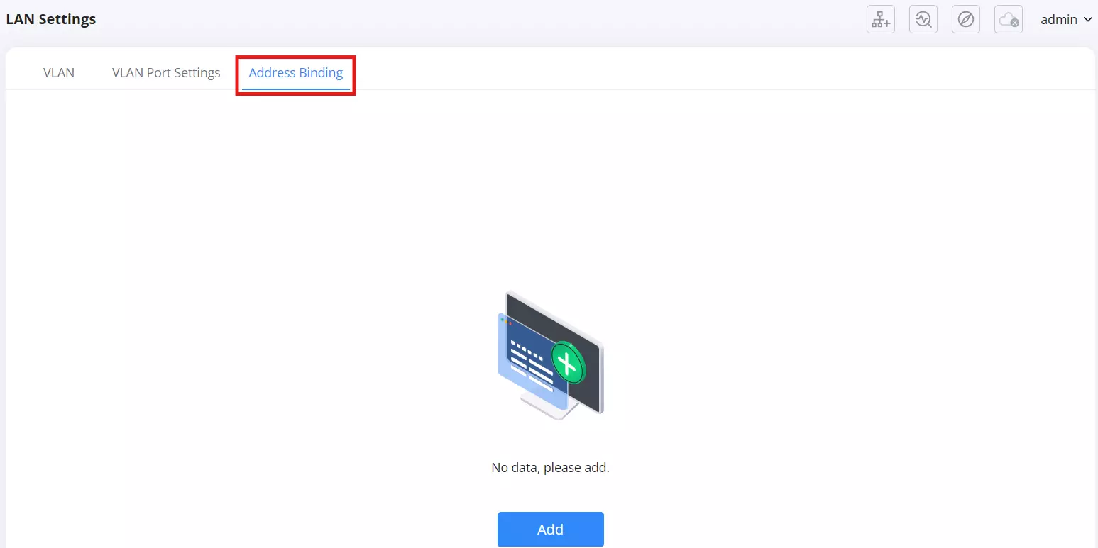
Adding an Address Binding
Generation Mode:
- Add Manually – Enter the device’s MAC Address and the desired IP Address manually.
- Select from Clients – Choose a device from the list of currently connected clients (wired or wireless). The MAC address is filled in automatically.
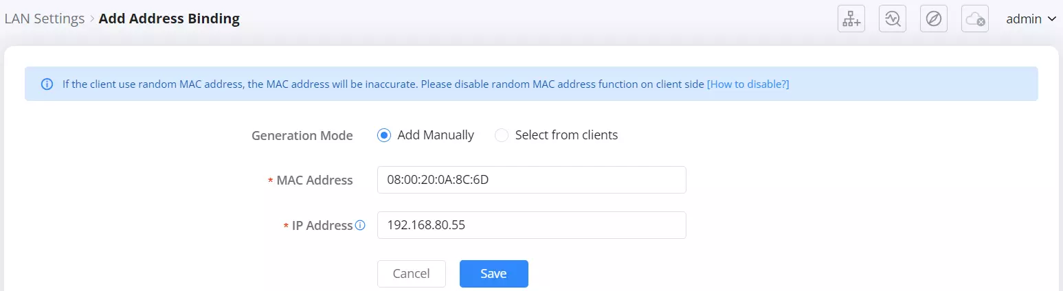
- MAC Address – The unique hardware address of the client device.
- IP Address – The static IP address to assign to this device. Note: The IP address must be within the subnet range of the VLAN to which the device belongs. Otherwise, the binding will not take effect
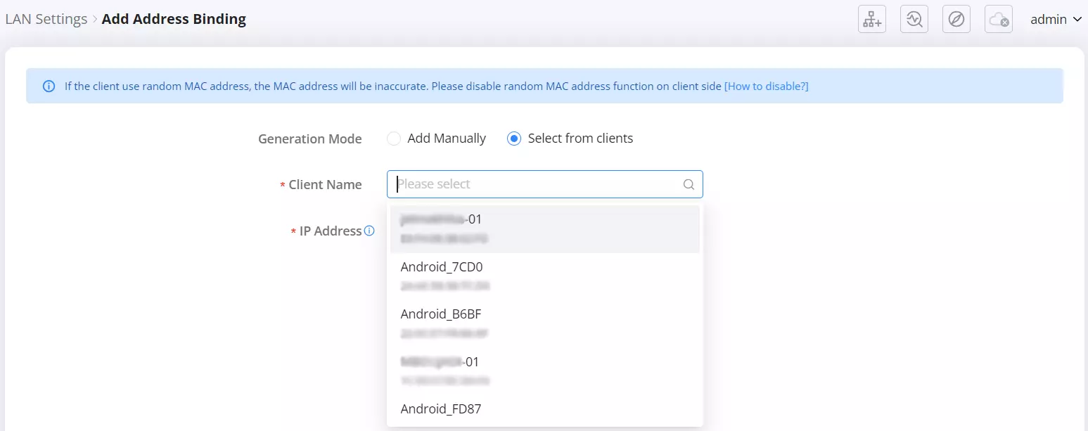
After entering the required details, click Save to apply the configuration.
Important Notes
- If a client uses a random MAC address (as is common on some mobile devices), the MAC address displayed may be inaccurate.
To ensure proper binding, disable the random MAC feature on the client device. - Bound IP addresses will not be dynamically reassigned by DHCP to other clients.
- Address bindings can be viewed, modified, or deleted from this tab as needed.
ISP
The ISP section allows users to configure dedicated Internet Service Provider settings for various services such as IPTV, VoIP, and Internet. It provides flexible VLAN and port-based configuration options to ensure reliable traffic segmentation and optimized performance. On the GWN7062M, both WAN1 and WAN2 can be configured independently, allowing different VLAN or service assignments per interface.
This section contains two tabs:
- Working Mode, where users define VLAN and service mapping for each WAN interface.
- IGMP, where multicast proxy and snooping functions can be enabled for IPTV or streaming environments.
These features are designed for advanced network setups that require service isolation, priority management, and multicast optimization.
Working Mode
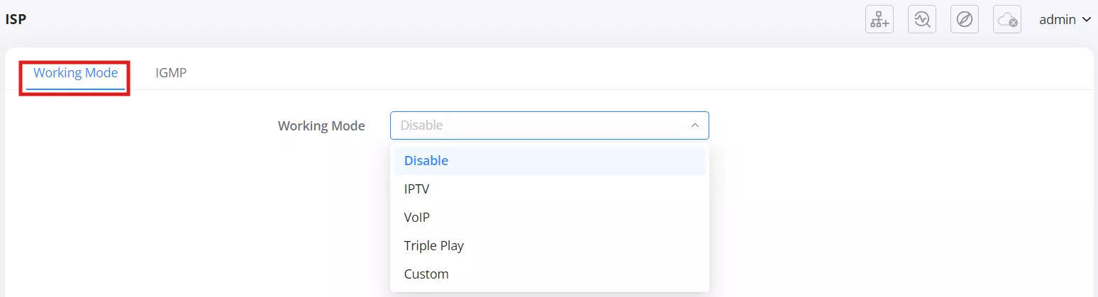
The Working Mode tab allows users to define how the router manages and separates different types of service traffic, such as Internet, IPTV, and VoIP. Each mode provides a specific configuration path to optimize network performance and assign VLANs or dedicated LAN ports for the selected service.
Users can select the preferred working mode from the dropdown list, which includes the following options:
- Disable – Deactivates service-specific VLAN configuration.
- IPTV – Enables IPTV-specific VLAN and port setup for smooth streaming.
- VoIP – Prioritizes and isolates voice communication traffic.
- Triple Play – Combines Internet, IPTV, and VoIP configurations under one setup.
- Custom – Allows advanced manual VLAN mapping for unique network requirements.
Note: When both WAN ports are active, each WAN can be configured independently under ISP settings, except in Triple Play mode, which applies a single configuration for both.
Each mode activates a different configuration interface to match its purpose. Once the desired mode is selected, users can define parameters such as VLAN IDs, priorities, and port assignments.
- Working Mode – IPTV
The IPTV mode is used to configure a dedicated VLAN and LAN port for Internet Protocol Television (IPTV) services. It isolates IPTV traffic from regular Internet data, ensuring smooth video streaming and stable performance. This feature is designed for users whose Internet Service Providers (ISPs) require VLAN tagging or port-specific assignment for IPTV set-top boxes.
Configuration Overview
When selecting IPTV from the Working Mode dropdown list, the interface displays configuration options for the IPTV setup, as shown below.
Follow the on-screen topology diagram to connect your modem and router correctly.
- Connect the modem’s LAN port to the GWN7062M WAN (2.5G Combo) port.
- Connect the IPTV device (STB or Smart TV) to the router’s dedicated IPTV LAN port.
This ensures that IPTV traffic is transmitted over a dedicated VLAN and isolated from other services.
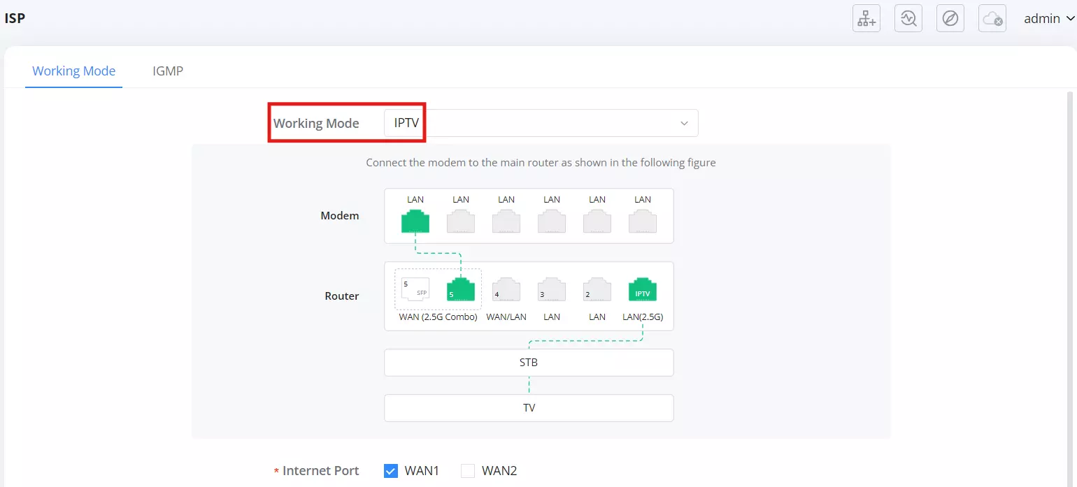
IPTV Configuration Fields
- Internet Port – You can select and configure multiple WAN ports (e.g., WAN1 and/or WAN2) to handle IPTV traffic independently when using IPTV, VoIP, or Custom working modes.
- IPTV Port – Choose the LAN port to assign for IPTV service. (e.g., Port 1, Port 2, or Port 3).
- ISP – Select your ISP profile from the predefined list or choose Custom to configure manually.
[Image 4 Placeholder]
Available ISP profiles include regional providers such as:
Malaysia-Maxis 1, Malaysia-Maxis 2, Malaysia-Unifi, Portugal-Vodafone, Singapore-Singtel, and Vietnam-Viettel. - 802.1Q Tag – Enable to apply VLAN tagging for Internet and IPTV traffic according to ISP requirements.
- Internet VLAN / IPTV VLAN – Enter VLAN IDs in the range 2–4094.
- Internet VLAN 802.1p / IPTV VLAN 802.1p – Define the VLAN priority values (0–7, where 7 is highest).
After filling in all required parameters, click Save to apply changes.
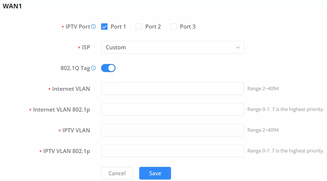
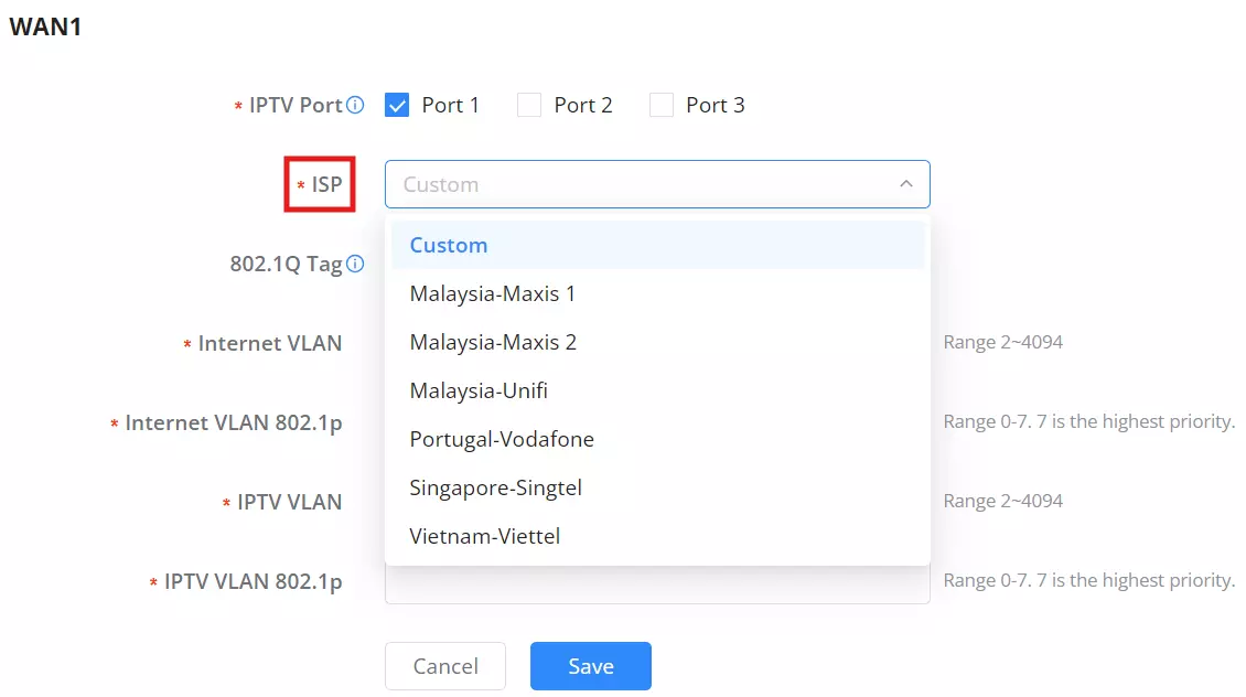
Notes:
- VLAN and priority values must match those provided by the ISP; incorrect values may prevent IPTV service from functioning.
- Each WAN interface can be configured independently under IPTV mode.
- This mode does not support Method Selection. Multicast handling is managed automatically through IGMP settings.
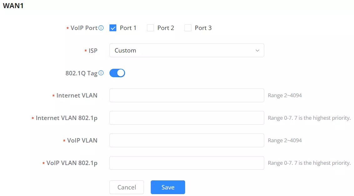
- Working Mode – VoIP
The VoIP mode is designed to optimize and isolate Voice over IP traffic for stable and high-quality communication. It enables VLAN tagging and dedicated port assignment for VoIP devices such as IP phones or ATA adapters.
This setup ensures voice packets receive higher priority on the network, reducing jitter, delay, and packet loss.
Configuration Overview
When VoIP is selected from the Working Mode dropdown list, the interface displays configuration options for assigning the Internet port, VoIP LAN port, and VLAN settings.
Follow the visual topology diagram to correctly connect the modem and router:
- Connect the modem’s LAN port to the WAN (2.5G Combo) port of the GWN7062M.
- Connect the VoIP device (e.g., IP phone) to the router’s dedicated VoIP LAN port.
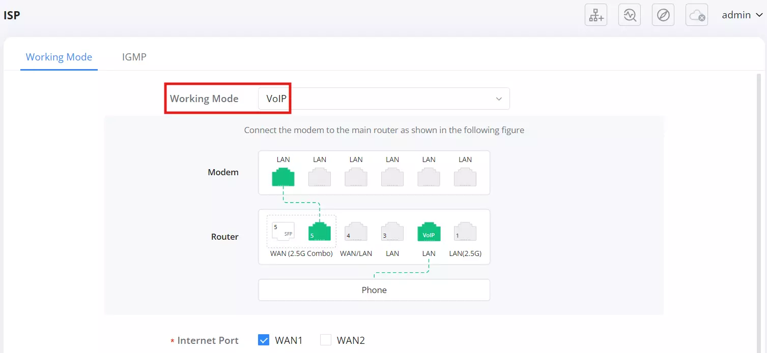
VoIP Configuration Fields
- Internet Port – Select which WAN port (WAN1 or WAN2) will carry VoIP traffic.
- VoIP Port – Choose the LAN port used for VoIP service (e.g., Port 1, Port 2, or Port 3).
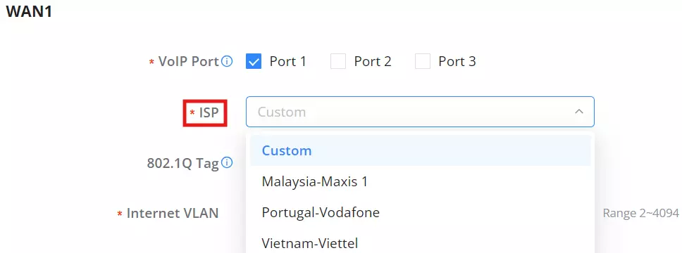
(Select the port as the VoIP port based on the connection between the modem and the main router.) - ISP – Choose the ISP profile from the predefined list or select Custom to configure manually.
Available profiles may include: Malaysia-Maxis 1, Portugal-Vodafone, and Vietnam-Viettel. - 802.1Q Tag – Enable to mark VoIP or Internet traffic with VLAN tagging.
(Configures whether to enable 802.1Q Tag to mark Internet data or not.) - Internet VLAN – Enter the VLAN ID for Internet traffic (Range: 2–4094).
- Internet VLAN 802.1p – Assign traffic priority (Range: 0–7, where 7 is the highest priority).
- VoIP VLAN – Specify the VLAN ID for VoIP traffic (Range: 2–4094).
- VoIP VLAN 802.1p – Define VLAN priority for VoIP (Range: 0–7, where 7 is the highest).
Click Save to apply the configuration.
Notes:
- Ensure VLAN IDs and priorities match your ISP’s requirements; incorrect values may cause VoIP service failure.
- Each WAN interface can be configured independently in VoIP mode.
- This mode is suitable for VoIP service providers requiring VLAN tagging or dedicated port mapping for SIP-based devices.
- Working Mode – Triple Play
Triple Play configures Internet, IPTV, and VoIP services together under a single profile.
Important: When two WANs are available, ISP settings can be configured separately per WAN for other modes. Triple Play is the exception and applies as one combined configuration. You may select which WAN interface this profile uses, but you cannot create separate Triple Play profiles for both WANs.
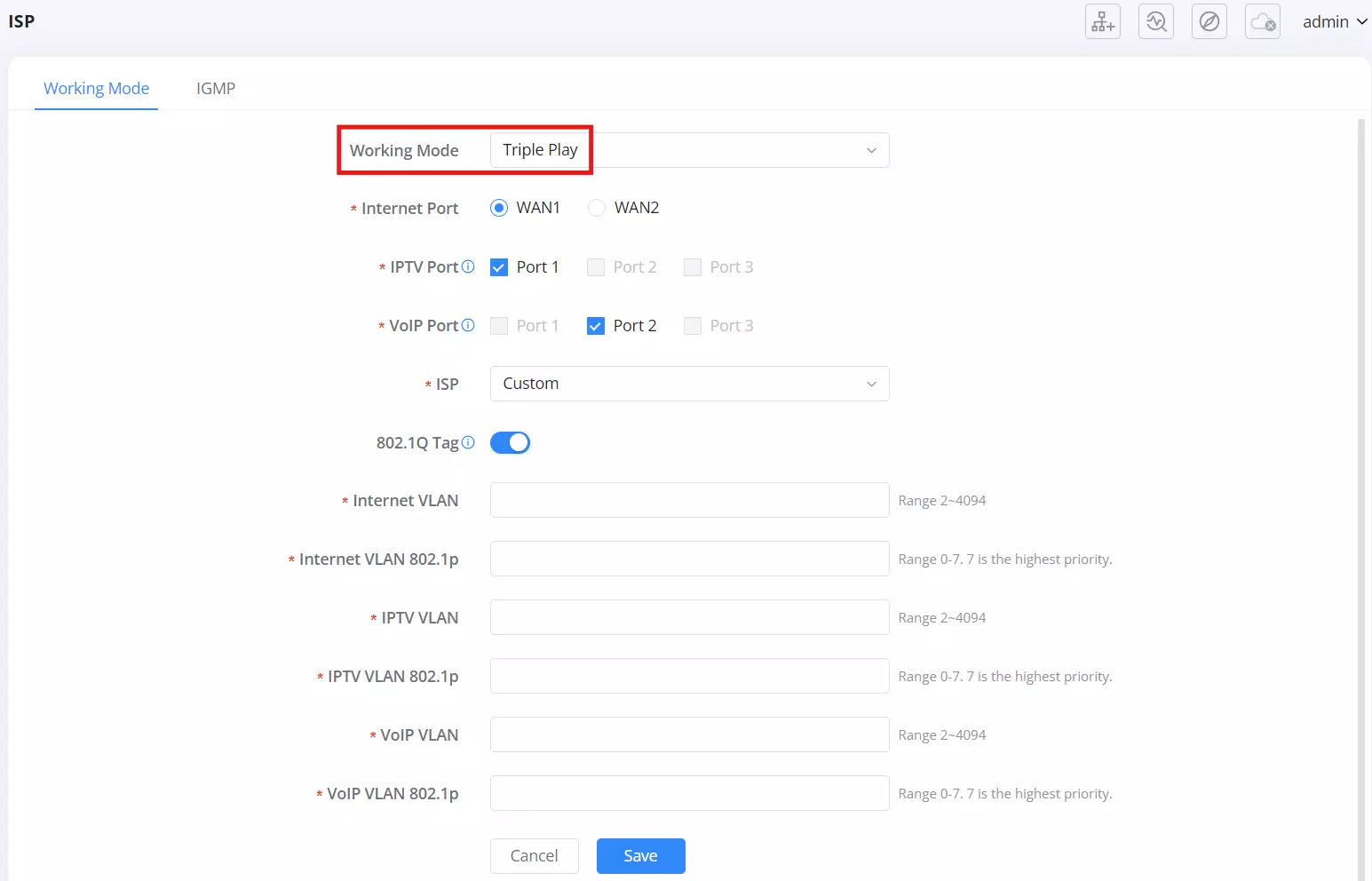
Configuration Fields
- Internet Port
Select the WAN interface used by the Triple Play profile: WAN1 or WAN2. - IPTV Port
Choose the LAN port assigned to IPTV service (Port 1 / Port 2 / Port 3).
Tooltip: Select the port as the IPTV port based on the connection mode between the modem and the main router. - VoIP Port
Choose the LAN port assigned to the VoIP service (Port 1 / Port 2 / Port 3).
Tooltip: Select the port as the VoIP port based on the connection between the modem and the main router. - ISP
Select a predefined ISP profile or Custom for manual entry.
Available options in the list: Custom, Malaysia-Maxis 1, Portugal-Vodafone, Vietnam-Viettel. - 802.1Q Tag
Toggle to enable VLAN tagging for the Internet, IPTV, and VoIP services within this profile.
Tooltip: Configures whether to enable the 802.1Q tag to mark Internet data or not. - Internet VLAN
Enter VLAN ID for Internet traffic (Range: 2–4094). - Internet VLAN 802.1p
Enter priority for Internet VLAN (Range: 0–7, where 7 is highest). - IPTV VLAN
Enter VLAN ID for IPTV traffic (Range: 2–4094). - IPTV VLAN 802.1p
Enter priority for IPTV VLAN (Range: 0–7, where 7 is highest). - VoIP VLAN
Enter VLAN ID for VoIP traffic (Range: 2–4094). - VoIP VLAN 802.1p
Enter priority for VoIP VLAN (Range: 0–7, where 7 is highest). - Save / Cancel
Click Save to apply the Triple Play configuration.
Notes:
- VLAN IDs and priority values must match your ISP’s requirements. Incorrect values will prevent the service from working.
- Triple Play uses a single WAN at a time. To split IPTV and VoIP across different WANs, configure IPTV and VoIP modes separately instead of Triple Play.
Working Mode – Custom
The Custom mode provides advanced VLAN and port mapping flexibility for complex network setups. It allows users to manually define VLAN IDs, traffic priorities, and port bridges to isolate or prioritize specific traffic types. This mode is intended for professional or enterprise users who need granular control over WAN and LAN segmentation.
Note: When both WAN ports are active, each WAN can be configured independently under ISP settings. This allows separate VLAN or port mappings per WAN.
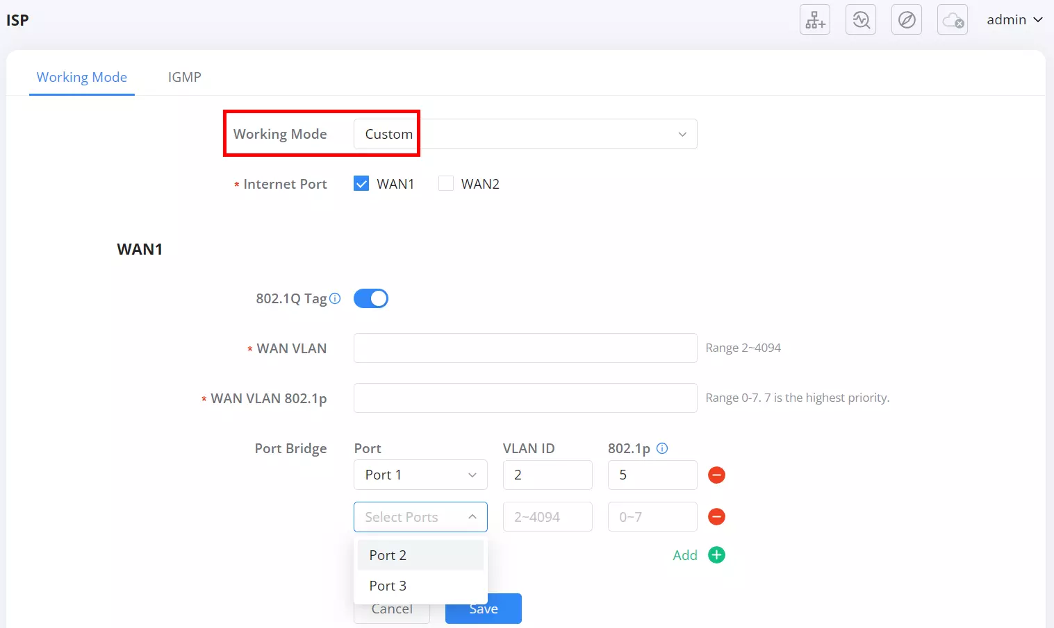
Configuration Fields:
- Internet Port
Select which WAN interface (WAN1 or WAN2) will be configured. - 802.1Q Tag
Toggle to enable VLAN tagging on the selected WAN.
Tooltip: Configures whether to enable the 802.1Q tag to mark Internet data or not. - WAN VLAN
Enter the VLAN ID for the WAN interface (Range: 2–4094). - WAN VLAN 802.1p
Set the VLAN priority (Range: 0–7, where 7 is the highest). - Port Bridge
Allows mapping of LAN ports to specific VLANs and priorities.- Port – Select which LAN port (e.g., Port 1, Port 2, or Port 3) to bridge.
- VLAN ID – Assign VLAN ID for the selected port (Range: 2–4094).
- 802.1p – Set traffic priority (Range: 0–7, where 7 is the highest).
- Add – Add additional port-VLAN entries as needed.
- Delete (–) – Remove existing VLAN entries.
Example Use Cases:
- Creating separate VLANs for guest and internal networks.
- Mapping different LAN ports to unique VLANs for department-based segmentation.
- Assigning priority values to ensure critical traffic (e.g., VoIP) receives higher bandwidth.
After all configurations are defined, click Save to apply changes.
Notes:
- Custom mode supports full manual VLAN tagging and bridging per WAN interface.
- Incorrect VLAN or priority settings may disrupt connectivity—use values provided by your network administrator or ISP.
IGMP
The IGMP tab provides multicast optimization for IPTV and streaming environments. It contains two parts: IGMP Proxy (handles multicast group membership on the WAN side) and IGMP Snooping (limits multicast flooding on the LAN by forwarding only to member ports).
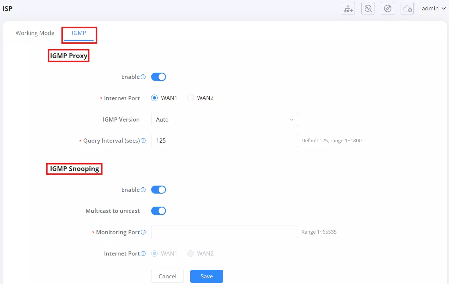
IGMP Proxy:
- Enable
Turn on IGMP Proxy.
Tooltip: After enabling, the IGMP proxy will be allowed to access any multicast group. - Internet Port
Select the WAN interface used for IGMP Proxy: WAN1 or WAN2. - IGMP Version
Choose the IGMP version used with the ISP network. (Options shown by the UI; select Auto if unsure.) - Query Interval (secs)
Set the interval for sending general IGMP queries. Default: 125. Range: 1–1800.
Tooltip: Set the sending interval of IGMP general group query messages.
Click Save to apply Proxy settings.
IGMP Snooping:
- Enable
Turn on IGMP Snooping for the LAN.
Tooltip: After enabling, multicast traffic will be forwarded to ports belonging to the group members. This configuration will apply to all LAN ports. - Multicast to unicast
Optional conversion to unicast for devices or switches that handle multicast poorly. - Monitoring Port
Enter the multicast UDP port used for monitoring. Range: 1–65535.
Tooltip: Configures the multicast UDP port of monitoring. - Internet Port
Select which WAN is monitored by Snooping: WAN1 or WAN2.
Tooltip: Set the monitored WAN port.
Click Save to apply Snooping settings.
Notes:
- Start with IGMP Version: Auto and Query Interval: 125 unless your ISP specifies different values.
- If IPTV set-top boxes still flood the LAN, enable Multicast to unicast under Snooping.
Policy Routes
Policy Routes allow administrators to steer specific traffic through a defined WAN behavior (for example, load balancing across uplinks or using a backup link). In the updated interface, routing behavior is created in Policy Pool, then applied to traffic-matching rules in Policy Routes using a Reference Policy.
This configuration is accessible via: Advanced → Internet Settings → Policy Routes.
Policy Pool
Policy Pool is where you define how traffic should leave the router. Policies created here can be reused across multiple policy route rules (Domain, Client, or VLAN).
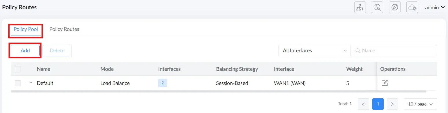
The Policy Pool page lists existing policies and their characteristics (such as mode, number of interfaces, balancing strategy, and weights).
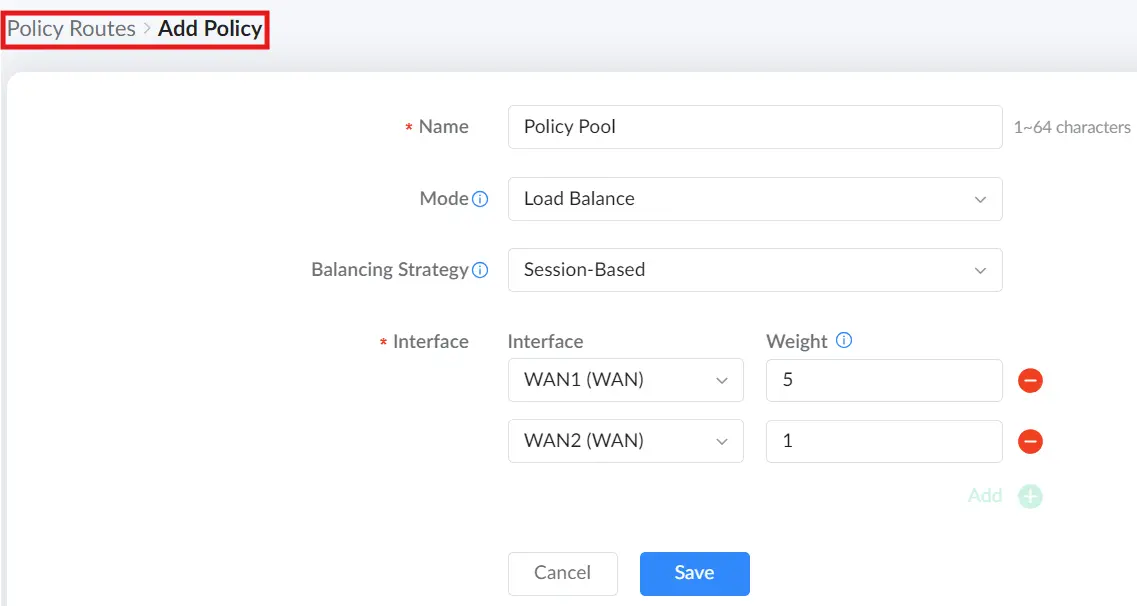
Add a Policy (Policy Pool)
- Navigate to Advanced → Internet Settings → Policy Routes → Policy Pool Tab.
- Click Add.
- Configure the policy parameters, then click Save.
The following settings determine how the router distributes traffic across the selected interfaces:
Mode
- Load Balance: Traffic is proportionally distributed based on the configured policy weights. It is recommended to allocate weights according to actual WAN bandwidth capacity.
- Backup: When the preferred interface fails, traffic switches to the backup interface. Both preferred and backup interfaces can be configured with policy weights to proportionally distribute traffic when active, helping maintain connectivity and availability.
Balancing Strategy
This setting determines how traffic is distributed across multiple connections:
- Session-Based: Traffic is distributed evenly among the links.
- Source IP Address: Traffic from the same source IP address is routed through the same interface, reducing potential access issues that can occur when traffic jumps between links.
- Source & Destination IP Addresses: Traffic between the same source and destination IP addresses is routed through the same interface, providing consistent routing for specific communication flows.
Interface and Weight
Policies can include one or more interfaces (for reminder: typically WAN uplinks). Each interface is assigned a weight to influence the distribution.
Weight: Default is 1. Enter a value from 1–10, where 10 is the highest weight.
A practical example for Load Balance is assigning a higher weight to the higher-bandwidth WAN (for example, WAN1 weight 5 and WAN2 weight 1) so more sessions prefer the faster link.
Policy Routes
Policy Routes define what traffic matches a routing rule (Domain, Client, or VLAN). Each rule then selects a Reference Policy from the Policy Pool to determine how that matched traffic is routed.
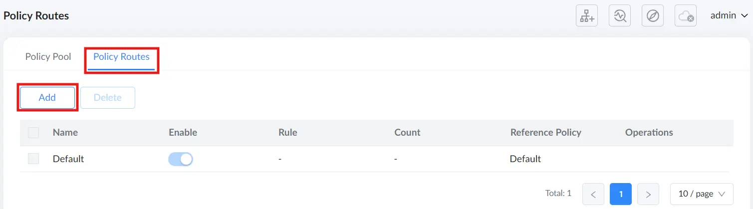
Add a Policy Route
- Navigate to Advanced → Internet Settings → Policy Routes → Policy Routes Tab.
- Click Add.
- Enter a Name and enable the rule if required.
- Select the Rule type (Domain, Client, or VLAN).
- Select a Reference Policy (Policy Pool entry) to apply.
- Click Save.
The sections below describe each rule type.
Domain Rule
Use Domain rules to route traffic destined for specific domain names through a chosen Policy Pool entry.
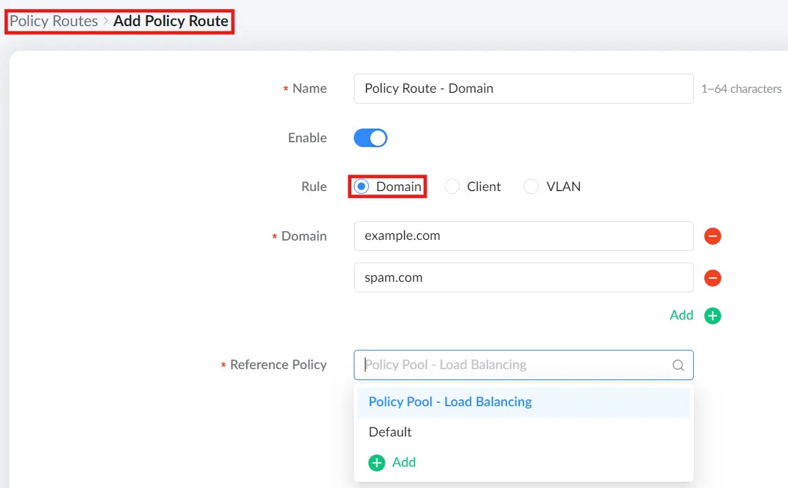
In the Add Policy Route window:
- Set Rule to Domain.
- Enter one or more domains (for example,
example.com). Use the Add (+) control to include multiple domains. - Under Reference Policy, select the required Policy Pool entry (for example, a load-balancing policy or a backup policy).
- Click Save.
This ensures that traffic associated with the specified domains follows the WAN behavior defined in the selected Policy Pool policy.
Client Rule
Client rules route traffic from specific client devices through a selected Policy Pool entry. Clients can be chosen from the connected client list or added manually.
Client selection note (important): If the client uses a random MAC address, the MAC value may be inaccurate. For reliable matching, ensure the client device uses a static MAC address (disable random MAC on the client device if needed).
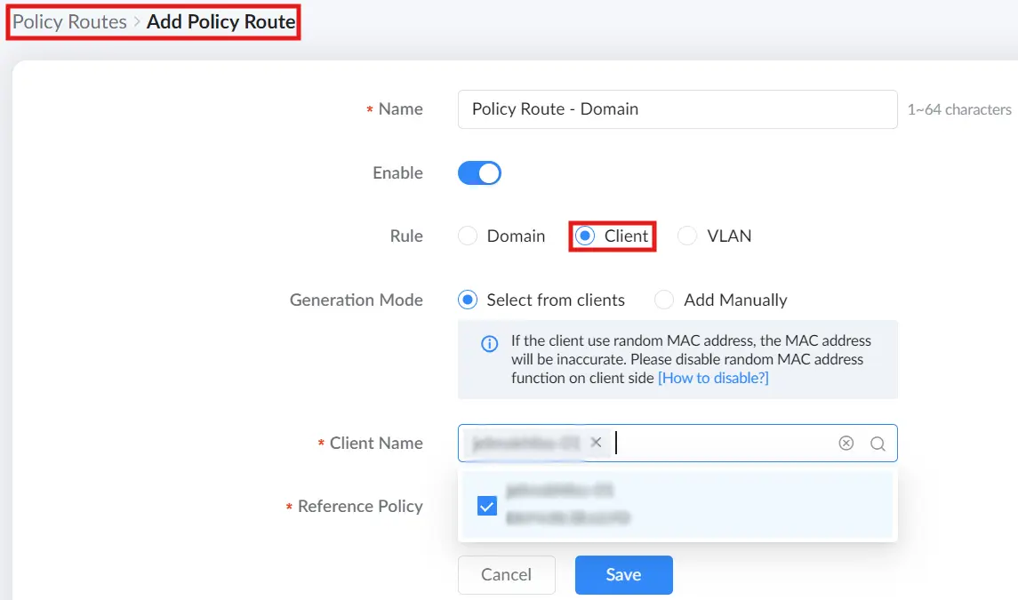
Select from clients
- Set Rule to Client.
- Under Generation Mode, choose Select from clients.
- Select the Client Name from the list.
- Select the Reference Policy (Policy Pool entry).
- Click Save.
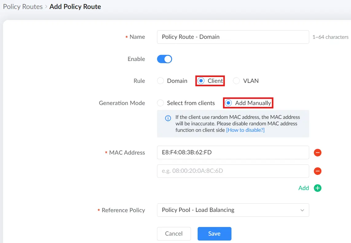
Add Manually
- Set Rule to Client.
- Under Generation Mode, choose Add Manually.
- Enter the client MAC Address. Use Add (+) if you need to include multiple MAC addresses.
- Select the Reference Policy (Policy Pool entry).
- Click Save.
This approach is useful for devices that do not appear in the client list but must follow a specific routing policy.
VLAN Rule
VLAN rules route traffic associated with a specific VLAN through a selected Policy Pool entry. This is commonly used in segmented networks (for example, separate VLANs for voice, IPTV, or guest access).
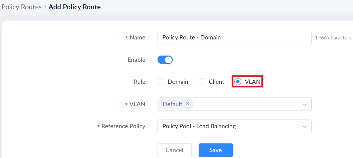
In the Add Policy Route window:
- Set Rule to VLAN.
- Select the target VLAN from the dropdown list.
- Select the Reference Policy (Policy Pool entry).
- Click Save.
This ensures traffic for the selected VLAN follows the WAN behavior defined in the referenced Policy Pool policy.
Wi-Fi Settings
Wi-Fi
The Wi-Fi page is where you create and manage wireless networks (SSIDs). From this page, you can enable or disable an SSID, review its band and security settings, edit configuration options, share access via QR code, or delete the SSID.
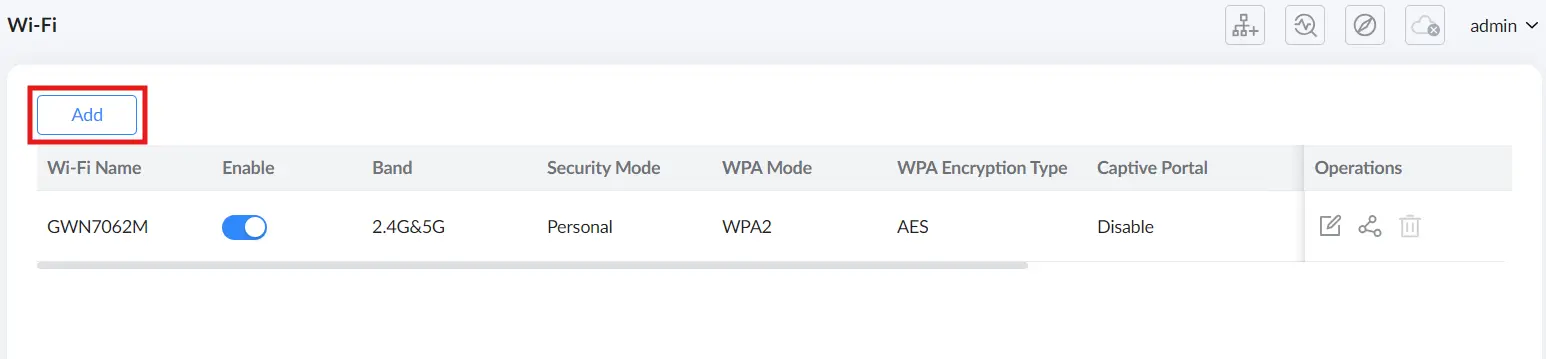
The SSID list provides a quick overview of each wireless network, including its band, security configuration, captive portal status, connected clients, VLAN association, and traffic statistics. Use the Enable toggle to turn an SSID on or off. Under Operations, you can edit the SSID settings, share the SSID via QR code, or delete it.
Add or edit a Wi-Fi network
- Navigate to Advanced → Wi-Fi Settings → Wi-Fi.
- Click Add to create a new SSID, or click the Edit icon to modify an existing one.
- Configure the required settings, then click Save.
The Add/Edit Wi-Fi page includes Basic Settings and Advanced Settings.
- Basic Settings
The Basic Settings section defines the SSID identity, radio band selection, and security method. Available fields and behavior depend on the selected Security Mode.
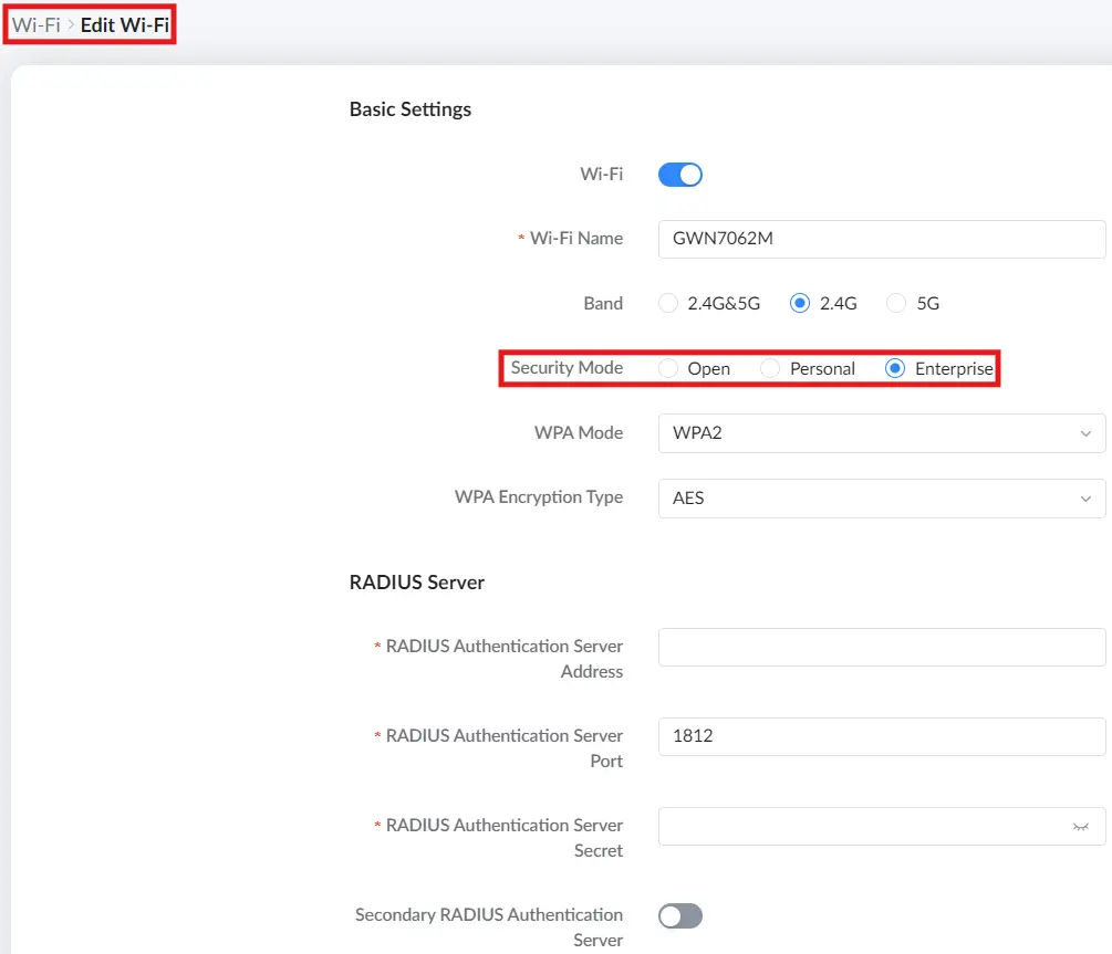
Field | Description |
Wi-Fi | Enables or disables this SSID. |
Wi-Fi Name | SSID name (1–32 characters). This is what clients see when scanning for networks (unless Hidden Wi-Fi is enabled). |
Band | Select the radio band for this SSID: 2.4G&5G, 2.4G, or 5G. |
Security Mode | Select Open, Personal, or Enterprise. This selection determines which authentication options appear. |
WPA Mode | Available when using Personal or Enterprise security. Options: WPA/WPA2, WPA2, WPA2/WPA3, WPA3. (check the table below for more details) |
WPA Encryption Type | Select the encryption algorithm used by the SSID. Options: AES, AES/TKIP, GCMP-128, GCMP-256 and CCMP-256. (check the table below for more details) |
Password | Available only when Security Mode = Personal. Password must be 8–63 ASCII characters or 8–64 hex characters. |
RADIUS Server (Enterprise only) | When Security Mode = Enterprise, RADIUS fields become available (for example, server address, port, and shared secret). |
Add/Edit Wi-Fi – Basic Settings
Wi-Fi Security Mode & WPA options:
Security Mode | WPA Mode | WPA Encryption Mode |
Open | x | x |
Personal | WPA/WPA2 | AES (Default); AES/TKIP |
WPA2 | AES (Default); AES/TKIP | |
WPA2/WPA3 | AES (Default) | |
WPA3 | AES (Default) | |
Enterprise | WPA/WPA2 | AES (Default); AES/TKIP |
WPA2 | AES (Default); AES/TKIP | |
WPA2/WPA3 | AES (Default); GCMP-128 | |
WPA3 | AES (Default); GCMP-128 | |
WPA3-192 | GCMP-256 (Default); CCMP-256 |
Wi-Fi Security Mode & WPA options
- Advanced Settings
The Advanced Settings section controls SSID visibility, VLAN mapping, captive portal assignment, scheduling, and how “professional” Wi-Fi behavior is applied to the SSID.
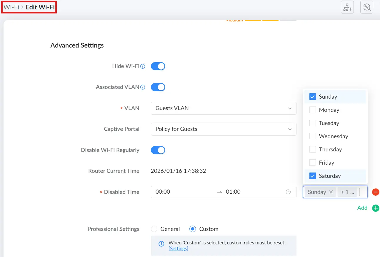
Field | Description |
Hide Wi-Fi | When enabled, the SSID is not broadcast. Clients must manually enter the SSID name to connect. |
Associated VLAN | Enables VLAN binding for this SSID. When enabled, you can select the VLAN to associate with this Wi‑Fi network. When disabled, the SSID uses the default VLAN. |
VLAN | Available when Associated VLAN is enabled. Select the VLAN to bind to this SSID. |
Captive Portal | Select a captive portal policy to apply to this SSID, or set to Disable to allow direct access without a portal. |
Disable Wi-Fi Regularly | Enables scheduled Wi‑Fi disabling. When enabled, configure the schedule to automatically turn this SSID off during specified times. |
Router Current Time | Displays the router’s current time, used as the reference for scheduling. |
Disabled Time | The time range during which this SSID will be disabled. |
Days (selection) | Select the days of the week the schedule applies to. You can choose multiple days. |
Professional Settings | Select General to use the system default professional profile, or Custom to apply custom professional settings. When Custom is selected, custom rules must be configured/reset via the linked settings page. |
Add/Edit Wi-Fi – Advanced Settings
Share Wi-Fi using a QR code
To share an SSID quickly with guests, use the QR code function:
- On the Wi-Fi list page, click the Share icon for the SSID.
- A QR code is displayed for clients to scan and connect.
- Click Save QR code to download the QR code image.
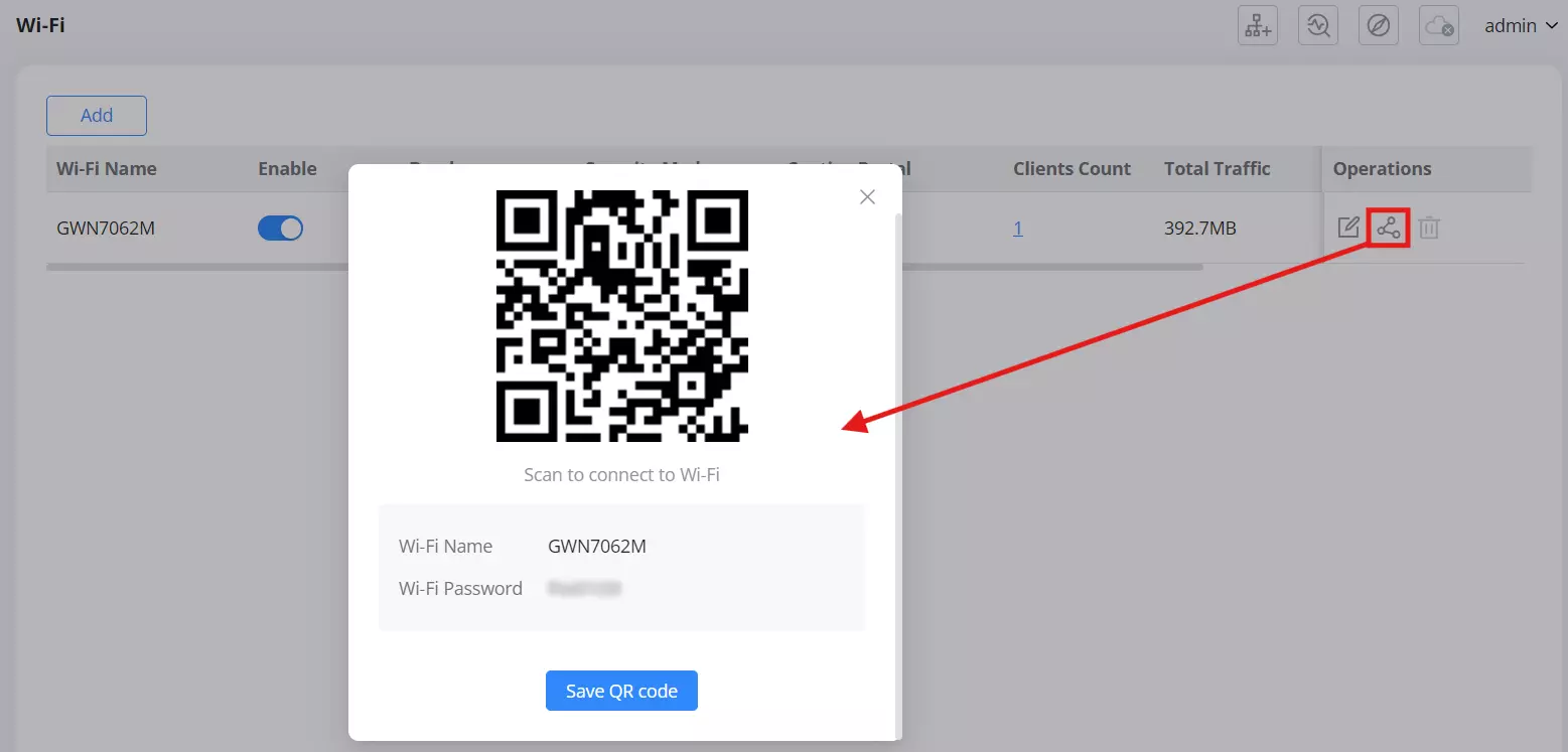
Guest Wi-Fi
Guest Wi-Fi lets you provide visitors with a separate wireless network profile, typically used to limit access and apply guest-specific settings (such as captive portal policies). It’s designed for quick deployment of a visitor SSID without changing your primary Wi-Fi configuration.
To access this page, navigate to: Advanced → Wi-Fi Settings → Guest Wi-Fi
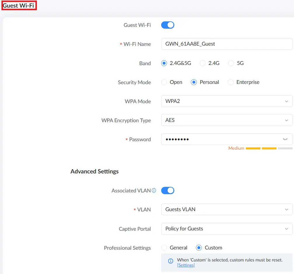
Configure the Guest Wi-Fi SSID using the options below, then click Save.
Field | Description |
Guest Wi-Fi | Enables or disables the guest SSID. |
Wi-Fi Name | SSID name guests will see (1–32 characters). |
Band | Select where the SSID is broadcast: 2.4G&5G, 2.4G, or 5G. |
Security Mode | Select the security type: Open, Personal, or Enterprise. |
WPA Mode | Available when using Personal or Enterprise security. Options: WPA/WPA2, WPA2, WPA2/WPA3, WPA3. (check the table below for more details) |
WPA Encryption Type | Select the encryption algorithm used by the SSID. Options: AES, AES/TKIP, GCMP-128, GCMP-256 and CCMP-256. (check the table below for more details) |
Password | Pre-shared key for the SSID when using Personal security. |
RADIUS Authentication Server Address | Primary RADIUS server address for Enterprise security. |
RADIUS Authentication Server Port | RADIUS authentication port for Enterprise security. |
RADIUS Authentication Server Secret | Shared secret for RADIUS authentication (Enterprise security). |
Secondary RADIUS Authentication Server | Enable and configure a secondary/backup RADIUS server (Enterprise security). |
Advanced Settings | |
Associated VLAN | Bind the guest SSID to a specific VLAN for traffic segmentation. |
VLAN | Select the VLAN used by the guest SSID when VLAN association is enabled. |
Captive Portal | Apply a captive portal policy to guest clients (optional). |
Professional Settings | Use General defaults or Custom settings (Custom may require additional configuration under General Settings). |
Guest Wi-Fi page
Wi-Fi Security Mode & WPA options:
Security Mode | WPA Mode | WPA Encryption Mode |
Open | x | x |
Personal | WPA/WPA2 | AES (Default); AES/TKIP |
WPA2 | AES (Default); AES/TKIP | |
WPA2/WPA3 | AES (Default) | |
WPA3 | AES (Default) | |
Enterprise | WPA/WPA2 | AES (Default); AES/TKIP |
WPA2 | AES (Default); AES/TKIP | |
WPA2/WPA3 | AES (Default); GCMP-128 | |
WPA3 | AES (Default); GCMP-128 | |
WPA3-192 | GCMP-256 (Default); CCMP-256 |
Wi-Fi Security Mode & WPA options
Wi-Fi General Settings
Wi-Fi General Settings provides device-wide wireless tuning for both 2.4 GHz and 5 GHz radios. Use this section to control channel behavior, channel width, transmit power, and roaming-related features. It’s the place you go when you care about stability, roaming quality, and RF performance.
To access this page, navigate to: Advanced → Wi-Fi Settings → General Settings.
Common Settings
The Common Settings tab contains core RF configuration for both bands (2.4G and 5G), including how channels are selected and how aggressively the radios transmit.
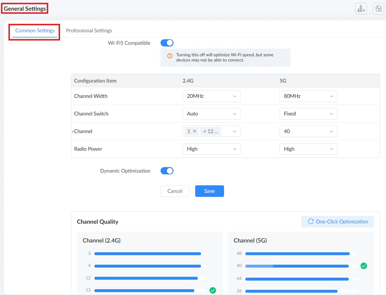
Field | Description |
Wi-Fi5 Compatible | Enable to improve compatibility with Wi-Fi 5 (802.11ac) clients. Disabling may improve Wi-Fi performance, but some devices may not be able to connect. |
Channel Width | Select the channel bandwidth for each band (2.4G and 5G). Wider bandwidth may increase throughput but can be more sensitive to interference. |
Channel Switch | Select how the device chooses the operating channel for each band.
|
Channel | Specify the channel list/target channel for each band. When Channel Switch is set to Auto, select one or more allowed channels and the device will automatically choose among them. When set to Fixed, select a specific channel to use. (2.4G supports multi-select; 5G is selected from a drop-down list.) |
Radio Power | Set the transmit power level for each band (High/Medium/Low). Higher power increases coverage but may increase interference. |
Dynamic Optimization | Enable to allow the device to dynamically optimize wireless performance based on the environment. |
Channel Quality | Displays channel quality information for 2.4G and 5G to help identify less congested channels. |
One-Click Optimization | Automatically optimizes channel-related settings based on current channel quality to improve wireless performance. |
Common Settings
Professional Settings
The Professional Settings tab controls advanced roaming and client-handling features. These settings are especially relevant in deployments with multiple APs and roaming clients (voice devices, mobile terminals, etc.).
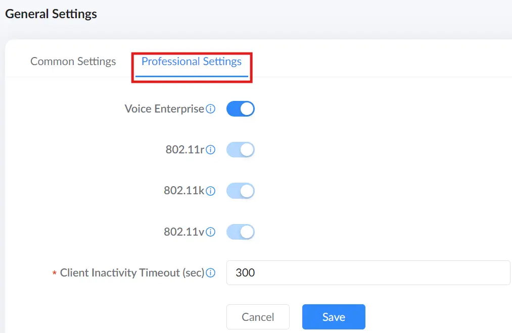
Field | Description |
Voice Enterprise | Optimizes Wi-Fi parameters for latency-sensitive voice traffic. When enabled, 802.11r/k/v are forced ON and locked. Not effective for Open encryption. |
802.11r | Fast roaming standard that reduces authentication time during handoff for seamless roaming. Not effective for Open encryption. |
802.11k | Provides roaming assistance information to clients to improve access-point selection. |
802.11v | Enables network-assisted client steering to improve roaming behavior and overall performance. |
Client Inactivity Timeout (sec) | Disconnects clients that generate no traffic within the configured time duration. |
Professional Settings
Mesh
Mesh lets you extend coverage by adding compatible Grandstream devices as Mesh nodes to a primary router. A node can be another router (for example, GWN7062E(ET) or GWN7062M) or a supported access point (for example, GWN7660EM). The Add wizard starts by asking for the node model because the preparation and pairing guidance depend on that selection.
Adding a Mesh node
Use the Mesh page to view existing nodes and start the Add wizard.
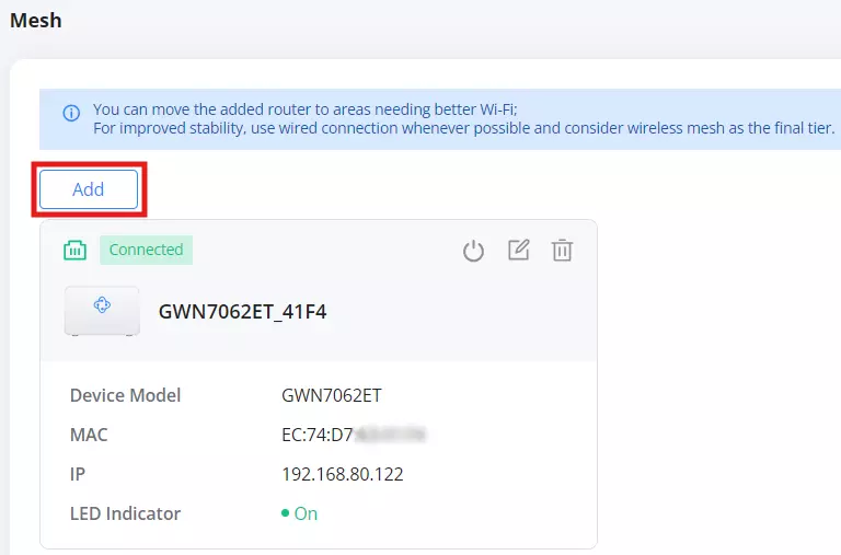
Open the Mesh page by going to Advanced → Mesh, then click Add to start the wizard.
On the Select Node Model screen, choose the model you are adding (router or access point), then click Next. This step matters because the next two pages (Preparations and Networking Method) are tailored to the model you selected.
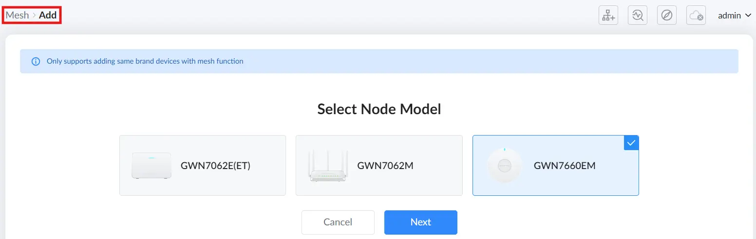
On the Preparations page, the wizard shows requirements for both the primary router and the node device. For the primary router, ensure it is powered on, connected to the network, and ready (the UI typically indicates this with a solid blue LED). For the node device, the steps are model-specific. Follow the on-screen instructions for the selected model, including the required button actions and LED indications, until the wizard indicates the device is ready. Then click Preparation Complete.
Follow the model-specific preparation steps shown by the wizard.
- Preparations – GWN7062E(ET) & GWN7062M
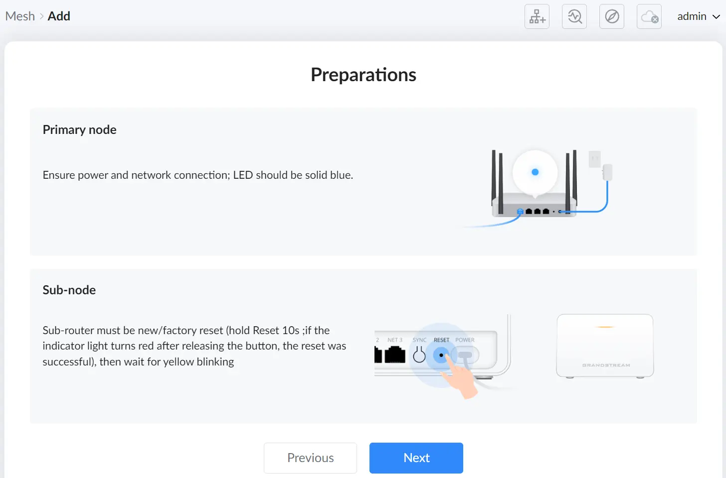
- Preparations – GWN7660EM
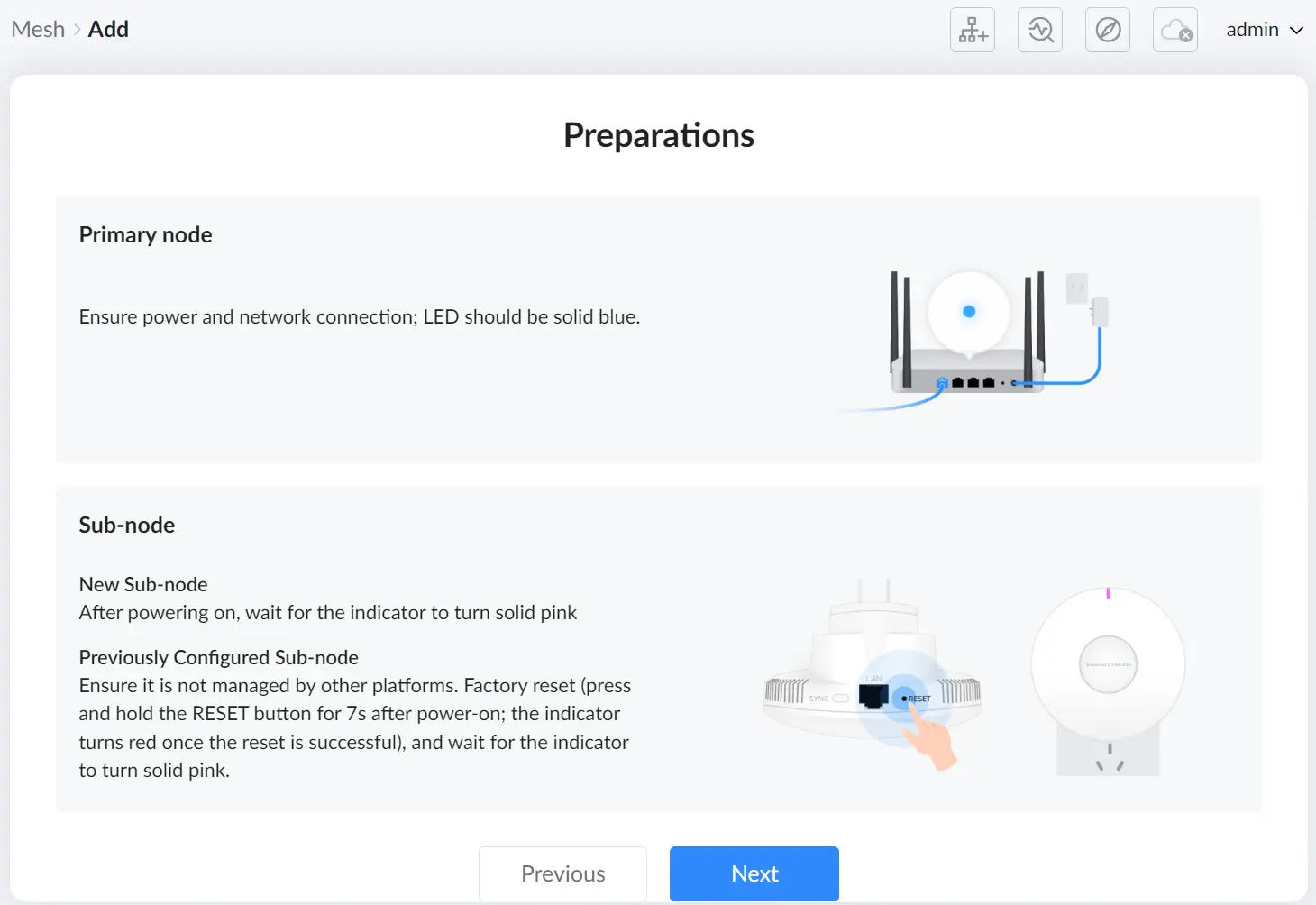
On the Networking Method page, select how the node will connect during setup. The wizard marks the recommended option and provides model-specific diagrams. Follow the method you choose exactly as shown on-screen, then click Start adding to begin discovery.
Choose the networking method shown by the wizard, then start discovery.
- Networking Method – GWN7062E(ET) & GWN7062M
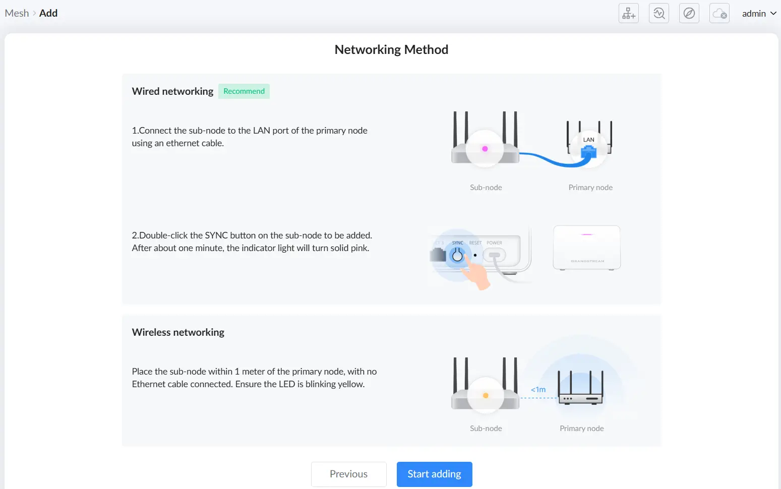
- Networking Method – GWN7660EM
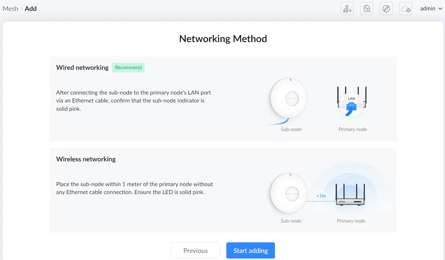
The wizard then searches and lists discovered devices.
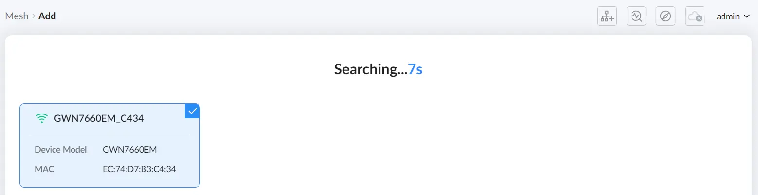
When a device appears, select it from the list. The entry shows identifying information such as device model and MAC address.
If the wizard prompts for a final action on the node (for example, pressing the SYNC button), complete the action as instructed on-screen to finish pairing. If the method is wired, clicking the sync button is not necessary.
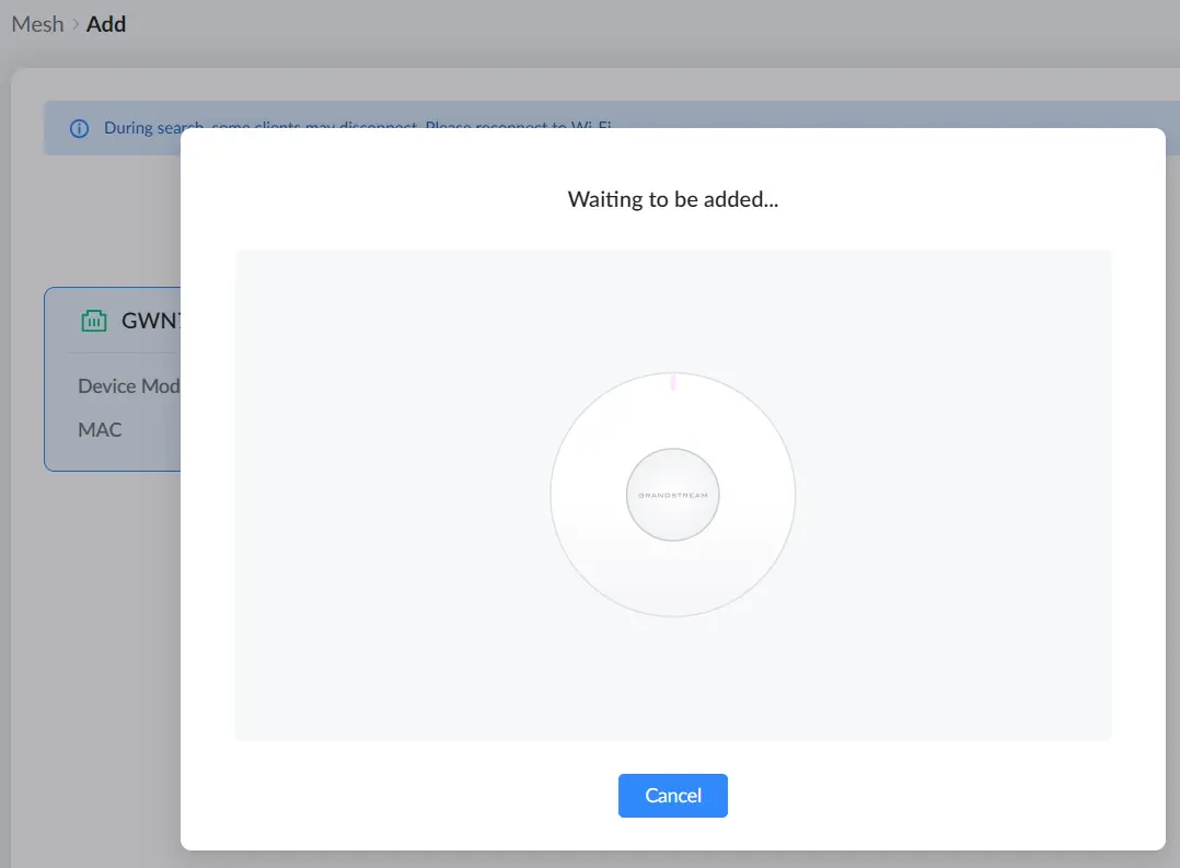
After pairing completes, you return to the Mesh page where the node appears with a Connected status and device details such as model, MAC address, IP address, and LED indicator state.
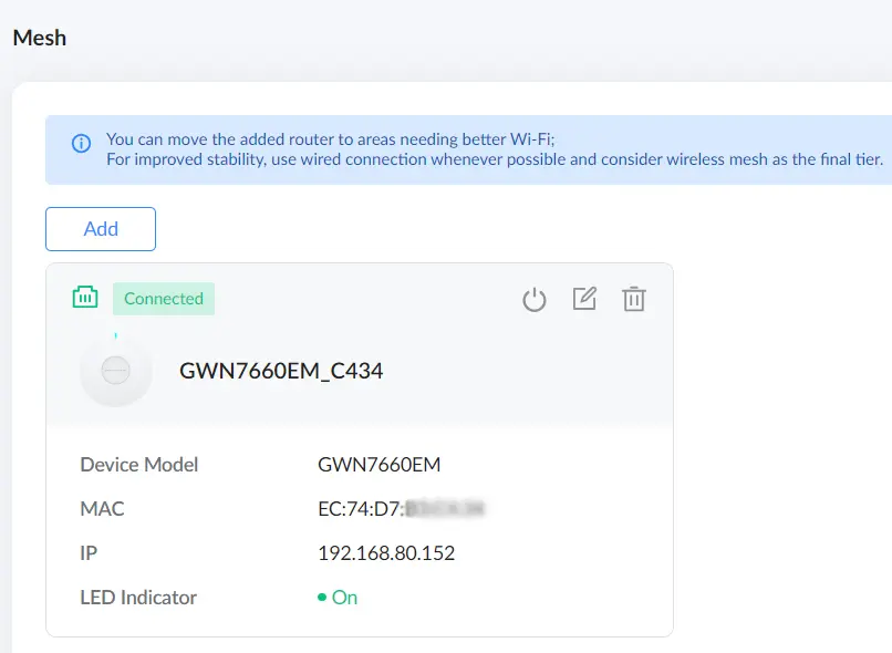
Managing a Mesh node
Use the node card actions to manage a joined device.
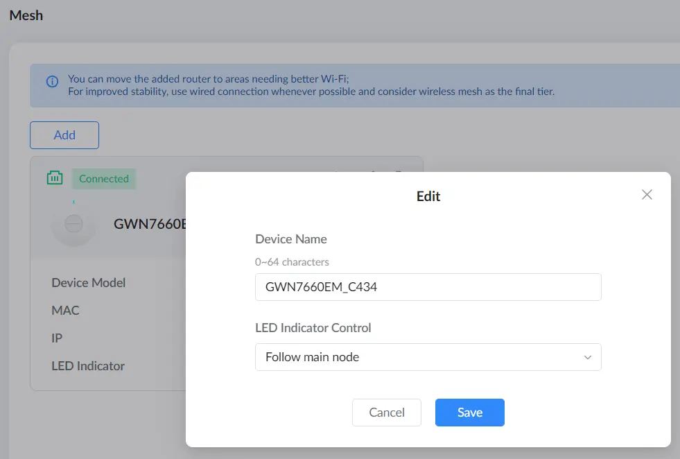
Each connected node card provides quick actions such as rebooting the node and opening the edit dialog. In the Edit dialog, you can rename the device and adjust LED Indicator Control (for example, setting it to follow the main node), then click Save to apply your changes.
Clients
The Clients page on the router provides an overview of all connected devices, including both wired and wireless clients. This section allows users to monitor connected clients, view real-time traffic statistics, and manage client access. Users can rename devices, assign static IPs, analyze traffic statistics, and block unwanted clients.
Accessing the Clients Page
- Navigate to Advanced → Clients in the left sidebar.
- The Clients page will display a list of all connected devices, including:
- Device Name
- IP Address (IPv4/IPv6)
- Connection Type (2.4G, 5G, or Wired)
- Real-Time Data Rate
- Total Data Usage
- Current Traffic
- Available operations for each client

Modifying a Client Name
- Click on the Edit (pencil) icon next to the client name.
- Enter a new name in the pop-up window.
- Click Save to apply the changes.

Viewing Client Traffic Details
- Click on the Exclamation mark icon next to a client entry.
- This opens a Client Traffic Overview page with:
- Traffic statistics by app group
- Data usage trends over time (Today, This Week, or This Month)
- Breakdown of applications consuming network resources

Binding a Static IP to a Client
- Click on the Link (chain) icon next to the client.
- A confirmation prompt will appear: “Confirm to bind this client to the IP address?”
- Click OK to assign a static IP to the client.

Blocking a Wireless Client
- Click on the Block (circle with a slash) icon next to the client.
- A confirmation prompt will appear: “Confirm to add this client to the blocklist?”
- Click Add to blocklist to prevent the device from reconnecting to the network.
- Note: Blocking is only effective for wireless clients.

Disabling Client Random MAC Address
Many modern operating systems use random MAC addresses as a privacy feature. However, for certain router functions such as Parental Control, Address Binding, Policy Routes, and Blocklist, a static MAC address is required.
To ensure proper operation, users should disable random MAC addresses for their specific Wi-Fi network. Below is a general method to do so, followed by examples for Windows®, iOS®, and Android®.
General Steps to Disable Random MAC Address:
- Navigate to Wi-Fi settings on your device.
- Locate the network you are connected to.
- Open network properties or advanced settings.
- Find the MAC Address Type / Privacy Settings option.
- Select Use Device MAC / Phone MAC / Fixed MAC instead of Randomized MAC.
- Save and reconnect to the network.
- Windows® (Example: Windows® 10/11)
- Go to
Settings→Network & Internet→Wi-Fi. - Click on
Manage known networks. - Select your Wi-Fi network and click
Properties. - Scroll down to
Random hardware addresses. - Toggle the option Off.

- iOS® (Example: iOS® 14 and later)
- Open
Settings→Wi-Fi. - Tap on the (i) information icon next to your Wi-Fi network.
- Tap
Private Wi-Fi Address. - Select Off.

- Android® (Examples: Stock Android, Samsung®, Xiaomi)
Stock Android:
- Go to
Settings→Network & Internet→Wi-Fi. - Tap on your connected network.
- Tap
PrivacyorMAC Address Type. - Select Use device MAC instead of
Use randomized MAC.

Samsung® Devices:
- Go to
Settings→Connections→Wi-Fi. - Tap on your connected network.
- Scroll to
MAC Address Type. - Select Phone MAC instead of
Randomized MAC.

Xiaomi Devices:
- Go to
Settings→Wi-Fi. - Tap on your connected network.
- Scroll down to
Privacy. - Select Use device MAC instead of
Use randomized MAC.

Traffic Management
Traffic Statistics
The Traffic Statistics page on the router provides detailed insights into network traffic usage. This section helps users monitor bandwidth consumption by different applications and categorize traffic usage over time. Users can filter traffic by application groups, review real-time data usage, and set QoS rules based on traffic patterns.

Accessing the Traffic Statistics Page:
- Navigate to Advanced → Traffic Management → Traffic Statistics in the left sidebar.
- The page displays two main charts:
- App Group Traffic Statistics: A pie chart showing traffic distribution across different application categories.
- App Traffic Statistics: A breakdown of specific applications contributing to network usage.
Filtering Traffic Data:
- Users can filter traffic data based on time periods:
- Today
- This Week
- This Month
- The right-side drop-down menu allows filtering by App Groups, including:
- Gaming
- Amusement
- Sociality
- Life
- Official
- VoIP
- Study
Viewing Application Traffic Details:
- Hovering over the App Traffic Statistics chart reveals detailed upload and download statistics for each application.
- The App List table provides:
- Application Name
- Traffic Category (App Group)
- Number of Visits
- Percentage of Total Traffic
- Total Data Usage (Upload & Download)
Accessing QoS Settings:
- Each application entry includes a QoS link that allows users to configure Quality of Service rules for better traffic management.
QoS
The QoS (Quality of Service) feature on the router enables users to optimize and control network traffic based on priority settings. It allows for the allocation of bandwidth to specific applications, clients, or traffic types, ensuring better performance for critical services like gaming, VoIP, and streaming. Users can configure QoS rules based on traffic type, application, or device priority.
Accessing the QoS Settings:
- Navigate to Advanced → Traffic Management → QoS to access the QoS settings.
- The QoS page consists of three main tabs:
- Basic Settings – Enables QoS and sets bandwidth limits.
- APP QoS – Allows setting priority levels for application categories.
- QoS Rules – Defines custom rules for prioritizing specific clients, applications, or domains
Enabling QoS and Setting Bandwidth (Basic Settings):
- Enable QoS: Toggle the switch to activate QoS.
- Set Maximum Bandwidth:
- Users can define upload and download speed limits for WAN1 and WAN2 connections.
- Configure Priority Settings:
- Assign priority levels (0 to 7), minimum bandwidth, and rewrite DSCP (Differentiated Services Code Point) values to optimize traffic flow.
Important Note: If bandwidth settings are not configured properly, QoS will not function as expected.

Configuring APP QoS:
- Navigate to the APP QoS tab.
- Click “Configure Priority” to assign a priority level to different application groups or individual applications.
- The available priority levels range from Priority 0 (highest) to Priority 7 (lowest).
- Users can classify traffic based on categories such as:
- Gaming
- VoIP
- Social Media
- Streaming
- Work & Study
- Selecting a higher priority ensures better bandwidth allocation for critical applications.

Adding a Custom QoS Rule:
- Go to the QoS Rules tab.
- Click “Add” to create a new QoS rule.
- Configure the following parameters:
- Name: Enter a descriptive rule name.
- Source: Choose between all clients, specific clients, or an IP address.
- Destination: Select All Traffic, Applications, or Domain.
- Apps: If applicable, select the app or app category to prioritize.
- Priority: Assign a priority level from 0 (highest) to 7 (lowest).
- Rewrite DSCP: Adjust DSCP settings if necessary.
- Click “Save” to apply the rule.

- Configure the following parameters:
- Name: Enter a descriptive rule name.
- Source: Choose between all clients, specific clients, or an IP address.
- Destination: Select All Traffic, Applications, or Domain.
- Apps: If applicable, select the app or app category to prioritize.
- Priority: Assign a priority level from 0 (highest) to 7 (lowest).
- Rewrite DSCP: Adjust DSCP settings if necessary.
- Click “Save” to apply the rule.

NAT
Port Forwarding
Port forwarding is a feature that allows external devices to communicate with devices on a local network through a specific port or range of ports. This is essential for hosting services such as web servers, gaming servers, or remote access applications. By configuring port forwarding, users can direct incoming network traffic from the WAN (Wide Area Network) to a designated IP address within the LAN (Local Area Network).
Accessing the Port Forwarding Page:
- Navigate to the Router’s Web Interface
- Log in to the router Web UI.
- From the left-side menu, expand the NAT section.
- Click on Port Forwarding.
- Adding a New Port Forwarding Rule
- On the Port Forwarding page, click the “Add” button to create a new forwarding rule.

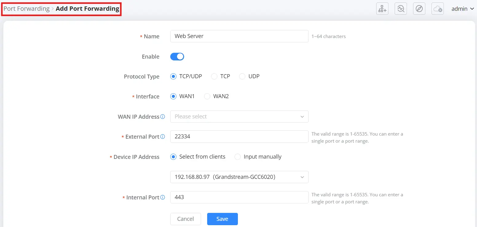
Configuring the Port Forwarding Rule:
- Name: Enter a descriptive name for the rule (e.g., “Web Server”).
- Enable: Toggle the switch to enable or disable the rule.
- Protocol Type: Select the desired protocol:
- TCP/UDP (both protocols)
- TCP only
- UDP only
- Interface: Choose the WAN interface for this rule (WAN1 or WAN2).
- WAN IP Address: Used when the WAN interface has multiple public IP addresses. Selecting a specific IP binds this rule to that address, which is useful if your ISP provides multiple static IPs and you want this service reachable through one of them only. If your WAN uses a dynamic IP that changes frequently, or you don’t need to restrict access to a single address, leave this field empty. In that case, the router automatically applies the rule to all IPs on the chosen interface so external users can still reach the internal server without manual updates.
- External Port: Specify the external port(s) that will receive incoming traffic.
Note: The external port should be within the valid range of 1-65535. - Device IP Address: Select a target device from the list of connected clients or manually enter the IP address of the internal device.
- Internal Port: Specify the internal port(s) where traffic should be forwarded.
Note: If a range of ports is used, the internal and external port ranges must match.
Understanding the Port Forwarding Notes:
- External Port Note: This port is open to the internet, allowing external users to send requests.
- Internal Port Note: This is the destination port inside the local network. If a port range is specified, the difference between the starting and ending ports must remain consistent.
DDNS
Dynamic DNS (DDNS) allows users to associate a domain name with a changing dynamic IP address. This feature is useful for users who host services at home or in environments where the public IP address frequently changes. By enabling DDNS, users can access their network remotely using a domain name instead of remembering a changing IP address.
Accessing the DDNS Settings:
- Log in to the Router Web UI.
- Navigate to NAT → DDNS.
- Click on “Add” to configure a new DDNS entry.

Configuring DDNS:
- Service Provider:
- Select a supported DDNS service provider:
- NO-IP
- DynDNS
- Users must have an account with the chosen provider.
- Select a supported DDNS service provider:
- Enable DDNS:
- Toggle the Enable switch to activate DDNS.
- Account Credentials:
- Username: Enter the registered username from the DDNS provider.
- Password: Enter the corresponding password.
- Domain: Input the registered DDNS domain (e.g.,
myrouter.no-ip.com).
- Interface Selection:
- Choose the WAN interface to associate with the DDNS:
- WAN1
- WAN2
- Choose the WAN interface to associate with the DDNS:
- IP Source:
- Choose how the IP address should be obtained:
- WAN IP (Default) – Uses the router’s WAN IP.
- Public IP – Uses the detected public-facing IP.
- Choose how the IP address should be obtained:
- Update Interval:
- Set the frequency for updating the DDNS record.
- Default: 10 minutes (Range: 1 – 1440 minutes).
UPnP
Universal Plug and Play (UPnP) is a feature that allows devices on a local network to automatically configure port forwarding on the router. This is useful for applications such as online gaming, video conferencing, and peer-to-peer connections, where port forwarding is required for seamless communication.
Accessing the UPnP Settings:
- Log in to the Router Web UI.
- Navigate to NAT → UPnP.
- The UPnP settings page will be displayed.

Configuring UPnP:
- Enable UPnP:
- Toggle the UPnP switch to activate the feature.
- Once enabled, devices on the LAN can request the router to handle port forwarding automatically.
- Select the Interface:
- WAN1 (default) or WAN2 can be chosen for UPnP operation.
- Saving the Configuration:
- Click “Save” to apply the changes.
Security Considerations:
- While UPnP simplifies port forwarding, it may pose security risks if enabled without proper monitoring.
- It is recommended to disable UPnP if not actively used to prevent unauthorized applications from opening ports.
- Users can manually configure port forwarding for more control over network security.
DMZ
The DMZ (Demilitarized Zone) feature allows a device on the local network to be fully exposed to the internet, bypassing firewall protection. This is typically used for applications that require unrestricted access, such as gaming consoles, web servers, or VoIP devices.
Accessing the DMZ Settings:
- Log in to the Router Web UI.
- Navigate to NAT → DMZ.
- The DMZ settings page will be displayed.

Configuring the DMZ:
- Enable the DMZ Function:
- Toggle the DMZ switch to activate this feature.
- Once enabled, the specified device will be fully exposed to the internet.
- Enter the DMZ Host IP Address:
- For WAN1, enter the internal IP address of the device you wish to expose.
- If using WAN2, enter the corresponding IP address for that network.
Security Considerations:
- The DMZ host is vulnerable to external attacks since it is directly exposed to the internet.
- It is recommended to use DMZ only when necessary and for trusted devices.
- For enhanced security, consider using Port Forwarding instead of a DMZ for specific applications.
- Ensure the DMZ host has a strong firewall and security measures in place.
Security
Security Firewall
The Security Firewall section allows users to configure and monitor security settings to protect the router and connected devices from potential threats. This section is divided into two key areas:
- Defense Settings
- Defense Statistics
To access the Security Firewall settings:
- Navigate to Security from the left-side menu.
- Click on Security Firewall.
Defense Settings:
The Defense Settings tab allows users to enable or disable core security features.
- Basic Security Defense: This enables fundamental protection against common network threats such as port scanning, ping floods, and brute-force login attempts. When enabled, it applies system-wide detection rules to block suspicious activity.
Note: To allow trusted devices to bypass this protection, configure exceptions under Advanced → Security → IP Exception.
- Content Security Detection: When enabled, this feature allows users to configure content filtering and security settings via the Content Control section.
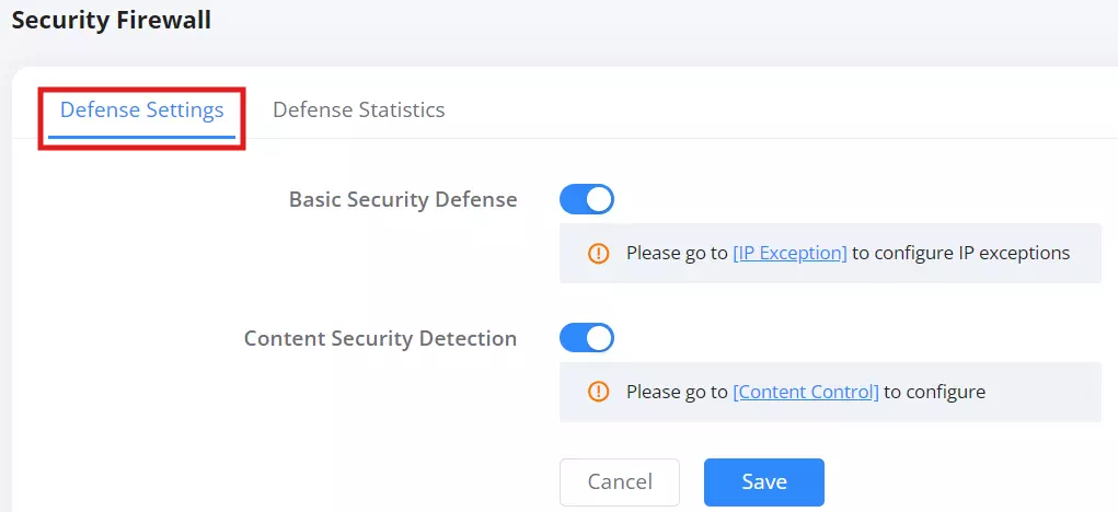
Defense Statistics
The Defense Statistics tab provides real-time data on the router’s security protections.

Key Metrics in Defense Statistics:
- Protection Duration: Displays how long the security system has been actively protecting the network.
- Top Clients: Lists connected clients along with the number of security protections applied.
- Number of Protections in the Last 7 Days: A graphical representation of security events over the past week.
- Details of Protected Events: Displays a log of security events, including source, type, target, and protection time.
Content Control
The Content Control section allows administrators to manage and restrict network access to websites and applications based on predefined filters and categories. This feature is useful for network security, parental controls, and workplace productivity.
To access the Content Control page, navigate to: Security → Content Control

URL Filtering
URL Filtering enables administrators to manually specify websites that should be blocked on the network.
- Click on the “Add” button.
- Enter a Name for the filter rule.
- Specify one or more URLs (e.g.,
www.youtube.com,www.netflix.com). - Click “Save” to apply the rule.
Once added, all clients connected to the network will be restricted from accessing the specified websites.

URL Classification Filtering
This feature provides category-based website filtering, allowing administrators to block or allow predefined groups of websites.
Blocking or Allowing Categories
- Navigate to the URL Classification Filtering tab.
- A list of categories, such as Adult, Phishing, Gambling, Hacking, Cryptojacking, etc., will be displayed.
- To block a category, select “Block” in the action column.
- To allow access to a category, select “Allow”.
This method is efficient for restricting entire categories instead of entering URLs manually.

App Filtering
App Filtering allows administrators to control access to applications based on their category or specific application names.
Blocking or Allowing Applications:
- Navigate to the App Filtering tab.
- A list of categories such as Gaming, Sociality, VoIP, Study, Official, etc., will be displayed.
- Expand a category to view specific applications.
- Choose “Block” or “Allow” for each application or entire category.
This feature is useful for blocking non-work-related applications such as gaming, streaming, or social media.

Blocklist
The Blocklist feature allows administrators to block specific wireless clients from connecting to the network. This is useful for restricting access to unauthorized devices or managing network security.
To access the Blocklist page, navigate to: Security → Blocklist

Adding a Device to the Blocklist:
- Click on the “Add” button.
- Choose a Generation Mode:
- Select from clients – Choose a MAC address from a list of currently connected devices.
- Add Manually – Enter the device’s MAC address manually.
- Select or enter the MAC Address of the client device.
- Click “Save” to block the selected device.
Note: This feature only affects wireless clients. Wired clients will not be blocked.
IP Exception
The IP Exception feature allows administrators to exclude specific IP addresses or ranges from the Basic Security Defense mechanism. This is useful when trusted devices are being incorrectly flagged or blocked by the system’s firewall protections.
Note: The exception only applies to the Basic Security Defense. Other firewall features, such as Content Control or Blocklist, are not affected.
Go to: Advanced → Security → IP Exception
Click the Add button to create a new exception.
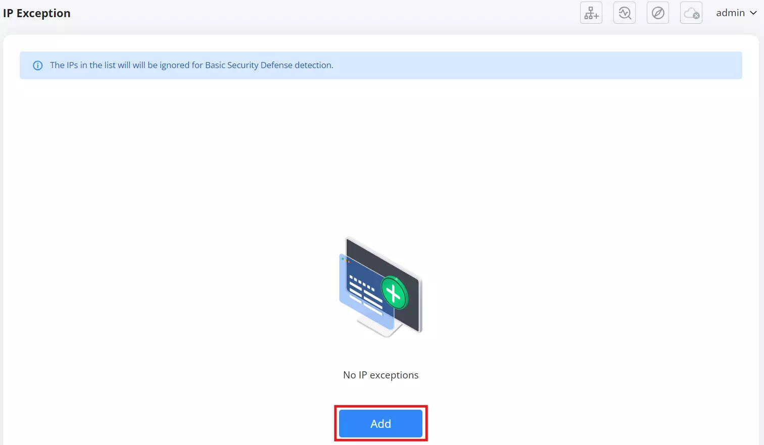
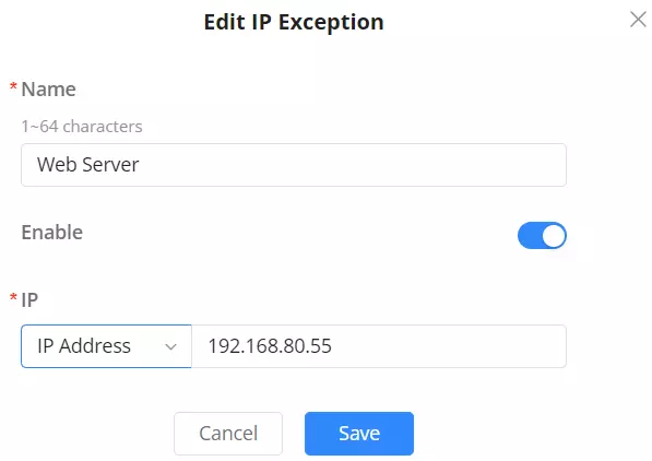
A configuration window will appear with the following options:
- Name: Enter a name to identify the exception rule. (1–64 characters)
- Enable: Use the toggle to activate or deactivate the exception.
- IP:
Choose one of the following from the dropdown:
• IP Address — for a single host (e.g.,192.168.80.55)
• IP Range — for a range of IPs (e.g.,192.168.80.10–192.168.80.30)
• IP Subnet — for subnet-based rules (e.g.,192.168.80.0/24)
Click Save to apply the changes.
Use Cases:
- Exclude your own remote IP to prevent being locked out during testing.
- Allow VPN gateways or management devices through, even when firewall rules are strict.
- Prevent internal monitoring systems from being flagged as threats.
VPN
The VPN section allows users to configure secure communication tunnels between remote networks or clients. The GWN7062M supports up to 8 VPN tunnels simultaneously, and offers multiple VPN protocols suitable for different network environments and security requirements.
To access the settings, navigate to: Advanced → VPN
Supported VPN Protocols:
Upon entering the VPN section, users are presented with a list of supported VPN protocols. Each option is shown with key highlights to help users select the most suitable type:
- WireGuard® (Recommended):
Lightweight and modern protocol with fast performance, small memory usage, and quick configuration. Ideal for mobile devices and dynamic IP environments. - IPSec:
A traditional and highly secure protocol supporting both Client-to-Site and Site-to-Site configurations. Supports automatic rebuild of tunnels in case of WAN IP changes, especially when used with GDMS. - OpenVPN®:
Compatible with a wide range of platforms. Offers certificate-based user and server authentication. Only Client-to-Site mode is available. - PPTP:
Legacy protocol with basic encryption. Only Site-to-Site is supported. Best used for environments where compatibility is more important than security. - L2TP:
Extension of PPTP used by some ISPs. It does not provide encryption by itself. Only Site-to-Site is supported.
Note: Device supports up to 8 VPN tunnels in total across all types.
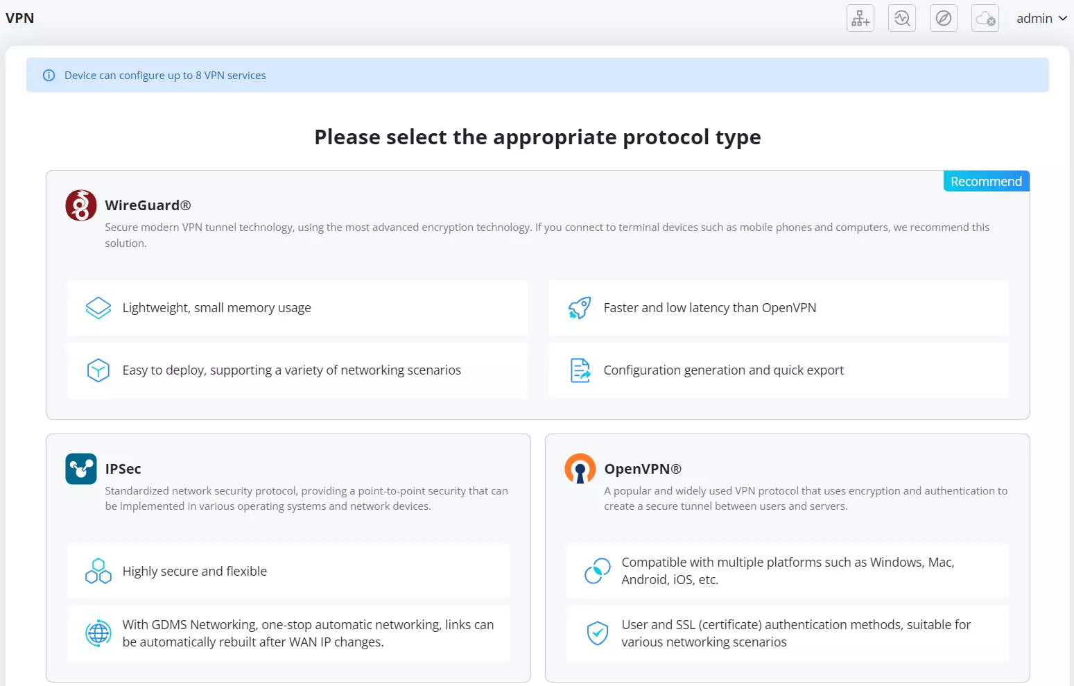
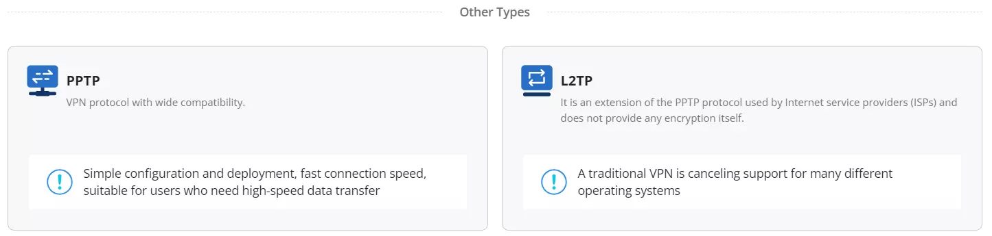
VPN Setup Flow (Per Protocol)
Each protocol has its own configuration workflow:
- WireGuard® Setup Wizard
After selecting WireGuard, users will be prompted to:
- Enter a name for the tunnel.
- Select the WAN interface.
- Set a Monitoring Port (default: 51820).
- Optionally assign forwarding group(s).
- Set Local IP Address and Subnet Mask.
- Generate or input the Private Key. Public Key is auto-generated and can be copied.
WireGuard is suitable for fast deployment scenarios and performs best in environments with limited resources.
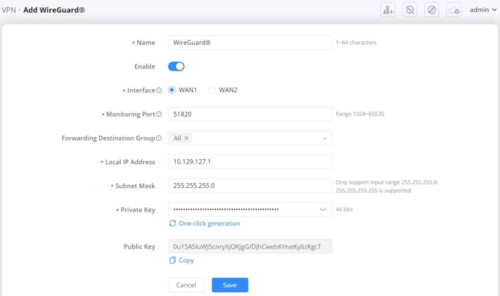
- IPSec Setup Wizard
After selecting IPSec, users must choose the scene:
- Client-to-Site: Remote clients connect to the internal network.
- Site-to-Site: Two sites connect directly via a secure tunnel.
The next steps depend on the selected mode, requiring IP configurations, authentication credentials, and encryption settings.
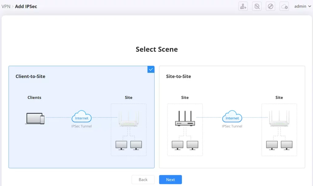
- OpenVPN® Setup Wizard
Only Client-to-Site is available. Configuration includes selecting the tunnel mode, inputting certificates or authentication info, and specifying the client subnet.
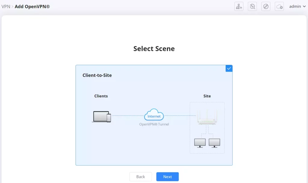
- PPTP and L2TP Setup Wizard
Both protocols only support Site-to-Site mode. After selection, users will configure:
- Remote and local endpoint IPs.
- Authentication credentials.
- Routing settings.
These types are generally used for legacy or simple deployments.
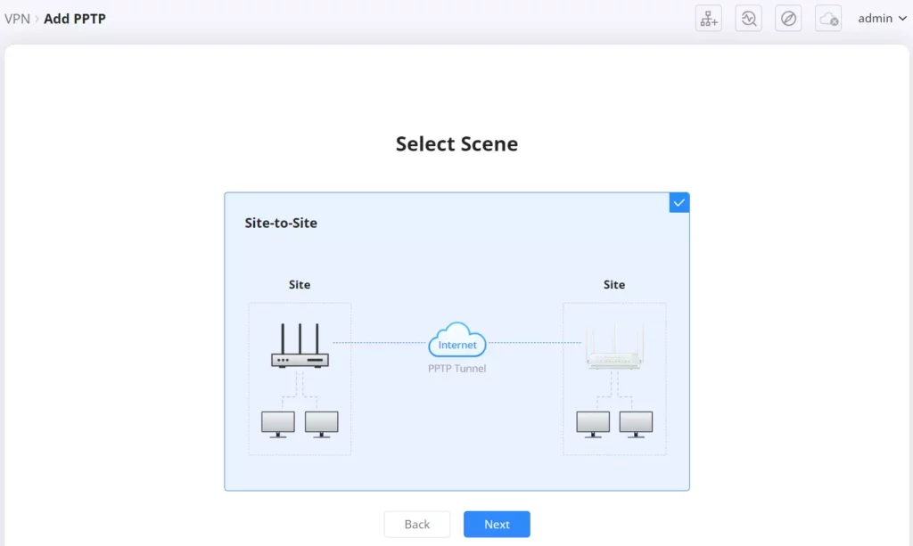
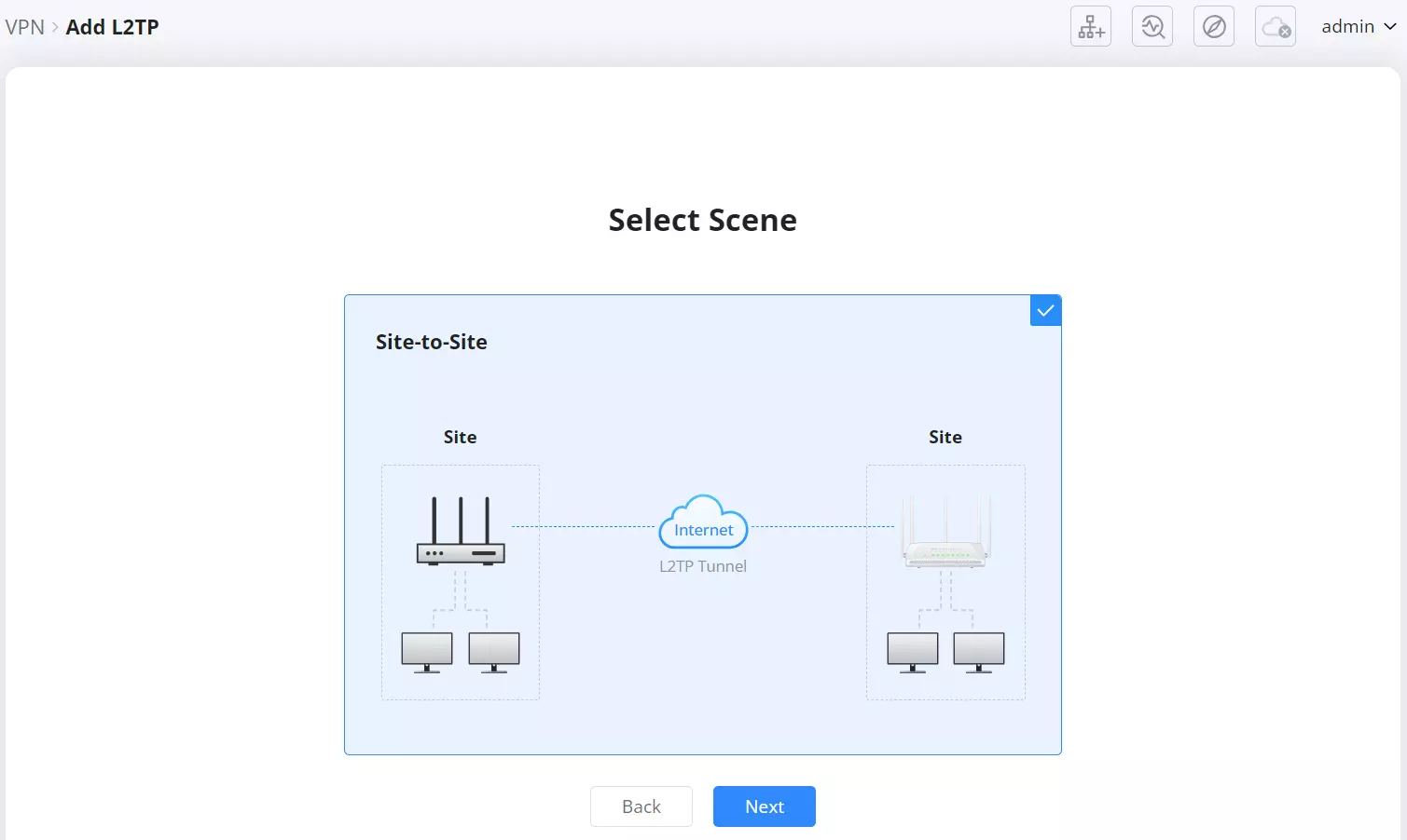
For more details on how to configure VPN, please refer to this guide: VPN Guide
Remote User
The Remote User feature allows administrators to configure and manage individual VPN user accounts that connect to the router using either IPSec or OpenVPN protocols. This is essential for secure remote access to the network.
Users can navigate to: Advanced → VPN → Remote User
Click Add to begin configuration.
Note: This feature is only available on models that support Remote User VPN functionality.
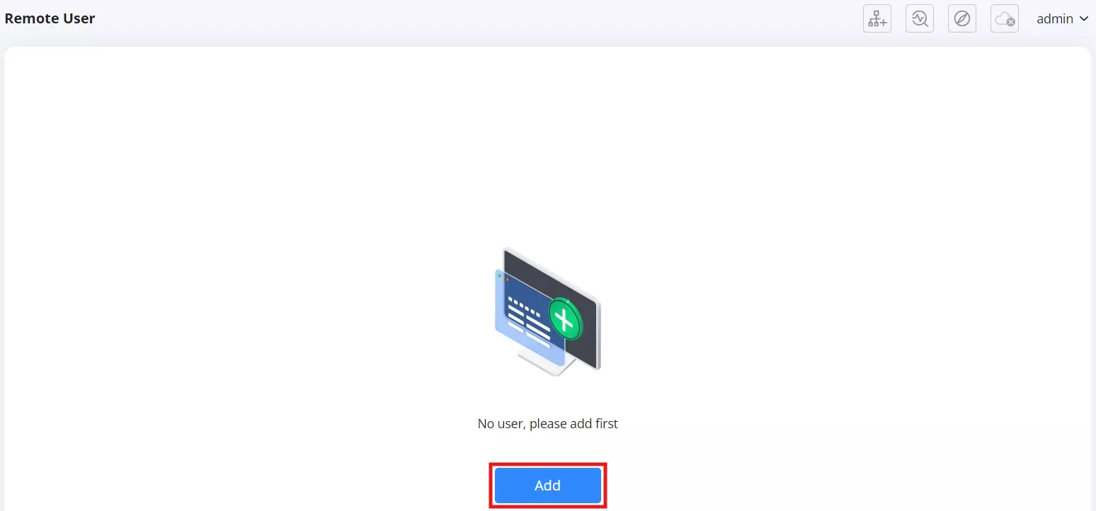
Upon clicking the Add button, a configuration page appears where you can enter details for the new VPN user.
- Name: Enter a unique name for the user (1–64 characters).
- Enable: Toggle to activate or deactivate the account.
- Server Type: Choose between:
- IPSec
- OpenVPN®
IPSec Configuration
If IPSec is selected:
- Server: Select an existing IPSec server configured on the router.
- Dial-in Type:
- IKEv1
- IKEv2
- IPSec XAuth
- Username: Required field (supports 0–64 characters, including
@!$%-_). - Password: Required field (same character support as username).
- IP Address Range: Define a start and end IP address for the remote user tunnel (e.g.,
192.168.90.5 – 192.168.90.9).
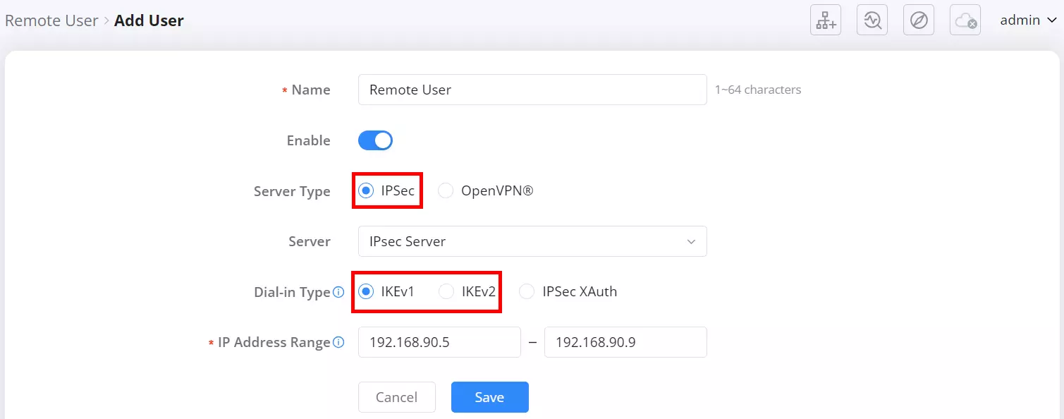
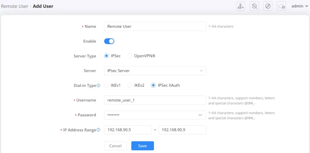
OpenVPN® Configuration
If OpenVPN® is selected:
- Server: Select an existing OpenVPN server from the dropdown.
- Username / Password: Used for authentication.
- Client Subnet: Specify one or more client IP subnets. Click Add to include multiple entries.
- Certificate Type:
- Default Certificate: Uses the router’s default certificate.
- Custom Certificate: Upload and assign a specific certificate file.
- Client Certificate: Required if a custom certificate is selected.
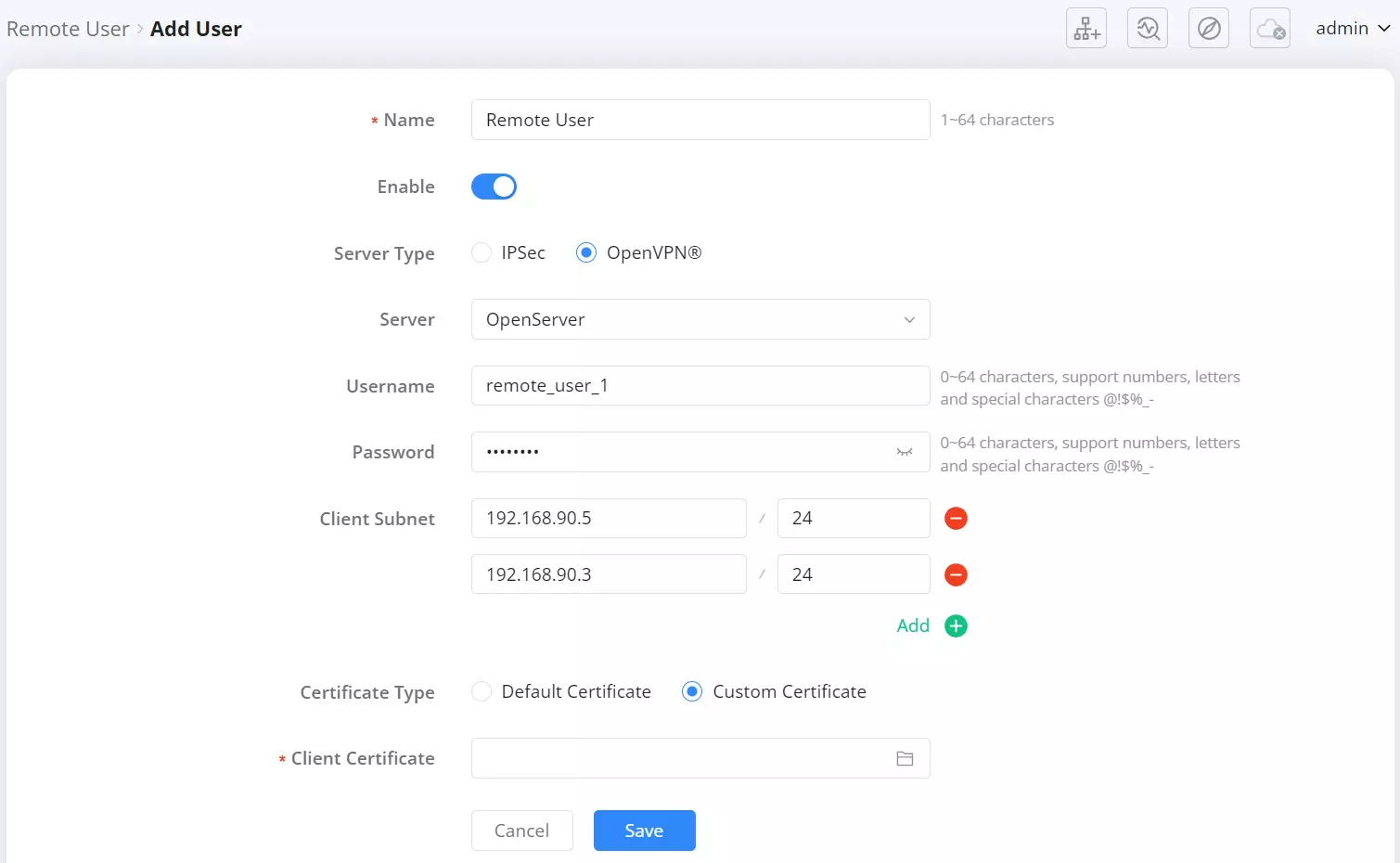
Once all fields are completed, click Save to apply the settings.
IPv6
The router supports IPv6 networking, allowing users to configure WAN and LAN settings for next-generation Internet Protocol connectivity. IPv6 provides a larger address space, improved security, and better support for modern networking needs. The configuration interface for IPv6 is accessible via the router’s web UI under Advanced → IPv6.
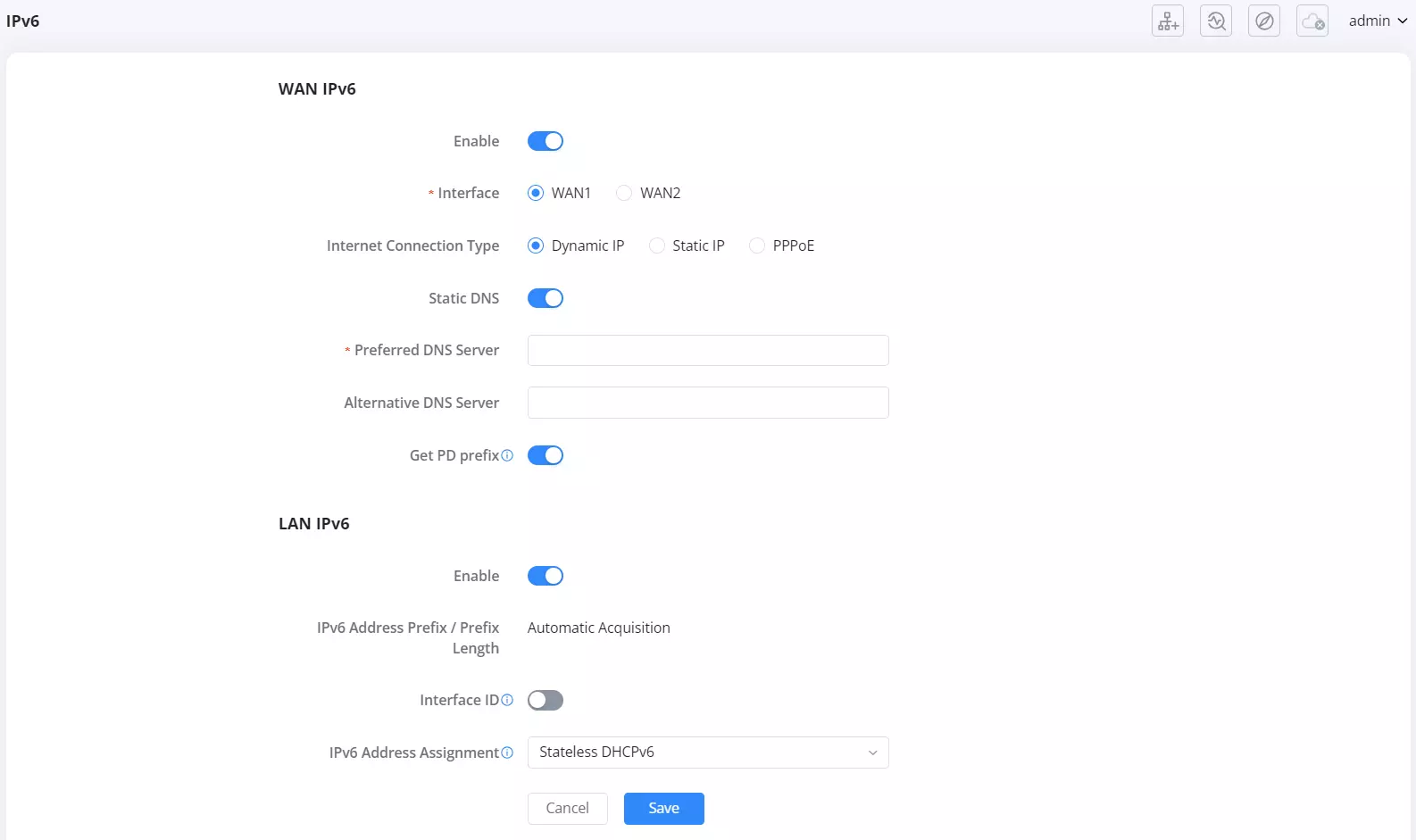
WAN IPv6
This section manages IPv6 connectivity for the WAN interfaces.
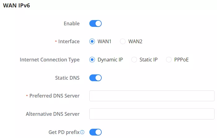
- Enable: Turns on IPv6 support on the selected WAN interface.
- Interface: Select either WAN1 or WAN2 to bind the IPv6 configuration.
- Internet Connection Type:
- Dynamic IP – IPv6 is assigned automatically from the upstream network.
- Static IP – Manually configure the IPv6 address.
- PPPoE – Manually configure PPPoE if required by your ISP for IPv6 access.
- Static DNS: Toggle to manually define IPv6 DNS servers:
- Preferred DNS Server
- Alternative DNS Server
- Get PD prefix: Enable this to request and use a Prefix Delegation (PD) from the ISP, which is often used to assign IPv6 prefixes to the LAN side.
LAN IPv6
This section configures IPv6 behavior within the local network.

- Enable: Enables IPv6 functionality for LAN.
- IPv6 Address Prefix / Prefix Length: Set to Automatic Acquisition or specify manually if needed.
- Interface ID: Toggle to enable interface identifier customization. (Auto-generate IPv6 address when disabled)
- Customize Interface ID: Appears only when the toggle is on.
- IPv6 Address Assignment:
- Stateless DHCPv6
- Stateful DHCPv6
- SLAAC (if available)
This modular approach provides flexibility for both home users and enterprise setups with dual WAN deployments.
Captive Portal
Policy
The Captive Portal Policy feature allows administrators to define access policies for users connecting to the network via a captive portal. These policies can be applied to SSIDs when setting up Wi-Fi access, ensuring that users are prompted with a login or terms acceptance page before gaining internet access.
Located under Advanced → Captive Portal → Policy, this section displays existing captive portal policies and allows the creation of new ones.
To create a new policy, click the “Add” button.

Creating a New Captive Portal Policy:
After clicking “Add”, the configuration page appears with several customizable settings:
- Policy Name: Define a unique name for the captive portal policy.
- Splash Page: Choose between:
- Internal: Uses the built-in splash page.
- External: Redirects users to an external captive portal.
- Client Expiration: Set the duration for which users remain authenticated before requiring re-authentication.
- Client Idle Timeout (Optional): Defines the time (in minutes) after which inactive clients are disconnected.
- Unauthenticated Client Timeout (Optional): Specifies how long an unauthenticated client can remain connected before being disconnected.
- Daily Limit:
- Disable: No limits are applied.
- Limit by client: Restricts access per client.
- Limit by authentication method: Restricts access based on authentication type.
- Splash Page Customization: Select the type of splash page to display.
- Login Page Redirection:
- Redirect to the original URL: After authentication, users are redirected to the page they initially requested.
- Redirect to an external page: After authentication, users are redirected to a specified URL.
- HTTPS Redirection: If enabled, all HTTP traffic will be redirected to HTTPS.
- Secure Portal: Enabling this ensures encrypted connections for the captive portal.
- Pre-Authentication Rules: Allows defining specific IPs or domains that users can access before authentication.
- Post-Authentication Rules: Defines accessible resources after authentication.
Once configured, click “Save” to apply the policy.

Applying a Captive Portal Policy:
After creating a captive portal policy, it can be assigned to an SSID in the Wi-Fi Settings section. Users connecting to this SSID will be required to authenticate via the defined captive portal policy before accessing the network.
This feature helps administrators enforce security and access controls effectively, ensuring compliance with network policies.
Splash Page
The Splash Page is a customizable web-based login interface that appears when users connect to a Wi-Fi network using a Captive Portal Policy. This page is used for authentication and can be configured with different login methods.
Go to Advanced → Captive Portal → Splash Page in the router’s Web UI.

Splash Page Components:
When adding a splash page, users can customize various elements, including:
- Basic Components
- Image: Upload a custom logo or branding.
- Text: Display a welcome message.
- Terms of Use: Optionally require users to accept terms before accessing the network.
- Login Components
- For Free: Allows open access without authentication.
- Simple Password: Users enter a pre-configured password.
- Facebook Login: Authenticate using a Facebook account.
- X (formerly Twitter) Login: Authenticate using an X (Twitter) account.
- Google Login: Authenticate using a Google account.
- Voucher Login: Users enter a generated voucher code.
Customization Options:
- Button Text & Colors: Customize login button text, colors, and styles.
- HTTPS Redirection: Enable/disable HTTPS redirection for security.
- Secure Portal: Enhances security for the login page.

Using Splash Page with Captive Portal Policy:
Once created, a splash page can be assigned to a Captive Portal Policy, which is then linked to an SSID in Wi-Fi Settings. This ensures that users connecting to the Wi-Fi network will be redirected to the splash page for authentication.
Guests
The Guests Page provides an overview of all users who have connected to the network using a Captive Portal Policy. This page displays authentication details for clients who accessed Wi-Fi SSIDs configured with a captive portal.
Navigating to the Guests Page:
- Go to Advanced → Captive Portal → Guests in the router’s Web UI.

Guest Information Displayed:
The Guests Page lists details of connected clients, including:
- Client: The device name and MAC address.
- Wi-Fi Name: The SSID (Wi-Fi network) the client connected to.
- Authentication Type: The method used to authenticate (e.g., “For Free,” “Simple Password,” “Facebook,” etc.).
- Login Time: The timestamp when the client successfully authenticated.
- End Time: The expiration time of the authentication session.
- Authentication Status: Indicates whether the client is currently authenticated or not.
Filtering and Managing Guests:
- Use the search bar to filter guests by Wi-Fi SSID or Client Name/MAC Address.
- Click the Trash Bin icon under “Operations” to remove or disconnect a guest from the network.
Use Case:
This page is useful for administrators to:
- Monitor guest connections in real-time.
- Manage authentication sessions for different users.
- Identify and troubleshoot access issues.
Vouchers
The Vouchers feature is part of the Captive Portal system. Vouchers allow administrators to generate access codes that can be distributed to users for temporary or controlled internet access. These vouchers can be linked to a Splash Page, which in turn is applied to a Captive Portal Policy and assigned to a Wi-Fi SSID.
Navigating to the Vouchers Page:
To configure vouchers, go to: Advanced → Captive Portal → Vouchers
This page displays the list of generated voucher groups and provides options to create, manage, and distribute them.

Adding a Voucher Group:
To create a new voucher group:
- Click the Add button on the Vouchers page.
- Fill in the required details:
- Voucher Group Name: A label to identify the voucher group.
- Quantity: Number of vouchers to generate (1-100).
- Max Devices: Maximum number of devices per voucher (1-5).
- Byte Limit: Set a data limit per voucher or per device (MB/GB).
- Traffic Allocation Method:
- Per Voucher: The total data limit applies to all devices using the same voucher.
- Per Device: Each device gets an independent data limit.
- Duration: Defines how long the voucher remains active (days/hours/minutes).
- Valid Time: The period before the voucher expires (1-365 days).
- Description: Optional text to describe the voucher usage.
- Click Save to generate the vouchers.

Managing Vouchers:
Once created, the voucher group will be listed on the Vouchers page. Each entry includes:
- Voucher Quota: Displays used vs. available vouchers.
- Duration: The validity period of the vouchers.
- Byte Limit: The data allocation per voucher.
- Created Time & Expiry Time: When the vouchers were generated and when they will expire.
- Description: Notes about the voucher group.
Operations Available:
- View Details: Inspect voucher details.
- Print: Generate a printable voucher list.
- Download: Export voucher details as a file.
- Delete: Remove a voucher group.

Using Vouchers in Captive Portal:
- When creating a Splash Page, enable the Voucher Login option.
- Assign the splash page to a Captive Portal Policy.
- Apply the policy to a Wi-Fi SSID.
- Users connecting to the SSID will be prompted to enter a valid voucher code for authentication.
USB Application
USB Dongle
The USB Dongle page is used to detect whether a supported USB dongle is connected to the GWN7062M and to display basic dongle/SIM status. This page is intended for detection and status verification. Internet access configuration using the dongle (USB WAN) is configured elsewhere.
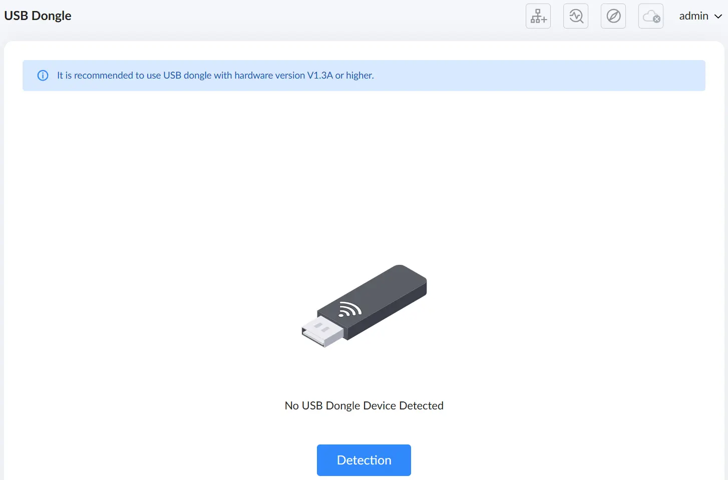
When no dongle is connected, or the device is not recognized, the page displays No USB Dongle Device Detected. Click Detection to scan for a connected dongle.
Important notes:
- USB dongle detection is supported on the primary router (main unit).
- This page is for detection/status only. To use the dongle as an internet uplink, configure USB WAN under Advanced → Internet Settings → Internet Settings. USB WAN options are displayed only after the dongle is inserted and detected.
To verify operation quickly, the practical flow is: connect the dongle to the primary router → open USB Dongle → click Detection → confirm the dongle and SIM status are shown → then proceed to USB WAN configuration if an internet uplink is required.
Network Printer (Beta)
The Network Printer feature allows the GWN7062M to detect a USB printer and share it with users on the network. Availability depends on the printer being physically connected to the router.
Printer Status
The Printer Status tab is used to detect and display connected USB printers. Click Detection to scan for a connected printer. When a printer is detected, it appears in the list under the primary router, showing the printer model (for example, HP LaserJet Professional P1106).
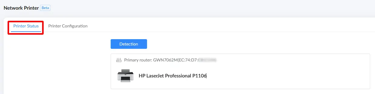
Printer Configuration
The Printer Configuration tab is used to enable network printing and define how clients access the shared printer. Network printing is only available when a printer is connected, and the network printing function works only after connecting a printer to the selected device node.
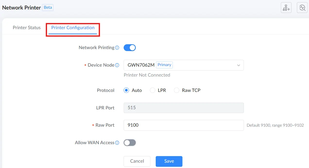
The following table describes the available settings.
| Setting | Description |
|---|---|
| Network Printing | Enables or disables the network printer sharing service. Network printing is only available when a printer is connected. |
| Device Node | Selects the device node to which the printer is connected. Network printing works only after connecting a printer to the selected device node. |
| Protocol | Selects the printing protocol used by clients. Available options: Auto, LPR, and Raw TCP. |
| LPR Port | Sets the LPR port used when LPR is selected. The default value is 515. |
| Raw Port | Sets the port used when Raw TCP is selected. The default value is 9100 (range 9100–9102). |
| Allow WAN Access | Allows devices on the internet to access the printer using the WAN IP address or domain name. Enabling this option exposes the printer to the internet and may increase security risks. |
When enabling Allow WAN Access, the system displays a warning message indicating that the printer may be exposed to the internet, with potential risks such as attacks and data leaks.
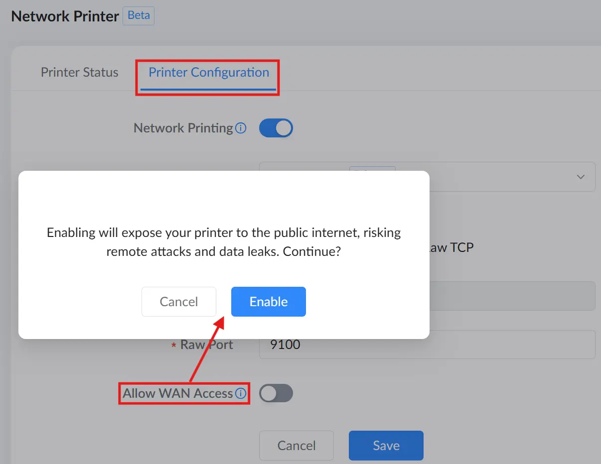
Security note: Enabling WAN access makes the printer reachable from outside the local network. Only enable this option when necessary, and ensure appropriate security controls are in place.
Network Sharing Service
The Network Sharing Service feature allows the GWN7062M to detect a USB storage device and share it over the network using Samba (SMB). It also provides user management to control who can access the shared storage and what permissions they have.
Storage Device Status
The Storage Device Status tab is used to detect and display connected USB storage devices. Click Detection to scan for a connected storage device. When a storage device is detected, the page displays its status and basic information such as storage capacity, file system format, and the currently connected user.
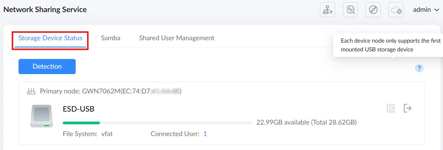
Important note: Each device node only supports the first mounted USB storage device. If multiple USB storage devices are mounted on the same node, only the first mounted device can be used by the sharing service.
Samba
The Samba tab is used to enable SMB file sharing and provides the access links that clients can use to reach the shared storage.
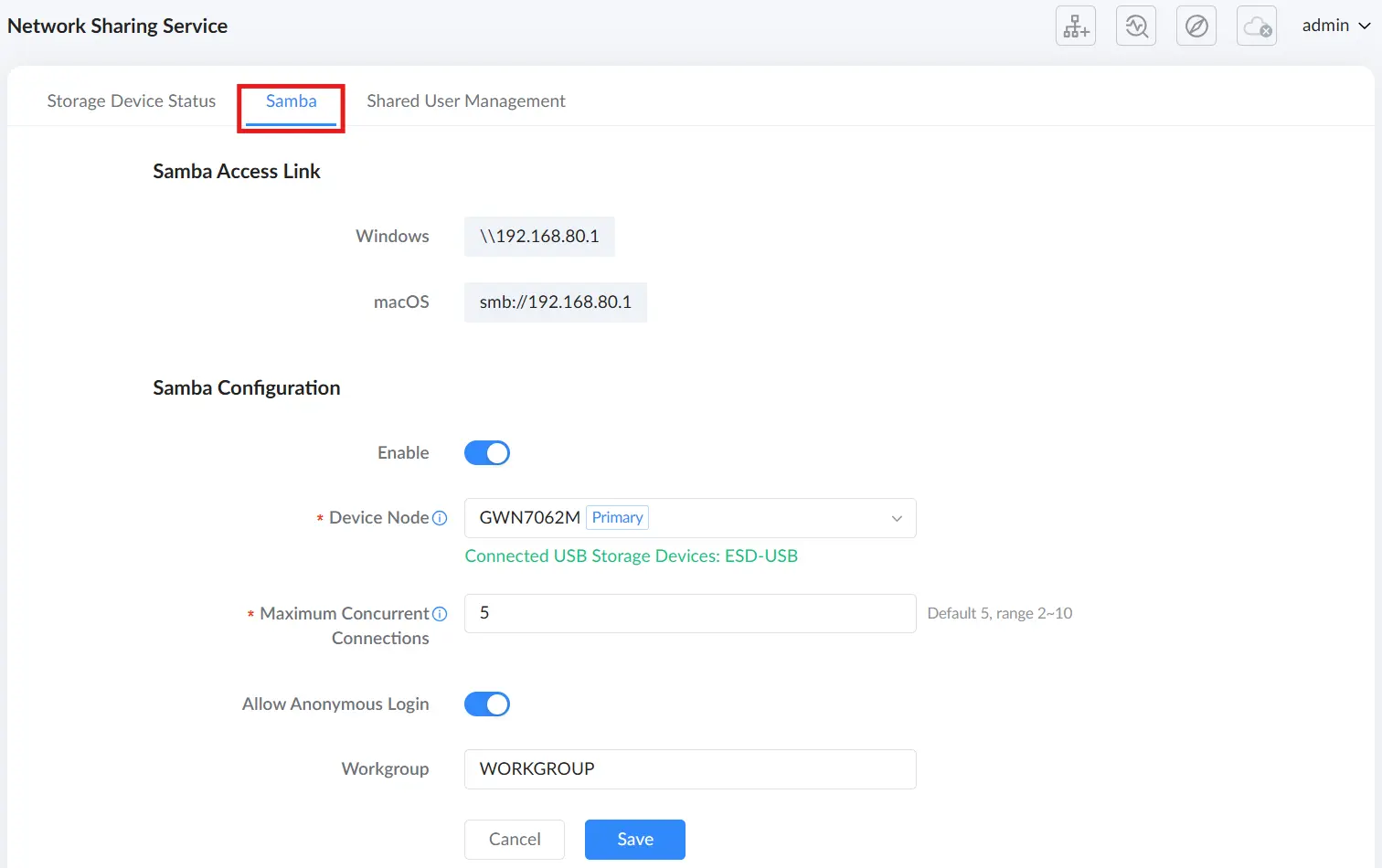
The Samba Access Link section displays OS-specific access paths after Samba is enabled:
- Windows:
\\192.168.80.1 - macOS:
smb://192.168.80.1
The Samba Configuration section includes the following settings.
| Setting | Description |
|---|---|
| Enable | Enables or disables Samba (SMB) file sharing for the connected USB storage device. |
| Device Node | Selects the device node to which the USB storage device is connected. Shared services only work after connecting a storage device to the selected device node. |
| Maximum Concurrent Connections | Sets the maximum number of concurrent Samba connections to the USB storage device. When the maximum is reached, additional users cannot connect. Default is 5, range 2–10. |
| Allow Anonymous Login | Allows clients to access the shared storage without authentication. Use with caution in environments where access control is required. |
| Work Group | Sets the SMB workgroup name used for Windows network discovery (default is WORKGROUP). |
Shared User Management
The Shared User Management tab is used to create and manage users who can access the shared USB storage device. Users can be enabled/disabled, assigned permissions, and edited or deleted.
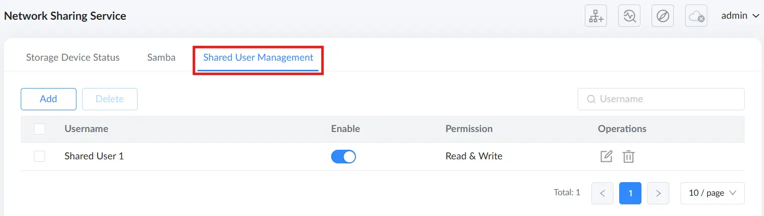
To add a new shared user, click Add, configure the user details, and click Save.
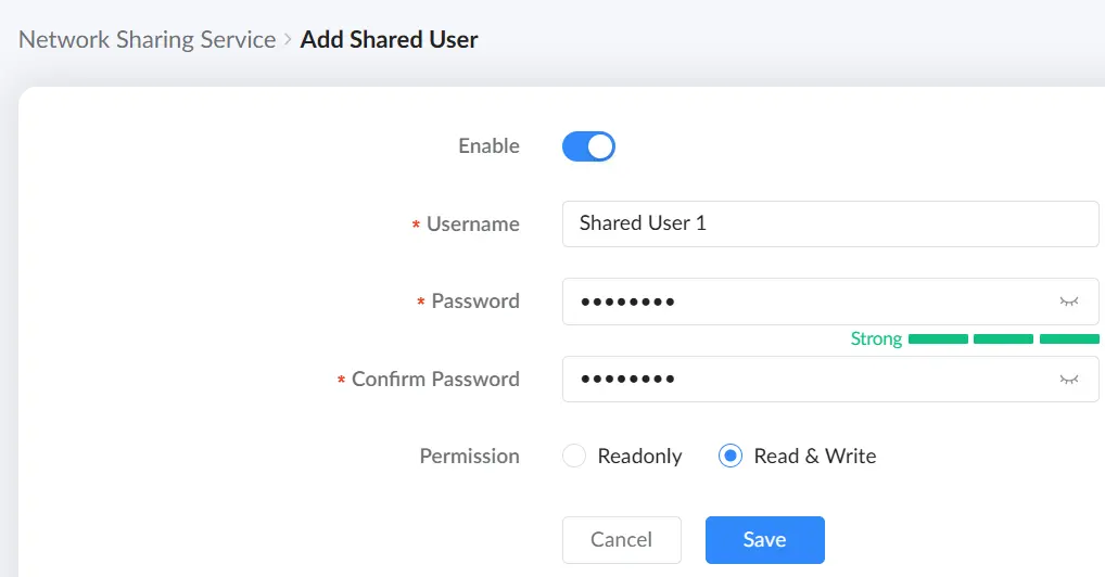
The following options are available when adding a shared user.
| Setting | Description |
|---|---|
| Enable | Enables or disables the shared user account. |
| Username | Sets the username used to authenticate when accessing the shared storage. |
| Password / Confirm Password | Sets the password for the shared user account. The UI displays a password strength indicator. |
| Permission | Defines the access level granted to the user. Available options: Readonly or Read & Write. |
Accessing the Shared Storage
After enabling Samba and connecting a USB storage device, users can access the shared storage from their client devices.
For Windows clients, open File Explorer and access the router using the Windows Samba path (for example, \\192.168.80.1). The shared storage appears as a folder that can be opened to browse files.
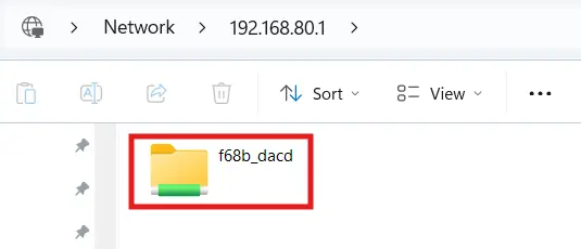
Maintenance
Upgrade
The Upgrade section in the router web UI allows users to update the router’s firmware to the latest version. Firmware updates provide security patches, performance enhancements, and new features, ensuring the router remains up to date and functions optimally.
To access the Upgrade page:
- Log in to the router’s web UI.
- Navigate to Maintenance → Upgrade in the left menu.
- The upgrade section will display details about the current firmware version and update options.
Steps for Manual Upgrade:
- Select the Node Router:
- Choose either:
- Primary router (GWN7062M)
- Sub-router (GWN7062ET) (if part of a mesh network)
- Choose either:
- Upload the Firmware File:
- Click Upload to select the firmware file.
- Ensure the file is in
.binformat.
- Click Upgrade to start the firmware update process.
Note: Do not power off or disconnect the router during the update process.
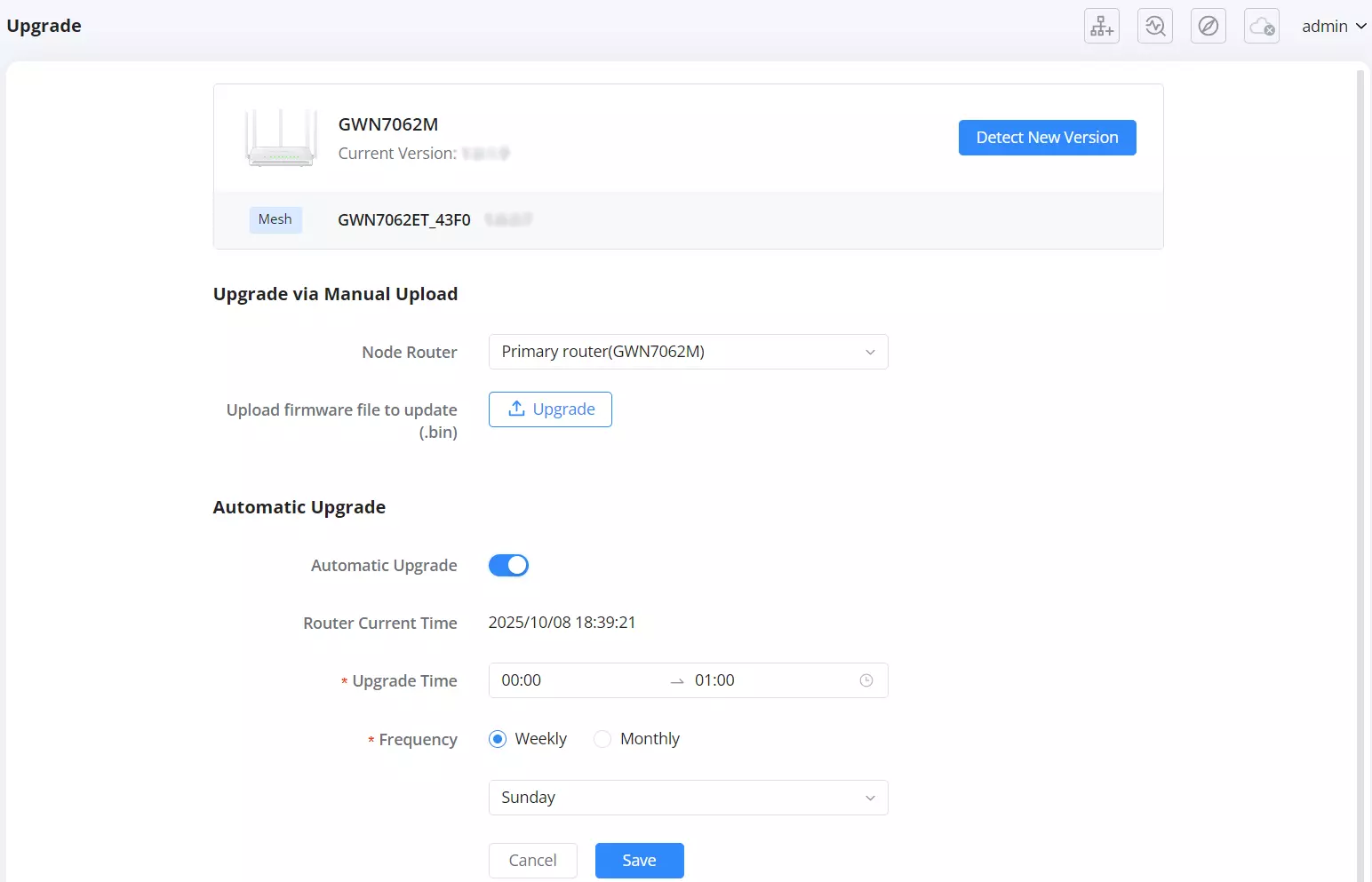
Steps to Enable Automatic Upgrade:
- Toggle ON the Automatic Upgrade option.
- Set Upgrade Time – Define the time range for the update.
- Choose Frequency:
- Weekly – Select the day of the week (e.g., Sunday).
- Monthly – Choose a specific day of the month.
- Click Save to apply the settings.
Benefits of Automatic Upgrade:
- Ensures the router stays up to date without manual intervention.
- Reduces downtime by scheduling updates during non-peak hours.
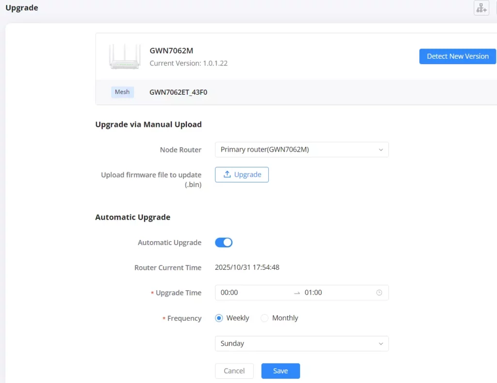
Backup & Restore
The Backup & Restore section in the router allows users to save, restore, and reset the router’s configuration. This feature ensures that users can preserve their network settings, recover from misconfigurations, and restore factory defaults when necessary.
To access Backup & Restore:
- Log in to the router’s web UI.
- Navigate to Maintenance → Backup & Restore in the left menu.
- The page will display options to Export, Import, or Factory Reset the configuration.

- The Backup function allows users to save the current router configuration to a local computer or a USB device.
Note: For security and operational purposes, please be aware that the backup .bin file does not include the following settings. These will need to be reconfigured manually if the device is restored:
- Mesh Network Configurations: Any configured Mesh network settings are excluded. Consequently, sections in the user interface that display Mesh nodes (such as the Network Map) will appear empty until the Mesh network is reconfigured.
- Captive Portal Vouchers: All generated vouchers used for Captive Portal authentication will not be saved.
- TR-069 Credentials: The connection request username, password, and port settings used for TR-069 remote management are excluded.
- GWN Manager Settings: The cloud management access settings (Manager Settings) are not retained in the backup file.
- Maintenance Tunnel: Any active maintenance tunnel configurations used for remote diagnostics will not be backed up.
Steps to Backup Configuration:
- Click the Export button.
- The router will generate a backup file (.bin) containing the current configuration.
- Save the file to your computer or an external storage device.
Use Case:
- Before making significant changes to the router settings.
- For disaster recovery, allowing quick restoration of network settings.
- To replicate configurations across multiple routers.
- The Restore function allows users to reload a previously saved configuration file.
Steps to Restore Configuration:
- Click the Import button.
- Select the previously saved backup file (.bin) from your computer.
- The router will load the configuration and apply the settings.
Important Notes:
- Restoring a backup overwrites the existing configuration.
- If a restore fails and the router becomes unresponsive, press and hold the physical reset button on the router for 5 seconds to restore factory settings.
- The Factory Reset function resets the router to its default settings, erasing all user configurations.
Steps to Perform a Factory Reset:
- Click the Factory Reset button.
- Confirm the action when prompted.
- The router will reboot and revert to its original settings.
Alternative Reset Method:
- Press and hold the reset button on the back of the router for 5 seconds until the LED indicator blinks.
- The router will reset and restart with factory defaults.
Caution:
- All settings will be lost after a factory reset.
- It is highly recommended to perform a backup before resetting the router.
Diagnostics
The Diagnostics section in the router web UI provides essential troubleshooting tools to monitor system events, diagnose network issues, and capture logs. These tools help administrators identify potential problems, analyze network performance, and perform debugging tasks efficiently.
To access Diagnostics:
- Log in to the router’s web UI.
- Navigate to Maintenance → Diagnostics in the left menu.
- Select the relevant tab to perform diagnostic actions.
1. Log Monitoring
The Log tab records and displays system and network activity logs.
Features:
- Time – Timestamp of logged events.
- Severity – Indicates event type (Notice, Warning, Error).
- Platform – Identifies whether the log event is local or network-related.
- Address – Shows the IP address involved in the event.
- Log Type – Categorizes log entries (Operation, Configuration, Security, etc.).
- Details – Provides additional information about the event.
Exporting Logs:
- Click Export to download logs as a CSV file for offline analysis.
Use Case:
- Monitor configuration changes, remote access attempts, and security alerts.
- Identify network connectivity issues and troubleshoot them effectively.
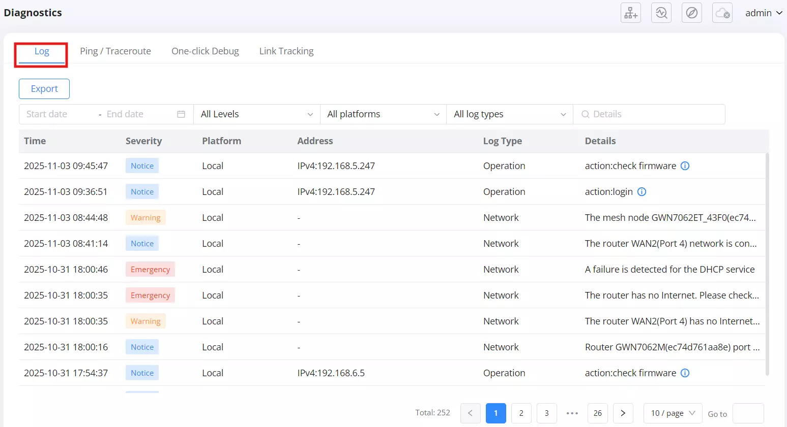
2. Ping / Traceroute
This tool helps verify network connectivity and diagnose latency or packet loss.
Steps to Use Ping / Traceroute:
- Select Diagnostic Tools:
- Ping (IPv4/IPv6) – Checks if a device is reachable.
- Traceroute – Traces the path packets take to a destination.
- Enter Target IP Address / Hostname.
- Select Interface (Auto by default).
- Click Start to run the test.
Results Interpretation:
- Low latency & no packet loss → Connection is stable.
- High latency or packet loss → Possible network congestion or faulty routing.
Use Case:
- Verify Internet connectivity to external sites (e.g., 1.1.1.1).
- Diagnose delays and packet loss in internal or external network paths.
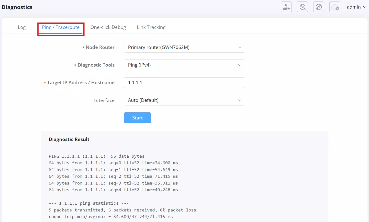
3. One-click Debug
This feature automatically collects system logs and diagnostic data in a compressed file.
Steps to Generate Debug File:
- Click Redebug to start data collection.
- Once completed, a debugging result file appears.
- Click the download icon to save the debug file.
Use Case:
- Share the debug file with technical support for advanced troubleshooting.
- Identify firmware issues, network crashes, or system failures.
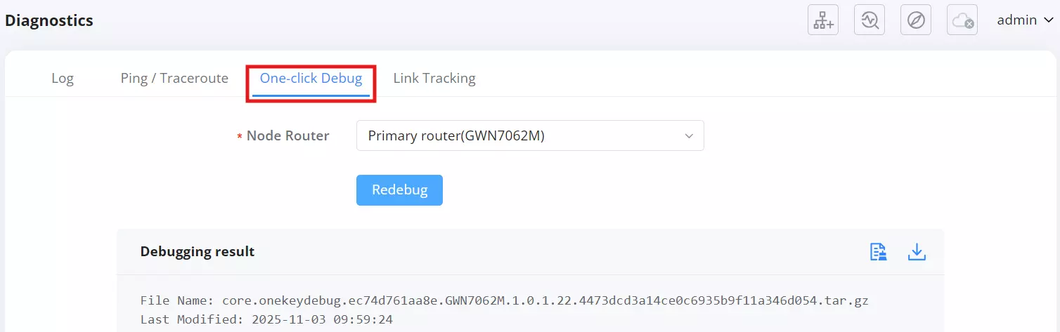
4. Link Tracking
Monitors and controls network connection limits.
Configuration:
- Link Tracking Upper Limit – Adjusts the maximum number of tracked links.
- Default limit: 16384 (adjustable up to 32768).
Use Case:
- Helps optimize bandwidth monitoring.
- Prevents excessive logging overload.
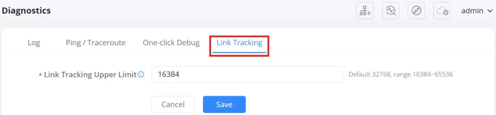
Intelligent Detection
The Intelligent Detection feature in the router helps users diagnose and troubleshoot various network and system performance issues. This tool provides a comprehensive analysis of security, connectivity, internet failures, and mesh node connections, ensuring optimal router performance.
To access Intelligent Detection:
- Log in to the router’s web UI.
- Navigate to Maintenance → Intelligent Detection.
- Select the relevant tab to perform detection tests.
1. Detection Tab
The Detection tab provides a complete network security and performance check.
How to Run a Detection Test:
- Click the Detection button.
- The router runs diagnostics on the following areas:
- Security Protection – Checks for firmware updates, firewall settings, and Wi-Fi security.
- Network Connectivity – Analyzes DNS latency and packet loss.
- Connection Rate – Monitors the status of network ports.
- Signal Quality – Evaluates the Wi-Fi channel quality.
- Once completed, the test results display a rating (e.g., Poor, Good, Excellent).
- Click Redetect to run the test again.

Use Case:
- Quickly assess network security and connectivity.
- Detect issues such as outdated firmware, firewall misconfigurations, or packet loss.

2. Management Platform Connection Status
This tab tests the router’s connection with the Grandstream Device Management System (GDMS).
How to Run a Connection Detection Test:
- Click Detection to start the connection test.
- The system verifies different connection phases:
- Preparation Phase
- Domain Name Resolution Phase
- TCP Connection Phase
- TLS Connection Phase
- HTTPS Transaction Phase
- WebSocket Upgrade Phase
- If all phases are successful, the connection is stable.

Use Case:
- Ensures the router can connect to GDMS for remote management and monitoring.
- Identifies issues preventing the router from establishing a secure GDMS connection.

3. Internet Failure Detection
This tab diagnoses network failures for WAN (Internet) and Client Devices.
Running a WAN Connection Test:
- Select WAN and choose the desired interface (WAN1 / WAN2).
- Click Start.
- The test checks for:
- IPv4 connectivity.
- IPv6 service availability.
- DNS response times.
Example Issue: If IPv6 is disabled, the test will prompt the user to check IPv6 settings.

Running a Client Connection Test:
- Select Client and choose a connected device from the list or enter a MAC address manually.
- Click Start.
- The system verifies:
- If the client device has been active in the last 30 minutes.
- If the device is experiencing connectivity issues.
Example Issue: If a client has no connection logs, it may indicate a disconnect or network problem.
Use Case:
- Detects Internet connectivity failures in WAN/LAN.
- Troubleshot client device disconnections.

4. Mesh Node Connection
This tab checks the status of connected mesh nodes in a multi-router setup.
Running a Mesh Node Detection Test:
- Click Detect.
- The router scans for all connected mesh nodes.
- Results display:
- Mesh node device name.
- Signal strength.
- Connection status (Connected/Disconnected).
Use Case:
- Ensures mesh nodes are properly connected.
- Troubleshot mesh coverage issues.

TR-069
TR-069 (Technical Report 069) is a protocol for remote management of network devices, including routers. It allows Auto-Configuration Servers (ACS) to remotely configure, update firmware, monitor performance, and troubleshoot network devices without requiring manual intervention. This feature is commonly used by ISPs and IT administrators to manage a large number of routers remotely.

TR-069 Configuration Options:
1. Enabling TR-069
- TR-069 Toggle – Enables or disables the TR-069 remote management feature.
2. Auto-Configuration Server (ACS) Settings
- ACS URL – The URL of the Auto-Configuration Server (ACS) that manages the router.
- ACS Username & Password – The credentials used by the ACS to authenticate and communicate with the router.
3. Periodic Inform
- Periodic Inform Toggle – When enabled, the router will periodically send status updates to the ACS.
- Periodic Inform Interval (sec) – Defines how frequently (in seconds) the router should send inform messages to the ACS. The default is 86400 seconds (24 hours).
4. Connection Request Settings
- Connection Request Username & Password – Credentials required for the ACS to initiate a request to the router.
- Connection Request Port – Defines the port used for ACS requests. The default is 7547 (configurable between 1-65535).
5. Certificate Authentication
- CPE Cert File – Upload a certificate file to enable encrypted authentication between the router and ACS.
- CPE Cert Key – Upload a private key to establish a secure connection.
Use Cases for TR-069:
- Remote Configuration – Allows ISPs and administrators to configure settings remotely.
- Firmware Management – Enables automated firmware updates without user intervention.
- Monitoring & Diagnostics – Collects real-time router performance data for troubleshooting.
- Security & Compliance – Ensures routers follow security policies through automated management.
System
Basic Settings – System
The Basic Settings section in the router web UI allows users to configure fundamental system settings such as time synchronization, language preferences, LED status, and automatic reboot scheduling. These settings help in ensuring accurate timekeeping, maintaining optimal device behavior, and improving overall network management.
To access the Basic Settings:
- Log in to the router’s web UI.
- Navigate to System → Basic Settings in the left menu.
- The page will display options to configure system settings as described below.

Basic Settings Options:
Device Current Time
- Displays the current system time of the router.
- This time is determined by the configured time zone and NTP server settings.
Country/Region
- Allows users to select the country or region where the router is deployed.
- This setting helps adjust time zone and regulatory compliance settings accordingly.
Time Zone
- Select the correct UTC offset from the dropdown menu.
- Ensures proper time synchronization for logs, scheduling, and other time-dependent services.
NTP Server
- The Network Time Protocol (NTP) Server synchronizes the router’s time automatically.
- Users can specify one or more NTP servers (e.g.,
0.pool.ntp.org,1.pool.ntp.org). - Clicking the Add (+) button allows additional NTP servers to be added.
Language
- Allows users to select the interface language.
- The default setting is English.
LED Indicator Settings
- Always On – The router’s LED indicators remain active at all times.
- Always Off – The LED indicators are completely disabled.
- Disabled within the specified time – The LEDs will be turned off during a specified time period to reduce light pollution.
Reboot Schedule
This feature allows users to automatically reboot the router at a scheduled time, ensuring optimal performance by clearing temporary data and refreshing system processes.
- Enable/Disable Toggle – Users can enable or disable the scheduled reboot.
- Reboot Time – Defines the time frame for the scheduled reboot.
- Frequency:
- Weekly – The router will reboot on a selected day of the week.
- Monthly – The router will reboot on a specific day of the month.
- Day Selection – If Weekly is selected, users can choose the day (e.g., Sunday).
Access Management
The Access Management section of the router allows users to configure authentication, user accounts, remote access control, and security policies to protect and manage administrative access. These settings enhance security by enforcing strong password policies, restricting unauthorized access, and enabling remote management through secure protocols.
To access Access Management settings:
- Log in to the router’s web UI.
- Navigate to System → Access Management in the left menu.
- Select the relevant tab to configure access settings.
Admin Password
The Admin Password tab allows administrators to change the default password for security purposes.
Options:
- Old Password – Enter the current admin password.
- New Password – Set a new password (must be 8-64 characters long).
- Confirm New Password – Re-enter the new password for confirmation.
Best Practices:
- Use a strong password with a mix of uppercase letters, numbers, and symbols.
- Change the default password immediately after setup for security.
- Regularly update passwords to reduce security risks.

User Account
The User Account tab allows the creation of a secondary user account with limited access.
Options:
- Enable – Toggle to enable or disable the user account.
- User Password – Set a password for the secondary user.
- Confirm User Password – Re-enter the password to confirm.
Key Notes:
- Once enabled, the user can log in using the username “user”.
- This account has restricted privileges compared to the administrator.
- Useful for allowing network monitoring without granting full access.

Access Control
The Access Control tab manages administrative access to the router from the LAN and WAN.
LAN Side Settings:
- HostName – Displays the router’s local domain name.
- HTTPS Port – Default is 443 (Range: 1-65535).
WAN Side Settings:
- Access through WAN – Toggle to enable remote access over the Internet.
- HTTPS Port – Specifies the port for remote HTTPS access.
- IP Addresses Allowed to be Accessed – Restrict remote access to specific IP addresses. (Note: if left empty, all IP Addresses are allowed.)
Security Recommendations:
- Disable WAN access if remote management is unnecessary.
- Change the default SSH/HTTPS ports to reduce attack risks.
- Restrict remote access to specific IPs whenever possible.
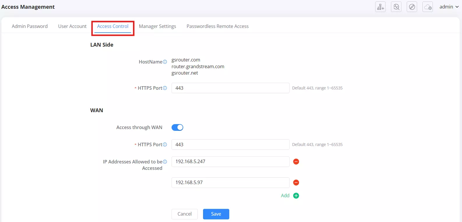
Manager Settings
This tab allows remote management through GWN Manager, Grandstream’s on-premise network management platform.
Options:
- Allow DHCP Option 43 to Override Manager Server Address – When enabled, DHCP Option 43 can override the predefined GWN Manager address.
- Manage Server Address – Enter the IP or domain of the GWN Manager server.
- Manage Server Port – Default is 8443.

Passwordless Remote Access
This feature allows remote access without requiring a password when using GDMS Networking, Grandstream’s cloud management platform.
Options:
- Passwordless Access Toggle – Enable or disable passwordless login.
Security Considerations:
- Enable this feature only if using GDMS Networking for remote access.
- If security is a concern, it’s best to disable passwordless access and require authentication.

Operation Mode
The router supports three different working modes under the System → Working Mode section, allowing users to deploy the router in various network environments based on their needs:
- Router Mode (Default)
- Wireless Relay Mode
- Wireless Bridge Mode
Each mode affects how the device connects to the upstream network and handles LAN traffic—whether it’s routing traffic, rebroadcasting existing Wi-Fi, or serving as a wireless bridge to wired devices.
- Router Mode
This is the default mode. The device connects directly to the Internet via DHCP, PPPoE, PPTP, L2TP, or Static IP, then shares that connection with local clients either through Ethernet or Wi-Fi. Users can also add Mesh sub-nodes for broader coverage.
Usage Example:
Standard internet access with full routing and NAT capabilities. Ideal for homes and offices.
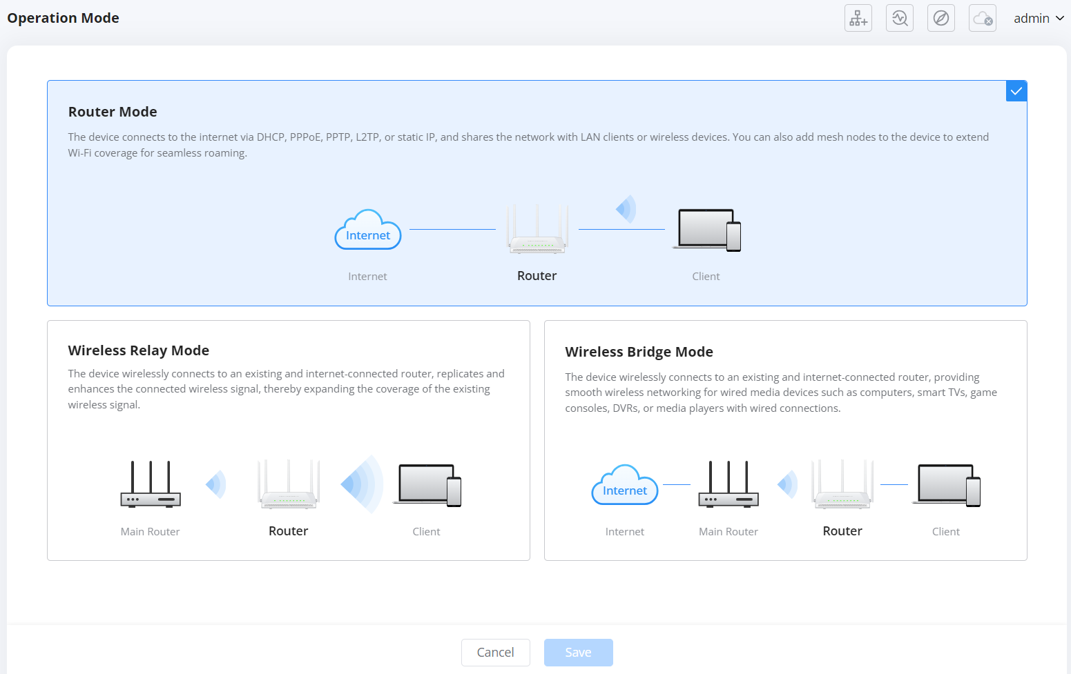
- Wireless Relay Mode
The router supports Wireless Relay Mode, allowing the device to connect wirelessly to an existing router and extend the wireless coverage. In this mode, all Ethernet ports on the device become LAN ports, and the device rebroadcasts the same SSID (network name) of the source router. Devices connected via LAN will obtain IP addresses from the main router.
Steps to Configure Wireless Relay Mode:
Navigate to Working Mode. Go to System → Working Mode in the left menu. Select Wireless Relay Mode from the available options: Router Mode, Wireless Relay Mode, or Wireless Bridge Mode.
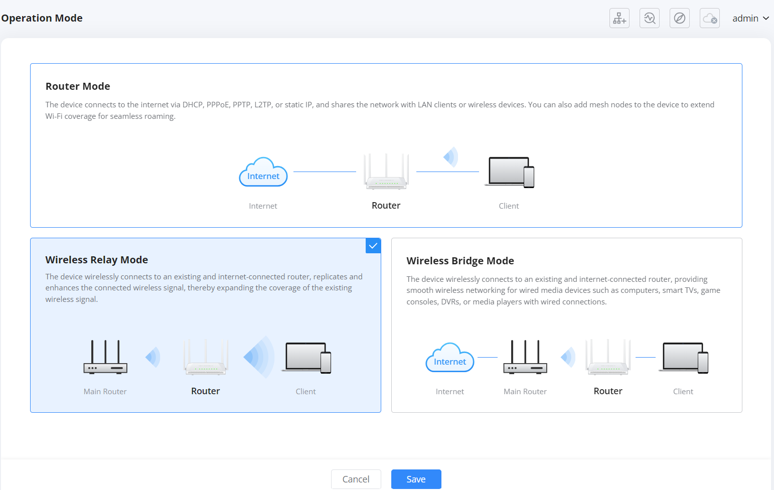
Confirmation Prompt After selecting Wireless Relay Mode, a confirmation dialog will appear stating: “After switching, all sub-nodes managed by this device will be automatically unbound.” Click Switch to proceed.

Step 1 – Preparations The screen will guide you through preparations:
- Ensure a wireless network is available and that this device is placed within signal range.
- Make sure the device is not connected to any other network via Ethernet cable. Click Next to continue.

Step 2 – Select Wi-Fi. The device will scan for nearby Wi-Fi networks. Select the desired network (SSID) you wish the GWN7062M to connect to.

Enter Wi-Fi Password. Once the SSID is selected, a prompt will appear requesting the Wi-Fi password. Enter the correct credentials and click OK.

Step 3 – Configuration Complete. The device will now apply the settings and reboot. Do not power off the unit. Wait for the LED to turn solid blue before using the router.

Notes:
- In this mode, the router replicates and extends the existing Wi-Fi network.
- All LAN ports can be used to connect wired clients, which will receive IP addresses from the main router.
- This is ideal for extending Wi-Fi coverage without using cables.
You have successfully configured Wireless Relay Mode.
- Wireless Bridge Mode
The router supports Wireless Bridge Mode, allowing the device to wirelessly connect to an existing internet-connected router. Once connected, the device disables its wireless broadcasting and converts all Ethernet ports into LAN ports for wired client connections. This mode is ideal for connecting wired-only devices such as smart TVs, DVRs, game consoles, and desktop computers to a remote Wi-Fi network.
To set up Wireless Bridge Mode:
- Navigate to Working Mode
Go to System → Working Mode, then select Wireless Bridge Mode and click Save.
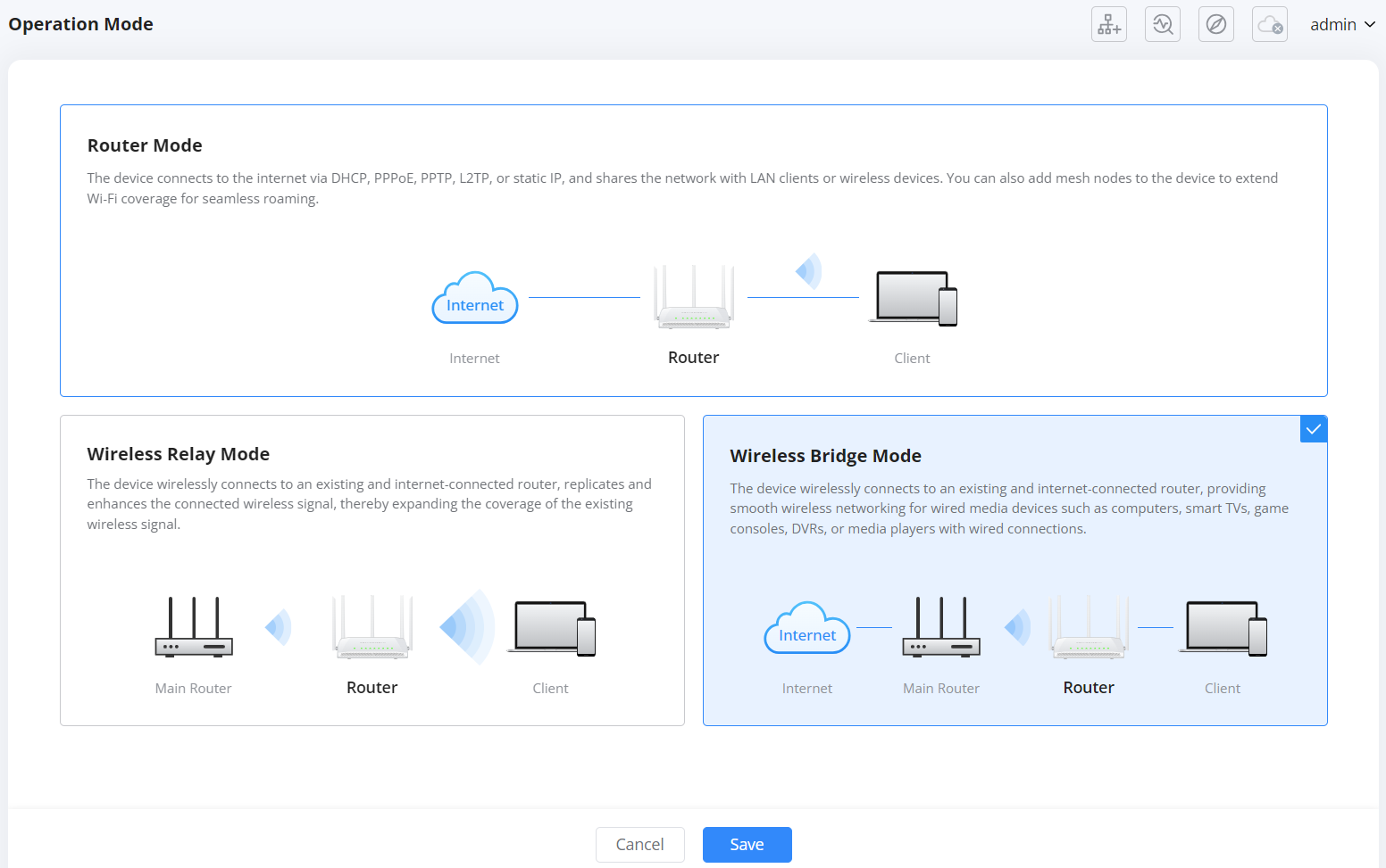
- Confirm Mode Switch
A prompt will appear stating that all sub-nodes managed by the device will be unbound. Click Switch to proceed.

- Read Preparations
The screen will display key instructions:
- The device will no longer provide wireless connectivity.
- All Ethernet ports will serve as LAN ports for data transmission.
- Ensure the device is not connected to any network via cable and is placed within Wi-Fi range of the main router.
Click Next to continue.

- Select Wi-Fi
The device will scan for available Wi-Fi networks. Choose the network you want to connect to and click Next.

- Enter Wi-Fi Password
Enter the password of the selected Wi-Fi network and confirm by clicking OK.

- Reboot and Finish
The device will apply the settings and automatically reboot. Wait until the LED turns solid blue before using it. You can now connect wired clients to the router’s LAN ports, and they will obtain IP addresses from the main router.

CHANGE LOG
This section documents significant changes from previous versions of the GWN7062M router user manuals. Only major new features or major document updates are listed here. Minor updates for corrections or editing are not documented here.
Firmware Version 1.0.1.92
- This is the initial release.
All product names, logos, and brands mentioned in this document are the property of their respective owners. Windows® is a registered trademark of Microsoft Corporation. iOS® is a registered trademark of Apple Inc. Android® is a registered trademark of Google LLC. Samsung® is a registered trademark of Samsung Electronics Co., Ltd.