


Introduction
The In-Wall Mounting Kit allows the GDS3725 or GDS3726 door system to be installed into a solid wall or drywall surface for a clean, professional finish.
It includes all components required for mounting, securing, and aligning the unit properly within the wall cavity.
Package Contents
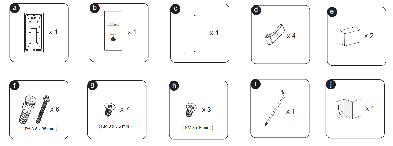
| Label | Item | Quantity | Specification |
|---|---|---|---|
| a | In-Wall Bracket | ×1 | Main frame for device installation |
| b | Mounting Template | ×1 | Used for hole marking and cutting guide |
| c | Front Frame | ×1 | Decorative outer frame for finish |
| d | Cable Clamp | ×4 | Used for securing internal wiring |
| e | Back Box | ×2 | For cable and module containment |
| f | Plastic Wall Anchors + Screws | ×6 | PA 3.5 × 35 mm |
| g | Mounting Screws | ×7 | KM 3 × 5.5 mm |
| h | Front Frame Screws | ×3 | KM 3 × 6 mm |
| i | Allen Key | ×1 | Used for tightening the frame screws |
| j | Quick Installation Leaflet | ×1 | Printed reference guide |
Drywall (Hollow Wall) Installation
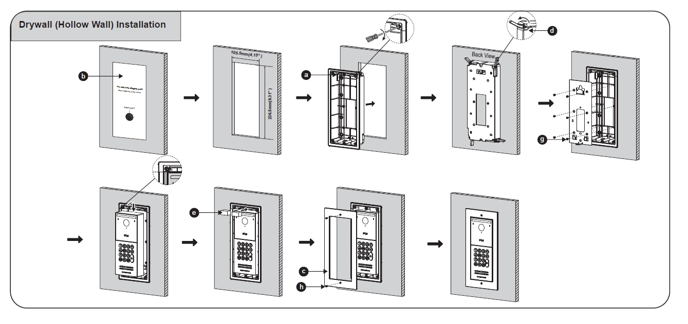
Mark the Opening
- Place the mounting template (b) on the wall and mark the outline.
- Cut a rectangular opening following the indicated dimensions (105.5 mm × 263.5 mm / 4.15″ × 10.37″).
Insert the In-Wall Bracket
- Position the bracket (a) into the opening and adjust it flush to the wall surface.
Secure the Bracket
- Use the cable clamps (d) on the inside to fasten the bracket edges against the drywall for firm support.
Mount the Device
- Connect cables through the back boxes (e).
- Attach the GDS device using the KM 3 × 5.5 mm screws (g) into the bracket mounting points.
Attach the Front Frame
- Position the front frame (c) over the device.
- Secure it using the KM 3 × 6 mm screws (h) tightened with the Allen key (i).
Final Check
- Verify alignment and ensure the device is fully flush with the wall.
Solid Wall Installation
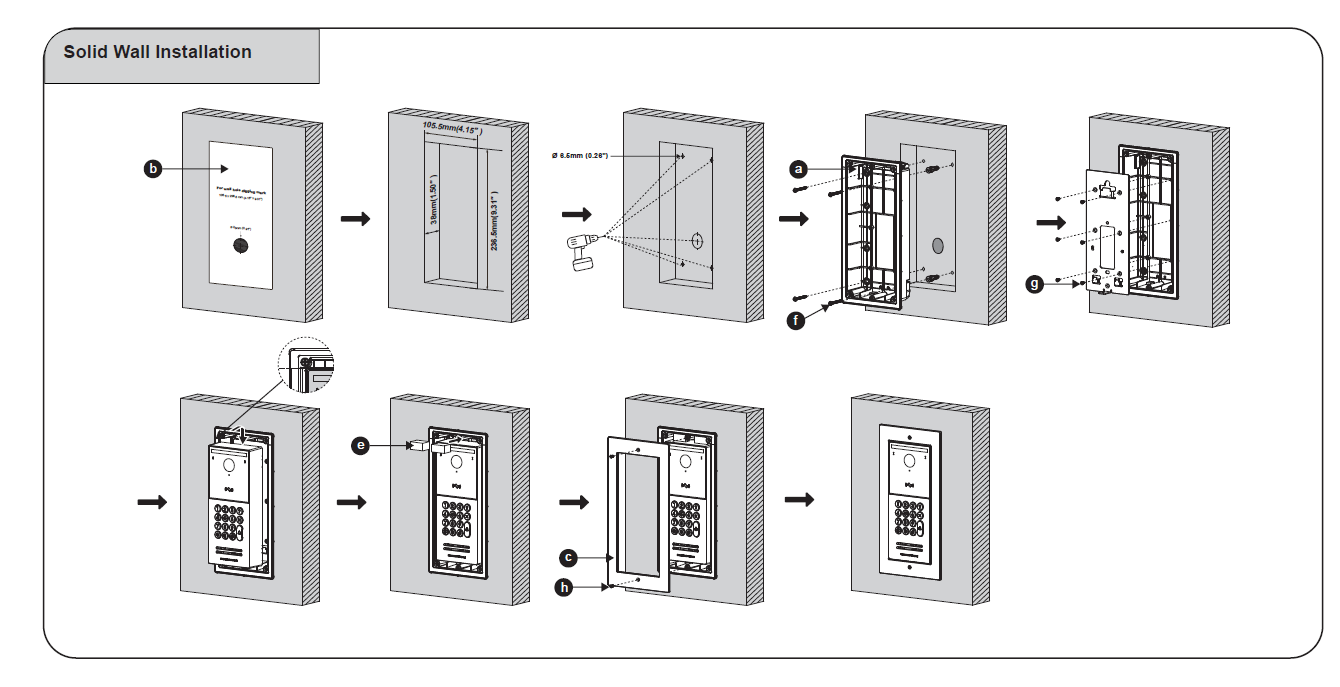
Mark and Drill
- Place the template (b) and mark the opening area on the wall.
- Cut a recess measuring 105.5 mm × 263.5 mm (4.15″ × 10.37″) with a depth of 38 mm (1.5″).
- Drill six holes (Ø 6.5 mm / 0.26″) at the screw positions.
Insert Anchors
- Place PA 3.5 × 35 mm wall anchors (f) into the drilled holes.
Mount the Bracket
- Align the in-wall bracket (a) with the holes and secure it using the provided screws.
Install the Device
- Pass the cables through the back boxes (e) and connect them to the GDS unit.
- Fasten the device onto the bracket using KM 3 × 5.5 mm screws (g).
Finish with the Front Frame
- Place the front frame (c) over the device.
- Tighten with KM 3 × 6 mm screws (h) using the Allen key (i) for a flush appearance.
Confirm Installation
- Ensure the front surface is even with the wall and all screws are securely fastened.