Thank you for purchasing the Grandstream GDS370x Audio Door Access System.
The GDS3705 was built for users looking for a strong audio-only facility access and security monitoring solution that can be deployed in environments of all sizes. This audio door system features dual microphones and an HD loudspeaker with advanced AEC to offer intercom functionality, can support SIP calls to IP phones, and has a built-in RFID chip reader and keypad for secured keyless or key entry. The GDS3705 comes equipped with a zinc alloy metal casing, making it weatherproof and vandal-resistant, and offers alarm-in and alarm-out support for integration with existing security devices. The GDS3705 integrates with Grandstream’s free management utility software, GDS Manager, allowing RFID card information, as well as the device itself, to be fully managed by this software. Thanks to its integration with other Grandstream endpoints like the GXP IP phones, GXV video phones, portable WiFi, and DECT IP phones, and the Grandstream Wave mobile app, the GDS3705 offers a complete end-to-end solution for access control, audio intercom, and security needs
The GDS3702 is an HD Audio IP Intercom System to offer remote facility access control for buildings of all sizes. This device includes a built-in microphone and speaker to support intercom functionality, supports integration with electric locks for locking and unlocking doors, and offers alarm-in and alarm-out support for integration with existing security systems. The GDS3702 works with Grandstream’s free management software, GDS Manager. It features SIP/VoIP technology with 2-way HD audio, IP66 level weatherproof casing, and is vandal-resistant. The combination of the GDS3702, Grandstream’s IP Phones, Wave mobile app, and other 3rd party IP devices provides a complete end-to-end solution for access control and intercom needs.
PRODUCT OVERVIEW
Feature Highlights
The following table contains the major features of the GDS370x.
4 SIP accounts and 4 lines.
Broad interoperability with most 3rd party SIP/VoIP devices and leading SIP/NGN/IMS platforms
2 Channels Input/Output alarm.
RS485, Wiegand (26 bits) Input and Output.
RFID card reader.
Weatherproof, vandal resistant.
Built-in microphone and speaker offers voice options and intercom functionality
4 SIP accounts and 4 lines.
Broad interoperability with most 3rd party SIP/VoIP devices and leading SIP/NGN/IMS platforms
2 Relay for Electric Lock and Alarm out, 2 Alarm In for Exit button and door sensor
Weatherproof, vandal resistant.
Built-in microphone and speaker offers voice options and intercom functionality
GDS370x Features at a Glance
Technical Specifications
The following table summarizes all the technical specifications, including the protocols/standards supported, voice codecs, telephony features, and upgrade/provisioning settings for GDS370x.
GDS3705
Network Protocols
TCP/IP/UDP, RTP/RTCP/RTCP-XR, HTTP/HTTPS local upload and mass provisioning using TR-069, ARP/RARP, ICMP, DNS, DHCP, SSH, SMTP, NTP, STUN, TLS, SRTP.
SIP/VoIP Support
Broad interoperability with most 3rd party SIP/VoIP devices and leading SIP/NGN/IMS platforms.
This chapter provides basic installation instructions, including a list of the packaging contents and information for obtaining the best performance using the GDS370x Audio Access Door System.
Equipment Packaging
GDS3705
1 x GDS3705.
1 x Installation Bracket.
1 x Drilling Template.
4 x Rubber Gaskets (for sealing the back cable).
6 x Back Panel Screws.
6 x Bracket Screws and Anchors.
4 x Anti-tamper screws.
1 x Anti-Tamper Hex Key.
1 x Wiegand Cable.
1 x RFID Card (more can be purchased from Partner/reseller).
1 x Key Fob (more can be purchased from Partner/reseller).
1 x Frame Back Cover.
1 x Quick Installation Guide.
1 x GPL License.
GDS3705 Package
GDS3702
1 x GDS3702.
1 x Installation Bracket.
1 x Drilling Template.
4 x Rubber Gaskets (for sealing the back cable).
6 x Back Panel Screws.
6 x Bracket Screws and Anchors.
1 x Wiegand Cable.
1 x Anti-Tamper Hex Key.
4 x Anti-tamper screws.
1 x Frame Back Cover.
1 x Quick Installation Guide.
GDS3702 Package
Note
Check the package before installation. If you find anything missing, contact your system administrator.
Description of the GDS370x
The following figures show the components of the back and front views of the GDS370x IP Audio Access Door System:
GDS3705
GDS3705 FrontBack View
GDS3702
GDS3702 FrontBack View
Connecting and Setting up the GDS370x
The GDS370x can be powered using PoE or a PSU:
Using PoE as a power supply (Suggested)
Connect the other end of the RJ45 cable to the PoE switch.
A PoE injector can be used if the PoE switch is not available.
Using the power adapter as a power supply (PSU not provided)
Connect the other end of the RJ45 cable to the network switch or router.
Connect the DC 12V power source via the related cable to the corrected PIN of the GDS370x.
GDS370x Wiring Connection
Jack
Signal
Function
Note
J2 (Basic) 3.81mm
TX+
Ethernet PoE 802.3af Class 3, 12.95W
Orange / White
Data
TX-
Orange
RX+
Green / White
RX-
Green
PoE_SP2
Blue + Blue/White
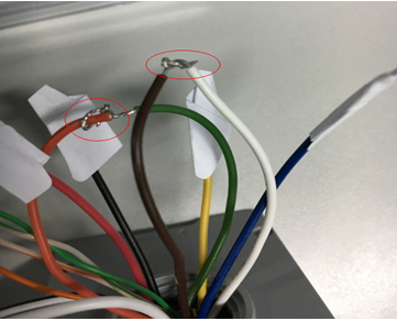
Please twist these two wires together and connect to SP1, SP2 respectively even the PoE NOT used.
PoE_SP1
Brown + Brown/White
RS485_B
RS485
RS485_A
GND
Power Supply
DC 12V, 1A Minimum
12V
J3 (Advanced) 3.81mm
GND
Alarm GND
ALARM1_IN+
Alarm In
Vin<15V
ALARM1_IN-
ALARM2_IN+
ALARM2_IN-
NO1
Alarm Out
Relay: 30VDC/2A; 125VAC/0.5A
COM1
NO2
Electric Lock
For “Fail Secure” (Locked when Power Lost) Strike, connect COM2 & NO2.
For “FailSafe” (Open when No Power) Magnetic Lock, connect COM2 & NC2.
Relay: 30VDC/2A; 125VAC/0.5A
COM2
NC2
J4 (Special) 2.0mm
GND
Wiegand Power GND
Black
Both Input and Output MUST be connected
WG_D1_OUT
Wiegand Output Signal
Orange
GDS3705 function as Output of Card Reader, Connect Pin 1, 2, 3
WG_D0_OUT
Brown
LED
Wiegand Output LED Signal
Blue
For External Card Reader; Or GDS3705 as Receiver Only
WG_D1_IN
Wiegand Input Signal
White
For External Card Reader Connect Pin 1,4,5,6,7,8
WG_D0_IN
Green
BEEP
Wiegand Output BEEP Signal
Yellow
For External Reader Only
5V
Wiegand Power Output
Red
For External Card Reader Only. 12VDC powered External Card Reader must use own power source, can NOT use this Pin.
GDS3705 Wiring Connection
GDS370x Back Cover Connections
GDS370x Back Cover Connections
Connection Example
To connect the GDS either by using PoE or PSU, follow the steps below:
Open the Back-Cover Board of the GDS370x, which should look like the following figure.
GDS370x Back Cover
Power GDS370x using PoE
Cut into the plastic sheath of your Ethernet cable, then unwind and pair as shown below.
Use the TIA/EIA 568-B standard, which defines pin-outs for using Unshielded Twisted Pair cable and RJ-45 connectors for Ethernet connectivity.
Connection Example
Connect each wire of the cable to its associate on the Back Cover of the GDS370x to power the unit using PoE.
Power GDS370x using PSU
To power the unit using a PSU, use a multimeter to detect the polarity of your Power Supply, then connect GND to the negative pole and 12V to the positive pole of the PSU.
Note
If the user doesn’t have a PoE switch, there is no need to connect the Blue and Brown wires to the GDS370x since these wires are used to power the unit via Ethernet.
Powering the GDS370x
GETTING TO KNOW GDS370x
The GDS370x has an embedded Web server to respond to HTTP/HTTPS GET/POST requests. Embedded HTML pages allow users to configure the GDS370x through all available Web browsers on the internet.
Connecting GDS370x to the Network with a DHCP Server
The GDS370x, by default, has a DHCP client enabled; it will automatically get an IP address from the DHCP server.
Windows Platform
Two ways exist for Windows users to get access to the GDS370x:
UPnP
By default, the GDS370x has the UPnP feature turned ON. For customers using a Windows network with UPnP turned on (most SOHO routers support UPnP), it is very easy to access the GDS370x:
Find the “Network” icon on the Windows Desktop.
Click the icon to get into the “Network”, the GDS370Xs will list as “Other Devices”, shown below. Refresh the pages if nothing is displayed. Otherwise, the UPnP may not be active in the network.
Figure 8 Detecting GDS370x via UPnP
3. Click on the displayed icon of related GDS370x, and the default browser (e.g., Internet Explorer, Firefox, or Chrome) will open and connect directly to the login webpage.
GDS3705 Login Page
GS Search
GS search is a program that is used to detect and capture the IP address of Grandstream devices. Below are instructions for using the “GS Search” utility tool:
Download the GS Search utility tool from the Grandstream website using the following link: GS_Search
Double-click on the downloaded file, and the search window will appear.
Click on button to start the discovery for Grandstream devices.
The detected devices will appear in the output field like below.
GS Search Discovery
Double-click on a device to access its web GUI.
GDS Manager Utility Tool
Users can know the IP address assigned to the GDS370x from the DHCP server log or using the Grandstream GDS Manager after installing this free utility tool provided by Grandstream. Users can find instructions below for using the “GDS Manager” utility tool:
Download the GDS Manager utility tool from the Grandstream website using the following link: GDSManager Download
Install and run the Grandstream GDS Manager, a client/server architecture application. The server should be running first, then GDSManager (client) later:
3. On the GDS Manager, access Device 🡪 Search and click on the button to start device detection
4. The detected devices will appear in the output field like below:
GDS370x Detection using GDS Manager
5. Double-click the column of the detected GDS370x, and the browser will automatically open and show the device’s web configuration page.
6. Enter the administrator user name and password to access the Web Configuration Interface. The default admin username is “admin”, and the default random password can be found on the sticker on the GDS3705.
Connect to the GDS370x using a Static IP
If there is no DHCP server in the network, or the GDS370x does not get an IP from the DHCP server, the user can connect the GDS370x to a computer directly, using a static IP to configure the GDS370x.
The default IP, if no DHCP server or DHCP request times out (after 3 minutes), is 192.168.1.168
Connect the Ethernet cable from GDS370x to the computer network port directly.
Configure the computer using Static IP: 192.168.1.XXX (1<XXX<255, except for 168) and configure the “Subnet mask” to “255.255.255.0”. Leave the “Default Gateway” to “Blank” like below:
Static IP on Windows
4. Power on the GDS370x, using a PoE injector or external DC power.
5. Enter 192.168.1.168 in the address bar of the browser, and log in to the device with admin credentials. The default admin username is “admin”, and the default random password can be found on the sticker on the GDS3705.
GDS370x APPLICATION SCENARIOS
The GDS370x Door System can be used in different scenarios. We will be using the GDS3705 Model as our testing unit.
Peering Mode without SIP Server
For environments like remote warehouse/storage, grocery store, small (take-out) restaurants, just using static IP with a PoE switch to form a LAN, using Grandstream’s audio phone GXP21XX/17XX/16XX series, the GDS370x will meet your very basic intercom and open-door requirements.
This is the solution to upgrade the traditional analog Intercom system. All you need is a Power source, a Switch or a PoE Switch, and Grandstream IP phones.
The equipment list can be found below:
GDS370x
Grandstream IP Phones
PoE Switch with related Cat5e/Cat6 wiring
Peering using SIP Server (UCM6XXX)
For large deployments, multiple GDS370x units might be required, peered connections will not work in such a case due to multiple connections. Such scenarios require an IPPBX or a SIP Proxy to accomplish the tasks.
If remote access is required, a router with internet access should be added to the below-needed equipment list:
Several GDS370x
UCM6XX or another SIP Server
Grandstream IP Phones
PoE Switch with related Cat5e/Cat6 wiring
Electronic Lock
Peering GDS3705 with UCM6XXX
GDS370x PERIPHERAL CONNECTIONS
Below is the illustration of GDS370x peripheral connections for related applications.
Peripheral Connections for GDS370x
Alarm IN/OUT
Alarm_In could use any 3rd-party Sensor (like an IR Motion Sensor).
Alarm_Out device could use a 3rd party Siren, Strobe Light, or Electric Door Striker, etc.
The figure below shows an illustration of the Circuit for Alarm_In and Alarm_Out.
Alarm InOut Circuit for GDS370x
Notes:
The Alarm_In and Alarm_Out circuit for the GDS370x should meet the following requirements:
Alarm Input
3V<Vin<15V, PINs (1.02KΩ)
Alarm Output
125VAC/0.5A, 30VDC/2A, Normal Open, PINs
The Alarm_In circuit, if there is any voltage change between 3V and 15V, as specified in the table above, the GDS370x Alarm_In port will detect it and trigger the action and event.
Higher voltage and wrong polarity connections are prohibited because this will damage the devices.
Protection Diode
When connecting the GDS370x to a door strike, it is recommended to set an EMF protection diode in reverse polarity for secure use. Below are examples of deployment for the protection diode.
Protection Diode Example 1
The reverse EMF protection diode must always be installed in reverse polarity across the door strike.
Protection Diode Example 2
Connection Examples
Below are examples showing how to use wiring on the back cover of the GDS370x to connect with external devices. The “NO” (Normal Open) model strike is used as an example; “NC” (Normal Closed) should be similar, and users need to decide which model (NO or NC) to use on the door.
Wiring Sample using 3rd Party Power Supply
3rd party Power Supply Wiring Sample
Wiring Sample using Power Supply for both GDS370x and Electric Strike
Power Supply used for both GDS370x and Electric Strike
Wiring Sample using PoE to power GDS370x and 3rd Party Power Supply for Electric Strike
Wiring Sample using PoE to power GDS370x and a 3rd party Power Supply for Electric Strike
Warning
The following example should be avoided when powering the electric strike.
Example to Avoid when Powering the Electric Strike
Good Wiring Sample for Electric Strike and High-Power Device
Electric Strike and High Power Device Example
Wiegand Module Wiring Examples
The GDS370x package is shipped with one Wiegand cable for Input/Output Wiegand connections. The following examples show how to connect the Wiegand Input/Output devices to the GDS370x.
Input example with 3rd party power supply for Wiegand device
Wiegand Input Example with 3rd party Power Supply
Make sure to connect the GND of the Wiegand device and the GDS370x Wiegand port.
For the Wiegand input mode, the LED and Beep pins require that the Wiegand device support those interfaces. These two pins will not affect the Wiegand bus when not connected.
Input example with power supply for both GDS370x and Wiegand device
Wiegand Input Example with Power Supply for GDS370x and Wiegand Device
If the power source is 12VDC, the Wiegand device can share the same power source as GDS370x. However, users need to check the max power consumption and the max capability of the power source.
If the Wiegand device is using 5VDC, the GDS370x Wiegand port can provide 5VDC with a max 500mA to power up the Wiegand device.
Output example with 3rd party power supply for Wiegand device
Wiegand Output Wiring Example
When the Wiegand output of the GDS370x is connected, it acts as the signal receiver of the 3rd party Wiegand device, connecting to the door controller. The major wiring is GND, D0, and D1. Because usually, the door controller will consume a large amount of current and power, the power supply should be separated.
Wiegand RFID Card Reader Example
Note
The RFID card scan on the GDS is supported only on the GDS3705 Model.
Wiegand RFID Card Reader Example
The siren alarm when the door opened abnormally
When this feature is enabled (special wiring required, see below wiring diagram), an abnormal open door will be detected by the DI port (Alarm_In2 or IN2 in the diagram below) if wired correctly (connecting the COMx port to DIx port), therefore triggering the siren alarm. Once an abnormal open door alarm is triggered, the siren will sound nonstop until manually overridden by a related person.
There are several ways to stop and disable the alarm:
Power cycle the GDS370x
Pick up the Alarm Phone Call (if configured)
Open Door using a PIN (either public PIN or private PIN) for the GDS3705 Model only.
Once the alarm is triggered, the GDS370x will play a siren sound, send an email to the administrator (if configured with SMTP), call the configured alarm SIP phone, and send the alarm output (if connected). Users will only be able to disable the siren using the 3 methods mentioned above.
For detailed action information, please refer to the GDS37xx User Manual, “Alarm Action Settings” configuration. Below are some diagrams showing the correct wiring to enable this new security enhancement feature.
GDS370x Connection: IN2 set as Normal Close and “Fail-Safe” Electric Strike using 3rd Party Power Supply
Digital Input set as Normal close
Failsafe Electric Strike using 3rd Party Power Supply
GDS370x Connection: IN2 set as Normal Open and “Fail Secure” Electric Strike using 3rd Party Power Supply
Digital Input set as Normal open
Fail Secure Electric Strike using 3rd Party Power Supply
Open Door via GDS370x with or without a SIP Call
This feature needs a related matching GDS370x firmware to work. The minimum firmware version needed:
GDS370x: 1.0.1.16 or higher.
From the GDS3705 side, the configuration is the same. The only difference is the number of doors to be controlled: If using Local Relay controlled by GDS3705, TWO DOORS can be controlled.
If using GSC3570 Relay, ONLY ONE DOOR can be controlled. The PIN and other settings are the same as the SIP remote open door or the GSC3570 secure open door.
The difference will come out in the touch screen UI operation of GSC3570.
GDS3705 Configuration Example
GSC3570 Configuration Example
Door opening with SIP Call
When GSC3570 establishes a call with GDS370x, the screen will display the virtual open door button(s), and the user will press the button to open the door:
Open Door with SIP Call
Door opening without SIP Call
At the GSC3570 idle screen, press “Monitor →Door system”, and the related GDS370x will be displayed. In the blue bar, left is a “Phone” icon, and right is the “Open door” icon. The“Phone” icon will establish the SIP call as the previous firmware did.
Press the “Open door” icon, and the GSC3570 will open the door directly, and NO SIP CALL will be established. Depending on how many doors are controlled, if one door is configured, the door will open directly; if two doors are configured, another screen will pop up to allow the user to choose which door to open, as shown below:
Open Door without SIP Call
When the door is successfully opened, the following message will appear:
Open Door without SIP Call
Secure Open Door Peering with GSC3570
Secure open door feature is a paring scenario that is done between the GSC3570 control station and the GDS37xx door system, with GDS37xx installed outside, the GSC3570 is installed inside, the strike or lock is wired directly to the Alarm_Out interface of GSC3570 to control the door from inside, therefore more secure compared to the strike wired directly to GDS37xx outside. Below is the application scene illustration:
GSC3570 secure open door via GDS3705
Notes
Some considerations before configuring the Secure Open Door Peering with GDS37xx:
GDS371x firmware 1.0.7.19 or above / GDS370x firmware 1.0.1.13 or above are required to work with GSC3570.
Only one door can be controlled by the GSC3570 since it has only one Relay Control circuit.
If multiple doors need to be controlled by the GSC3570, then a SIP call is required, and the door strike/relay should be controlled by the related GDS37xx directly.
The GSC3570 will turn on the LCD when the device is in energy save mode (LCD Off) when a secure open door event happens.
When receiving an incoming call, a 3rd party audio/light strike device can be triggered by the Door Open Port when wired properly on the GSC3570 side.
When implementing a secure open door, the door relay mode should be set to GSC3570 Relay.
When configured correctly, the GSC3570 Secure Open Door will function with all GDS37xx open door modes: RFID card, Local PIN, Remote PIN (SIP Call or DTMF Open Door).
RFID card can be used only on the GDS3710 and GDS3705 models.
When using IP peering, the SIP Transport must be set to “UDP”.
When using IP Peering, a static IP address in the same LAN must be used, and the related The account needs to be configured with “No” in the NAT Traversal.
Remote open door without being in SIP direct IP is supported only on GDS3710/GDS3712 models.
Please refer to the following configuration guide to learn more about setting up Secure Open Door Peering with GDS37xx: Peering GDS with GSC3570
GDS370x HOME WEB PAGE
Once the IP address of the GDS370x is entered on the user’s browser, the login web page will pop up, allowing the user to configure the GDS370x parameters.
When clicking on the “Language” drop-down, supported languages will be displayed as shown in the Figure below. Click to select the related webpage display language.
GDS3705
Change Language Page on GDS3705
GDS3702
Change Language Page on GDS3702
Note
Current firmware supports only English (default) and simplified Chinese.
GDS370x SETTINGS
Door System Settings
Users can configure system operation parameters, like input PIN for the door (GDS3705 Model only), and manage users’ settings.
Basic Settings
Door System Settings Page
Door Relay Options
There are three choices in the pull-down selection: Local Relay, Webrelay and GSC3570.
Local Relay: Local Relay is the GDS3705 controlling the relay. The strike is wired into the COM2 or COM1 port of the GDS3705 depending 1 door or 2 door need to be controlled.
Webrelay: When Webrelay is selected, customers need to continue configure the webrelay IP address or domain name, together with credentials like Username and Password. When legal open door event happened, the configured web relay will get the communication from GDS3705, and will operate the strike to open door for the authenticated open door request.
GSC3570 Relay: When the Door relay is set to GSC3570, it gives the option to connect it to the GSC3570 device by entering the Phone number and door password
Note: In web relay mode, the strike is wired to the web relay controller device.
Webrelay On URL
When Door relay Option set to Webrelay, then enter the correct URL used by the third party controller so that the GDS370x send the command to activate the relay.
This adds an extra layer of security so when legal open door event happened, the configured web relay will get the communication from GDS370x, and will operate the strike to open door for the authenticated open door request or use that command to operate other industry application.
Notes:
Now there are two Webrelay URL fields available, with On or Off URL command allowed or other usage URL command allowed. Also allow Username and Password configured if the 3rdparty Webrelay requiring this security feature.
If some 3rd party Webrelay only support one URL command, then just leave another Off URL blank, or put whatever there as long as it is NOT a URL command.
Webrelay Off URL
When Door relay Option set to Webrelay, then enter the correct URL used by the 3rd party controller so that the GDS3705 send the command to disable the relay.
Webrelay Username
Enter the web relay username.
Webrelay Password
Enter the web relay password.
ALMOUT1 Feature
This option allows to choose to use Alarm_Out (COM1) interface for either as alarm out with 3rd party device, or to control a second door “Door 2” (the two functions are mutual exclusive).
When option “Open Door” is selected, will enable GDS3705 to control the operation of two doors via RFID, local and remote PINs.
ALMOUT1 Status
Select Normal Open or Normal Close depending on the lock used.
Delay before Unlock (s)
Device will open door after specified delay (in seconds) when user issuing the authorization.
Unlock Holding Time (s)
Configures the lock holding time, in seconds (default value is 5 seconds).
Device will hold the door unlocked for this specified duration.
Range: 1-1800 seconds.
Minimum Interval of Swiping Card (ms)
Defines the interval in ms to swipe consecutive RFID cards. The range should be between 0ms and 2000ms. Default 300 ms. Note: Configuration available only on the GDS3705.
GSC3570 Phone Number
Incase of choosing a GSC3570 Relay , the Phone number of the GSC3570 needs to be defined on this field.
GSC3570 Door Password
Incase of choosing a GSC3570 Relay , the Door Password of the GSC3570 needs to be defined on this field.
Call Mode
Chooses whether to make call to the SIP number or Virtual Number when dialing from the GDS3705 keypad. Note: Configuration only for the GDS3705 Model.
Doorbell Mode
Configures the action to be taken when the doorbell is pressed, three options are available:
Call Doorbell Number: when Doorbell is pressed, a call will be made to the “Number Called When Door Bell Pressed”. *This option will be the only available when ALMOUT1 Feature is set to Open Door.
Control Doorbell Output (Digital Output 1): when Door Bell is pressed electronic lock for Output 1 is opened.
Both of Above: When selected, both Call Doorbell Number and Control Doorbell Output options are enabled.
Doorbell Call Out Account
This option sets the account to be used to make call upon the doorbell trigger. If set to Auto, the GDS will use the first available account.
Door Bell Call Mode
Select the ring strategy for the Numbers Called when pressing the Door Bell button to be either Serial or Parallel:
Serial Hunting: the configured extensions and/or IP addresses will ring one after one by order.
Parallel Hunting: The configured extensions and/or IP addresses will ring simultaneously (up to 4 simultaneous SIP calls).
Press Doorbell Schedule 1
Sets the first doorbell schedule , the device will verify if current time fits in the schedule , if yes it will dial out using the configured number in the field “Number 1 Called When Doorbell Pressed”
Number 1 Called When Door Bell Pressed
Configures SIP extension number (SIP Server mode), or IP address with port number (peering mode), to be called when the Door Bell is pressed:
SIP Server Mode:
The field can be configured to store multiple one or multiple SIP extensions, if configured with multiple extensions (ex: 1001, 1002, 1003), separated with “,” the GDS3705 will ring one extension after the other in a Serial Hunting Mode (GDS will ring each extension by default 15 seconds, this can be changed on the Ring Timeout) or ring them simultaneously in Parallel Hunting Mode.
When using UCM, users can also configure there a Ring Group extension (6400 for example) that will ring multiple extensions simultaneously, or one by one depending on the Ring Group ring strategy
If all phones are GXP21XX, users can open door either by pressing Remote_PIN# or by pressing Open Door button if already configured.
If early medial is enabled on phone side, user can send the PIN code using the Open-Door button before answering the call (Of course users can open the door also after answering the call).
Peering Mode:
User should configure multiple IP addresses of phones instead of SIP extensions, when Door Bell pressed the GDS3705 will ring the configured IP Addresses in Serial or Parallel Mode according to Doorbell Call Mode strategy.
Note: This field supports a Maximum of 256 characters.
Note: The latest firmware version 1.0.3.11 now supports configuring different “Number Called When Door Bell Pressed” entries depending on the time frame.
Press Doorbell Schedule 2
Sets the second doorbell schedule , the device will verify if current time fits in the schedule , if yes it will dial out using the configured number in the field “Number 2 Called When Doorbell Pressed”
Number 2 Called When Door Bell Pressed
Configures SIP extension number (SIP Server mode), or IP address with port number (peering mode), to be called when the Door Bell is pressed: SIP Server Mode: The field can be configured to store multiple one or multiple SIP extensions, if configured with multiple extensions (ex: 1001, 1002, 1003), separated with “,” the GDS370x will ring one extension after the other in a Serial Hunting Mode (GDS will ring each extension by default 15 seconds, this can be changed on the Ring Timeout) or ring them simultaneously in Parallel Hunting Mode. When using UCM, users can also configure there a Ring Group extension (6400 for example) that will ring multiple extensions simultaneously, or one by one depending on the Ring Group ring strategy If all phones are GXP21XX, users can open door either by pressing Remote_PIN# or by pressing Open Door button if already configured on the GDS3705 Model only. If early medial is enabled on phone side, user can send the PIN code using the Open-Door button before answering the call (Of course users can open the door also after answering the call). Peering Mode: User should configure multiple IP addresses of phones instead of SIP extensions, when Door Bell pressed the GDS370x will ring the configured IP Addresses in Serial or Parallel Mode according to Doorbell Call Mode strategy. Note: This field supports a Maximum of 256 characters. Note: The latest firmware version 1.0.3.11 now supports configuring different “Number Called When Door Bell Pressed” entries depending on the time frame.
Press Doorbell Schedule 3
Sets the third doorbell schedule , the device will verify if current time fits in the schedule , if yes it will dial out using the configured number in the field “Number 3 Called When Doorbell Pressed”
Number 3 Called When Door Bell Pressed
Configures SIP extension number (SIP Server mode), or IP address with port number (peering mode), to be called when the Door Bell is pressed: SIP Server Mode: The field can be configured to store multiple one or multiple SIP extensions, if configured with multiple extensions (ex: 1001, 1002, 1003), separated with “,” the GDS370x will ring one extension after the other in a Serial Hunting Mode (GDS will ring each extension by default 15 seconds, this can be changed on the Ring Timeout) or ring them simultaneously in Parallel Hunting Mode. When using UCM, users can also configure there a Ring Group extension (6400 for example) that will ring multiple extensions simultaneously, or one by one depending on the Ring Group ring strategy If all phones are GXP21XX, users can open door either by pressing Remote_PIN# or by pressing Open Door button if already configured on the GDS3705 Model only. If early medial is enabled on phone side, user can send the PIN code using the Open-Door button before answering the call (Of course users can open the door also after answering the call). Peering Mode: User should configure multiple IP addresses of phones instead of SIP extensions, when Door Bell pressed the GDS370x will ring the configured IP Addresses in Serial or Parallel Mode according to Doorbell Call Mode strategy. Note: This field supports a Maximum of 256 characters. Note: The latest firmware version 1.0.3.11 now supports configuring different “Number Called When Door Bell Pressed” entries depending on the time frame.
Press Doorbell Schedule 4
Sets the fourth doorbell schedule , the device will verify if current time fits in the schedule , if yes it will dial out using the configured number in the field “Number 4 Called When Doorbell Pressed”
Number 4 Called When Doorbell Pressed
Configures SIP extension number (SIP Server mode), or IP address with port number (peering mode), to be called when the Door Bell is pressed: SIP Server Mode: The field can be configured to store multiple one or multiple SIP extensions, if configured with multiple extensions (ex: 1001, 1002, 1003), separated with “,” the GDS370x will ring one extension after the other in a Serial Hunting Mode (GDS will ring each extension by default 15 seconds, this can be changed on the Ring Timeout) or ring them simultaneously in Parallel Hunting Mode. When using UCM, users can also configure there a Ring Group extension (6400 for example) that will ring multiple extensions simultaneously, or one by one depending on the Ring Group ring strategy If all phones are GXP21XX, users can open door either by pressing Remote_PIN# or by pressing Open Door button if already configured on the GDS3705 Model only. If early medial is enabled on phone side, user can send the PIN code using the Open-Door button before answering the call (Of course users can open the door also after answering the call). Peering Mode: User should configure multiple IP addresses of phones instead of SIP extensions, when Door Bell pressed the GDS370x will ring the configured IP Addresses in Serial or Parallel Mode according to Doorbell Call Mode strategy. Note: This field supports a Maximum of 256 characters. Note: The latest firmware version 1.0.3.11 now supports configuring different “Number Called When Door Bell Pressed” entries depending on the time frame.
Remote PIN to Open the Door
Configures PIN code stored in the GDS3705, remote SIP phone needs to input and match this PIN (the PIN is sent via DTMF while in call) so that the GDS3705 can open the door.
Note: For enhanced security, when the call is initiated from GDS then only the numbers existing in “White List” will be able to use DTMF PIN to open door remotely. Note: This configuration is available only on the GDS3705 Model.
Maximum Number of Dialed Digits
Configure the maximum digits allowed to dial in the keypad. Once the configured condition is satisfied, the device will automatically send the number to call without pressing #. It is disabled if set to 0. Note: Configuration can be done only on the GDS3705.
No Key Input Timeout (s)
Defines the timeout (in seconds) for no key entry. If no key is pressed after the timeout, the digits will be sent out without pressing #. The default value is 4 seconds. The valid range is from 1 to 15. Note: Configuration can be done only on the GDS3705.
Local PIN Type
Three options are available: Private Card PIN, Unified PIN or Card and Private PIN.
Private PIN: Means every member has a private PIN, the GDS will record who unlocked the door every time. Users need to enter the following sequence from the GDS3705 to open the door [*Virtual Number*Private PIN#].
Notes:
When Local PIN type is set to private PIN, users can also open the door by swiping their cards.
If “Disable Keypad SIP Number Dialing” is checked, users will be able to open door using private PIN with following sequence [Private PIN#].
Note: Door can still be opened by Card and with the sequence [*Virtual Number*Private PIN#].
Unified PIN: Means all members share a same PIN to unlock the door. Users need to enter the following sequence from the GDS3705 keypad to open the door [*Local PIN to Open Door#].
Card & Private PIN: Means every member needs to swipe his card and enter his private PIN to open the door using the following sequence [Swipe the card + * Private PIN#]
Local PIN to Open Door
Configures PIN stored in GDS3705, input locally this PIN on the GDS3705 keypad will unlock the door.
This feature needs Private PIN, means every member has a private PIN, the GDS will record who unlocked the door every time.
Users need to enter the following sequence from the GDS3705 to open the door [*Virtual Number*Private PIN#].
Note: When local PIN type is set to private card PIN, users can also open the door by swiping their cards.
Local PIN to Open Door Schedule
Configure a schedule for the Local PIN to open the door for “Unified PIN” mode only. Once configured, the door opening ability using local PIN with turn ON/OFF based on configured schedule. The schedule can ONLY be edited when “Central Mode” disabled.
Notes: If “Central Mode” enabled, the “Schedule” page cannot be edited. (a green “Central Model” label will display in top right corner of the UI).
When “Central Mode” enabled, the “Schedule” will be edited in GDSManager and synchronized by pulling from GDSManager down to GDS3705 device.
Default setting is “All Day”.
Enable DTMF Open Door
When enabled, remote SIP phones can open the door while in call by entering the remote PIN code configured (the PIN code is sent via DTMF). Default settings is disabled.
Enable Guest PIN
Enables password entry for guests.
Guest PIN
Configures the password that will be used by guests
Guest PIN Start Time
Selects the start time when the Guest PIN start to take effect.
Guest PIN End Time
Selects the end time when the Guest PIN will stop working.
Disable Auto Answer
If checked, GDS3705 will not answer incoming calls automatically, users can press any key to answer the call.
Default setting in unchecked.
Enable Doorbell Button to End Call
If checked, Users can hang up an active call when pressing the doorbell button. Enabled by Default.
Disable Keypad (except the Doorbell Button)
When checked the Keypad will be disabled, only Door Bell button can be pressed. Disabled by Default.
Enable On Hook After Remote Door Opened
When checked calls will be disconnected automatically 5 seconds after the remote open door event. Enabled by Default.
Onhook Timer After Remote Open Door (s)
When configured, the GDS37xx will keep the door unlocked for the configured period of time. The available range is “3-1800 seconds”. Default is 3 seconds.
Enable HTTP API Remote Open Door
Enabling this option allows to use HTTP API command to open the door remotely.
Disable: Disables remote door opening via HTTP API.
Challenge + Response Authentification:Uses a secure method requiring the client to answer a server challenge correctly before opening the door.
Basic Authentification: Uses a simpler method with a username and password encoded in the HTTP request header for authentication.
Notes:
PIN Code via Wiegand is sent on the HTTP response when HTTP API open door is executed.
“X-Content-Type-Options”, “HSTS(Strict-Transport-Security)”, “X-XSS-Protection” headers are included in the HTTP response to enhance security.
GDS370x will automatically reset to its default state after an API command is used to open the door, after the door is opened, the system automatically resets itself (goes on hook).
Please refer to the GDS HTTP API guide for more information on the HTTP commands supported.
Important note: We will not be responsible for any security problems resulting from opening the HTTP API remote function, this option is disabled by default and the user should enable it while knowing how to mitigate the risk.
HTTP API Open Door Compatibility Mode
Check to support HTTP API Open Door under HTTPS web access mode.
Disable Keypad SIP Number Dialing
When Keypad SIP number Dialing disabled, device will interpret each digit entry as private-password open door request after pressing #.
Notes:
“Local PIN Type” should choose “Private PIN”.
Dial keypad to make SIP call will NOT work (except for doorbell button call).
Private PIN must be UNIQUE among users, otherwise the door will still open but log will NOT tell who opened the door due to duplicated PIN and whoever user last matched in the database with the Private PIN will be shown in the log.
Note: Configuration can be done only on the GDS3705 Model.
Enable Card Issuing Mode
Enables RFID card issuing/program into the GDS3705. When selected sweeping an RFID card into the GDS3705 will add card information into [Card Management]. Note: Configuration Exclusive to the GDS3705 Model.
Card Issuing Mode Expired Timer(m)
Card issuing mode will be automatically disabled when timer reached (The range of value is 1 – 1440, in minutes). Default value is 5.
Enable Key Blue Light
When checked, the blue light will be activated when pressing the GDS3705 Keys.
Enable Doorbell Blue Light
When enabled, Keypad LED will light based on the configured Start/End Time. For instance, this option can be used when GDS is deployed on dark environment, the GDS will be located easily using Keypad LED. the Enable Doorbell Blue light can be scheduled by configuring a Start Time and End Time.
Enable Keypad Blue Light
When enabled, Keypad LED (except for Doorbell LED) will light based on the configured Start/End Time. For instance, this option can be used when GDS is deployed on dark environment, the GDS will be located easily using Keypad LED. the Enable Keypad Blue light can be scheduled by configuring a Start Time and End Time. Note: Configuration exclusive to the GDS3705.
Central Mode
If enabled, Group/Schedule/Holiday/Keep Door Open, can only be synchronized from the Central (GDS Manager), local configuration will not be allowed.
If disabled, only local configuration from GDS3705 is allowed.
Key Tone Type
Configures the key tones for the GDS3705.
Default: Beeps will be played when pressing the GDS3705 keys.
DTMF: Tones will be played when pressing the GDS3705 keys.
Mute: No sound will be played when pressing keys.
Enable Wiegand Input
This option needs to be enabled when GDS is connected to the wiegand. output device (RFID card reader for example)
Wiegand Output
This option is to be enabled when the GDS is the wiegand output device. (example: input device is a door controller)
Door System Settings
Note
Remote SIP phone needs a password (digits 0-9 only, ended with # key) matching the configuration on the web page to open the door via DTMF. (This feature is only supported on the GDS3705 Model)
GDS3705 supports RFID for multiple users to open the door, therefore, every user has their own PIN. For an environment with 100 users or more, it’s difficult for the GDS3705 to manage all these users, and a separate PC or Server should be involved for such a kind of management and monitoring.
In environments with more than 100 users the GDS3705, another possibility would be to set one unified Local PIN for opening the door for all the users.
Using Alarm Out (COM 1) to Control a Second Door
Note
The following configuration is exclusive to the GDS3705 Model.
Starting from firmware 1.0.0.41, the user can now set Alarm_Out (COM1) interface to control a second Door, in addition to the existing Locker/COM2 interface (controlling Door1).
This feature allows GDS3705 to control the operation of two doors via RFID, and local and remote PINs.
For example, a 3rd party Wiegand Input device or GDS3705 can be installed at Door2 with a related cable wired into the control GDS3705 installed at Door1. The Door1 and Door2 can be configured to be opened by programmed RFID cards and PINs, either separately or both.
Alarm Out1 Feature
Interface for Door Control (which Door can be OPEN):
Note
The following configuration is exclusive to the GDS3705 Model.
If the Alarm_Out (COM1) interface is set to control Door 2 opening, “ALMOUT1 Status” can be configured by choosing “Normal Open” or “Normal Close” based on the strike used.
Unlike the default COM2, which is designed for strike control and has three connecting sockets, COM1 only has two connecting sockets. Therefore correct lock mode has to be configured to make the strike work as expected.
For the above example, the GDS3705 is configured to control Door1 (wiring to COM2 interface); the 3rd party Wiegand Input is set to control Door2 (wiring to COM1 interface).
In case of a power loss then the DOOR STATUS when power is off will depend on the following situations:
COM2 has three wiring PINs, corresponding to NO or NC accordingly. Therefore, when connecting NC2 and COM2 (Fail Safe), the strike will open when power is lost, and when using a NO2 strike (connecting COM2 and NO2), the door is “locked” when power is lost (Fail Secure).
COM1 (ALMOUT1) has only two PINs and NO ONLY. If the connected strike/lock is a NO strike, this means ALMOUT1 Status should be set to “Normal Open” then the door will be closed when power is lost, while if the strike connected is NC strike, and ALMOUT1 Status is set to “Normal Close” then the door will be open when power is lost.
Universal PIN for Operation of Doors:
Note
The following configuration is exclusive to the GDS3705 Model.
Universal Local PIN
If Unified PIN (Universal PIN) is configured to open door, then which door can be controlled by the PIN is configured in the UI once “Unified PIN” is selected.
For example, like the above screenshot, if this universal PIN is set to open both Door1 and Door2, but due to the previous “Control Option” set to open Door1, and “Wiegand Control” set to open Door2, therefore the final result will be the INTERSECT result of both sets with condition qualified.
Remote PIN to Operation of Doors:
Note
The following configuration is exclusive to the GDS3705 Model.
For the remote PIN to open door, the PIN can be configured in example down below.
The PIN can be different for Door1 and Door2 and has to be configured correctly in the related IP Phone, which will be used to operate “One Key Open Door”.
If BOTH doors need to be opened at the same time, then both Door1 and Door2 have to be configured with the exact SAME password or PIN as the DTMF open door.
Note
For enhanced security, When call is initiated from GDS then only the numbers existing in “Number Called When Door Bell Pressed”, “Account White Lists” or “Card Management” will be able to use DTMF PIN to open door remotely.
Remote PIN to Open Door
Private PIN or Card & Private PIN:
Note
The following configuration is exclusive to the GDS3705 Model.
Right of Card and Private PIN
If using an RFID card or Private PIN to open door, then which door can be opened by the RFID card or Private PIN is configured via “Card Management”, see the above screenshot.
Note
For all the settings, the final result of which door can be opened is the LOGIC INTERSECT OPERATION of ALL the sets of conditions qualified.
This feature allows users to set either an immediate or a scheduled open door. This will allow usage scenes like schools or similar private or public places where the door needs to be kept open at a specific time window and closed otherwise. Also handy for buildings or properties where a seminar needs to be hosted for some period, or lunch breaks in a factory or company where the door keeps open and no access log is required, then back to locked with authorized entry after that, by default it’s disabled.
Keep Door Open
Keep Door Open
Defines the keep open door mode that will be used, the options are:
Disabled: the door will not be kept open immediately or on a shcedule.
Immediate Open Door: the door will be opened immediately, with a timer.
Schedule Open Door: the door will be opened on a shcedule.
Emergency PIN to Disable Keep Door Open
A pin code used to disable Keep Door Open.
Emergency PIN to Re-enable Keep Door Open
After using “Emergency PIN to disable Keep Door open”, this password can be used to re-enable the keep door open feature
Keep Door Open options
There are two modes under this section:
Immediate Open Door (One-Time Only Action)
Immediate Door Open
Keep Door Open
Select the Keep Door Open mode.
Length(m) to Keep Door Open
Set the amount of time in minutes that
the door will stay open. Click to open the door immediately. The default value is 5.
Immediate Door-Open Table
2. Schedule Open Door (Repeated Action)
Schedule Door Open
Keep Door Open
Select the Keep Door Open mode.
Schedule Start Time
Selects the start time when the door will be opened.
Schedule End Time
Selects the end time when the door will be locked.
Schedule
Selects the schedule on which the scheduled Keep Door Open will be applied.
Holiday Mode
Users can specify which Holiday Schedule to be included in the Keep Door Open schedule.
Schedule Keep Door Open
Click on Edit schedule to select which periods for each day the door will remain open, as shown screenshot below.
Modify Schedule
Card Management
Note
The Card Management settings can be configured only on the GDS3705 Model.
This page allows users to add information about RFID cards. Two options are possible: either add RFID cards manually or automatically.
Card Management
Notes
The GDS3705 can add up to 2000 card users.
Press or to import / export users’ configuration file, information, and data stored on the GDS3705.
Users can export and upload CSV and GS files:
“.gs” format is an encrypted database file; it can NOT be edited, and the password or PIN inside also can NOT be viewed.
“.csv” format is NOT encrypted, therefore, all the content is viewable and editable.
System Administrators should be VERY careful when exporting databases in such a file format, as convenience is provided at the cost of security. It is STRONGLY suggested system administrator set the password to safeguard the exported CSV format database file when editing or revising the file using Excel.
Use to search for an entry on the Cards list.
Add Users Manually
To add users, click on , the following page will pop up.
Card Info
Username
Configures the username to identify the user.
Private PIN
Specifies a PIN to unlock the door for this particular user.
Gender
Selects a gender, either Male or Female.
ID Number
Enter the RFID Card number (this is the number written on the RFID card. When “card issuing mode” is enabled, this field will be added automatically.
Card Number
Configures the SIP Number, which is mapped with a virtual number. Once the virtual number is dialed the GDS3705 will send an INVITE to the SIP Number.
Note: The SIP Number can be configured with an extension/phone number or IP address. Example: 192.168.5.124
Valid Start Date
Configures the start date of validity of the RFID card.
Valid End Date
Configures the End date of validity of the RFID card.
Virtual Number
When dialing directly from the keypad, the GDS accepts only a
virtual number to identify a user. Once the Virtual number is typed,
followed by the # key, the SIP Number will be dialed.
SIP Number
When checked, the user’s RFID and Private PIN will be active for door opening. If unchecked, the Private PIN or RFID card swipe won’t take effect.
Call Out Account
Select the SIP account that will be used to call the SIP Number extension. When choosing Auto, the unit will use the first available SIP account.
Cellphone
Configures the cellphone of the user.
Group
Specifies to which group the user will be added.
Schedule
Specifies the schedule that will be assigned to the user.
Right of Card
and Private PIN
Select the doors that can be accessed by the user.
Enable
When checked, the user’s RFID and Private PIN will be active for door opening. If unchecked, the Private PIN nor RFID card swipe won’t take effect.
Card Info
Note
Group overrides Schedule.
If the Schedule is set as “Disabled”, the RFID Card will be accepted when swiped.
Add Users Automatically
If [Enable Card Issuing Mode] is checked, the GDS3705 keypad will start blinking, and once an RFID card is swiped, data stored on the card will be added to the GDS3705 card management page. The user can still edit the entry added automatically by modifying some fields.
Users Operation
Click on to edit the entry or show details of the entry.
Select the entries and click on to delete the selected users.
Click to refresh the data entered into the GDS3705.
Users can use to navigate through the User Management pages.
Group
Note
The following configuration is exclusive to the GDS3705 Model.
The Group page permits managing the groups which will contain multiple users, click on to create new groups or to edit existing groups, or to delete the group.
Note: Users can create up to 50 groups.
Add Group
Group Name
Configures the name to identify the group.
Schedule
Specifies the schedule that will be used by the group.
Add Group
The following screenshots display the list of the created groups.
Groups List
Schedule
The Schedule page allows for managing schedule time frames which will be assigned to the users for door system usage. Out of the configured time intervals, GDS3705 will not allow users to access.
Click on
to edit a schedule or
for schedule details.
Note
The GDS3705 supports up to 10 schedules.
Edit Schedule Time
Holiday
The Holiday page allows for managing holidays that will be assigned to the users for door system usage.
Click on to edit the holidays or for holiday details.
Edit Holiday Time
System Settings
This page allows users to configure date and time, network settings, as well as access method to the GDS370x and password for accessing the Web GUI.
Date & Time Settings
This page allows users to adjust the system date and time of the GDS370x.
Date Time Page
System Time
Displays the current system time.
Allow DHCP Option 42 to override NTP server
Defines whether DHCP Option 42 should override NTP server or not. When
enabled, DHCP Option 42 will override the NTP server if it’s set up on the
LAN. The default setting is “Yes”.
Allow DHCP Option 2 to Override Time Zone Setting
Allows the device to get provisioned for Time Zone from DHCP option 2 in the local server.
Time Zone
Selects from drop down menu the preferred time zone.
Enable Daylight Saving Time
Enables Daylight Saving Time.
Start time
Selects the Start time of DST.
End Time
Selects DST end time.
Enable NTP
Enables NTP to synchronize device time.
NTP Server
Configures the domain name of NTP server.
Update Interval
Configures the Interval (in minutes) to retrieve updates from the NTP server.
Date and Time Settings
Network Settings
This page allows users to set either a static or a DHCP IP address to access the GDS370x.
Network Settings Page
IP Address Mode
Selects DHCP or Static IP. Default DHCP. (Static recommended)
IP Address
Configures the Static IP of the GDS370x.
Subnet Mask
Configures the Associated Subnet Mask.
Gateway
Configures the Gateway IP address.
DNS Address Type
Specifies the DNS type used: Dynamic DNS or Static DNS.
DNS Server 1
Configures DNS Server 1 IP address.
DNS Server 2
Configures DNS Server 2 IP address.
802.1X Mode
Defines the 802.1X authentification mode, the supported options are: Disabled, EAP-MD5, EAP-TLS, EAP-PEAPv0/MSCHAPv2
802.1X Identity
Defines the identity for the 802.1X authentification
MD5 Password
Defines the password for the 802.1X authentification
802.1X CA Certificate
Uploads the CA certificate for the EAP-PEAPv0/MSCHAPv2 or EAP-TLS authentification mode, the supported file is .pem
802.1X Client Certificate
Uploads the client certificate for the EAP-TLS authentification mode, with the certificate and private key in .pem file
Enable LLDP
Controls the LLDP (Link Layer Discovery Protocol) service. The default setting is “Enabled”.
Enable VLAN
Enable/Disable VLAN assignement on GDS370x
Layer 2 QoS 802.1Q/VLAN Tag
Assigns the VLAN Tag of the Layer 2 QoS packets. Default value is 0.
Layer 2 QoS 802.1p Priority Value
Assigns the priority value of the Layer2 QoS packets. Default value is 0.
Network Settings
Notes
If the GDS370x is behind a SOHO (Small Office Home Office) router with port forwarding configured for remote access, a static IP should be used to avoid IP address changes after router reboot.
TCP port above 5000 is suggested to Port forward HTTP for remote access, due to some ISPs blocking port 80 for inbound traffic. For example, change the default HTTP port from 80 to 8088 to make sure the TCP port will not be blocked.
OpenVPN® Settings
This page allows users to configure OpenVPN settings.
OpenVPN Settings page
Enable OpenVPN®
The cipher method of OpenVPN® must be the same cipher method used by the OpenVPN® server. Supported methods are: Blowfish, AES-128, AES-256, and Triple-DES.
OpenVPN® Server Address
Defines the URL/IP address for the OpenVPN® server.
OpenVPN® Port
Defines the network port for the OpenVPN® server. The default setting is 1194.
OpenVPN® Transport
Determines network protocol used for OpenVPN® (UDP or TCP).
The default setting is TCP.
OpenVPN® CA
OpenVPN® CA file (ca.crt) required by the OpenVPN® server for authentication purposes. Press “Upload” to upload the corresponding file to the device.
OpenVPN® Client Certificate
OpenVPN® CA file (ca.crt) required by the OpenVPN® server for authentication purposes. Press “Upload” to upload the corresponding file to the device.
OpenVPN® Client Key
The cipher method of OpenVPN® must be the same cipher method used by the OpenVPN® server. Supported methods are: Blowfish, AES-128, AES-256 and Triple-DES.
OpenVPN® Cipher Method
The cipher method of OpenVPN®
must be the same cipher method used by the OpenVPN® server. Supported methods are: Blowfish, AES-128, AES-256,
and Triple-DES.
OpenVPN® Username
Configures the OpenVPN® authentication username (optional).
OpenVPN® Password
Configures the OpenVPN® authentication password (optional).
TR-069
This page configures the GDS370x TR-069/GDMS parameters.
TR 069 Settings Page
Enable TR-069
Enables/disables TR-069
ACS URL
Enables periodic inform. If set to “Yes”, the device will send inform packets to the ACS. The valid range is 1 – 4294967295. The default setting is “Yes”.
ACS User Name
ACS username for TR-069.
ACS Password
ACS password for TR-069.
Periodic Inform Enable
Configures the port of the ACS to connect to the phone. The Default port is 7547.
Periodic Inform Interval (s)
Sets up the periodic inform interval to send the inform packets to the ACS. The default value is “60”.
Connection Request User Name
The username for the ACS to connect to the phone.
Connection Request Password
The password for the ACS to connect to the phone.
Connection Request Port
Configures the port of the ACS to connect to the phone, The Default port is 7547.
Connection Request Port
The port for the ACS to connect to the phone. The default value is “7547”.
CPE Cert File
The Cert File for the phone to connect to the ACS via SSL.
CPE Cert Key
The Cert Key for the phone to connect to the ACS via SSL.
TR-069 Settings
Access Setting
This page configures the GDS370x access control parameters.
Access Settings Page
Web Access Mode
Selects the access mode to the webGUI either HTTP or HTTPS.
Web Access Port
Specifies the TCP port for Web Access, default 443.
User Login Timeout(min)
If no action is made within this time the GDS371x will logout from the Web GUI, range is between 3 and 60.
Maximum Number of Login Attempts
Specifies the allowed login times error limit, if the unsuccessful login attempts exceed this value, the GDS370x webGUI will be locked for the time specified in Login Error Lock Time.
Login Lockout Duration (m)
Specifies how long the GDS370x is locked before a new login attempt is allowed.
Disable Web Access
Allow or deny the web access to the GDS370x. (HTTP API do not take effect when this option is enabled).
Note: If both WebUI and SSH are disabled, GDS370x will get blocked and not be able to be accessed. Only two ways to get it back:
1. Re-provisioned by ITSP or Service Provider (by adjusting the related parameters)
2. Hard Reset (GDS371x has to be offline and uninstalled to perform this hard reset).
Enable UPnP Discovery
UPnP (or mDNS) function for local discovery. Default setting is enabled.
Configures the minimum TLS version supported by the device. Minimum TLS version must be less than or equal to maximum TLS version. The Available options are : TLS 1.0, TLS 1.1, TLS 1.2 The default value is TLS 1.1 Note: SNI “Server Name indication” is supported on TLS, it allows a client to specify the hostname it is trying to connect to at the start of the TLS handshake, meaning that GDS370x system can now handle secure connections for multiple domains on a single IP.
Maximum TLS Version
Configures the maximum TLS version supported by the device. Maximum TLS version must be greater than or equal to minimum TLS version. The Available options are : TLS 1.0, TLS 1.1, TLS 1.2, unlimited. The default value is unlimited.
GDSManager Configuration Password
User can set in this field a custom admin password instead of using GDS370x webUI administrator’s credentials, and this custom admin password will be the one used when adding the GDS370x unit to GDSManager database.
Default password is the Admin’s default random password of the GDS370x.
Phone Settings
User Management
This page allows users to configure the password for the administrator. Since this is a door system that must be a secure product, the use is limited only to administrators.
User Management Page
Recover Password
Old Password
Fill in the revised password in this field.
New Password
Re-enter the new password for verification; it must match.
Confirm User Password
Re-enter the new password for verification; it must match.
Password Recovery Email Address
If the password is lost, you can recover it on the configured Email address here.
Note: Make sure to configure SMTP Email Settings under “Email Settings”.
User Management
To recover lost password, users can from the login page click on Forgot Password?
Click the link will pop up the following page to ask to input the “Email Address” for the Recover Password to be sent to:
Recover Password Email Address
If the “Password Recover Email Address” and related SMTP is configured correctly, then click the “OK” button, the device will email the administrator password to the inputted email address, if the email address entered matches the pre-configured “Password Recover Email Address” inside the device and the device with working SMTP service configured.
Otherwise, the device will prompt the following message at the top of the UI page to advise the user to configure the related parameters or service, to make this feature work. The user can still click “Cancel” to omit these settings and continue the UI operation, but this is a bad operation behavior.
Grandstream strongly suggests that users configure a working email address as “Password Recover Email Address” and configure a good SMTP service on the device. So, if something happened, the administrator can get the password recovery email to unlock the device.
Factory Functions
Users could access factory functions to diagnose the hardware and software of the unit, like verifying the audio loopback and certificate verification.
Factory Function Page
Audio Loopback
This is used to validate the certificate chain for the server’s certificate.
Certificate Verification
This is used to validate certificate chain for the server’s certificate.
User Management
Account
The GDS370x supports 4 SIP accounts and 4 lines. This section covers the configuration of basic and advanced SIP settings for each SIP account.
Account 1 – 4
This page allows the administrator to configure the SIP account’s basic and advanced settings for each SIP account:
SIP Account Settings Page
SIP Basic Settings
Account Active
This field indicates whether the account is active. Default setting is “Yes”.
SIP Server
Configures the FQDN or IP of the SIP server from VoIP service provider or local IPPBX.
Secondary SIP Server
Configures the FQDN or IP of the Secondary SIP server from VoIP service provider or local IPPBX.
Outbound Proxy
Configures the IP address or the domain name of the outbound proxy, media gateway, or session border controller. It’s used by the GDS for firewall or NAT penetration in different network environments.
If a symmetric NAT is detected, STUN will not work and only an outbound proxy can provide a solution.
Backup Outbound Proxy
Configures the backup outbound proxy to be used when the “Outbound Proxy” registration fails. By default, this field is left empty.
DNS Mode
Configure which DNS mode will be used to translate the SIP Server FQDN (Default value is A Record):
A Record
SRV
NAPTR/SRV
Note: Service providers can use DNS SRV feature to provider smooth service transition backup in case service down.
SIP User ID
Configures the SIP username or telephone number from ITSP.
Note: Letters, digits and special characters including @ are supported.
Authentication ID
Configures the Authenticate ID used by SIP proxy.
Password
Sets the Authenticate password used by SIP proxy.
Note: For security reasons, the SIP password is invisible on the web UI.
Display Name
The GDS370x is an audio only device, unlike GDS371x, user cannot see who in at the door. Adding this “Display Name” will also allow user receiving calls from GDS370x knowing where the call is coming from (e.g.: which door or extension the call is made), improve user experience when user is using a IP phone with LCD display.
Tel URI
Select “User=Phone” or “Enabled” from the dropdown list.
If the SIP account has an assigned PSTN telephone number, this field should be set to “User=Phone”. Then a “User=Phone” parameter will be attached to the Request-Line and “TO” header in the SIP request to indicate the E.164 number. If set to “Enable”, “Tel:” will be used instead of “SIP:” in the SIP request. The default setting is “Disable”.
SIP Advanced Settings
Registration Expiration (m)
Sets the registration expiration time.
Default setting is 60 minutes. Valid range is from 1 to 64800 minutes.
Re-register before Expiration (s)
Specifies the time frequency (in seconds) that the GDS370x sends re-registration request before the Register Expiration. The default value is 0. Range is from 0 to 64800 seconds.
Local SIP Port
Sets the local SIP port. Default setting is 5060 for Account 1, 5062 for Account 2, 5064 for Account 3, 5066 for Account 4.
SIP Transport
Chooses the SIP transport protocol. Default settings is UDP.
Enable DTMF
Specifies the mechanism to transmit DTMF digits. There are 2 supported modes:
RFC2833 sends DTMF with RTP packet. Users can check the RTP packet to see the DTMFs sent as well as the number pressed.
SIP INFO uses SIP INFO to carry DTMF. Default setting is “RFC2833”
DTMF Payload Type
Configures the payload type for DTMF using RFC2833.
Default value is 101. Range: 96~127.
Enable Keep Alive
Checks to help NAT resolution, sending alive packets.
Unregister On Reboot
Allows the SIP user’s registration information to be cleared when the GDS370x reboots. The SIP REGISTER message will contain “Expires: 0” to unbind the connection.
NAT Traversal
This parameter configures whether the NAT traversal mechanism is
activated. Users could select the mechanism from No, STUN, Keep-alive,
UPnP, Auto or VPN. The default setting is “No”.
If set to “STUN” and STUN server is configured, the GDS370x will route according to the STUN server. If NAT type is Full Cone, Restricted Cone or Port-Restricted Cone, the unit will try to use public IP addresses and port
number in all the SIP&SDP messages.
The GDS will send empty SDP packet to the SIP server periodically to keep the NAT port open if it is configured to be “Keep-alive”. Configure this to be “No” if an outbound proxy is used. “STUN” cannot be used if the detected NAT is symmetric NAT. Set this to “VPN” if OpenVPN is used.
Enable SRTP
Enable SRTP mode based on your selection from the drop-down menu.
The default setting is “Disabled”, the two other modes are “Enabled but Not Forced” and “Enabled and Forced”.
Special Feature
Configures GDS settings to meet different vendors’ server requirements.
Users can choose from Standard, Broadsoft or Telefonica Spain.
The default setting is “Standard”.
Outbound Proxy Mode
In route: outbound proxy FQDN is placed in route header. This is used for the SIP Extension to notify the SIP server that the device is behind a NAT/Firewall.
Always sent to: SIP messages will always be sent to Outbound proxy.
Not in route: remove the Route header from SIP requests.
Validate Incoming Messages
Specifies if the device will check the incoming SIP messages caller ID and CSeq headers. If the message does not include the headers, it will be rejected. The default setting is “No”.
Enable RTCP
This option allows 3rd party Service Provider or Cloud Solution to monitor the operation status of the GDS370x by using related SIP Calls.
By default, it’s disabled. Users can choose either RTCP or RTCP-XR.
Accept Incoming SIP from Proxy Only
When set to “Yes”, the SIP address of the Request URL in the incoming SIP message will be checked. If it doesn’t match the SIP server address of the account, the call will be rejected. The default setting is “No”
SIP URI Scheme When Using TLS
This option allows the GDS370x to work with Cisco WebEX server as SIP client. The two modes are SIP and SIPS.
Support SIP Instance ID
When enabled, the GDS370x will work with Cisco WebEX server as SIP client.
Custom SIP Headers
Use P-Access-Network-Info Header
Enables/disables the use of P-Access-Network-Info header in SIP request. When disabled, the SIP message sent from the phone will not include the selected header. Default setting is “Yes”.
Add MAC in User-Agent
If Yes except REGISTER, the SIP message for register or unregister will contains MAC address in the header, and all the outgoing SIP messages except REGISTER message will attach the MAC address to the User-Agent header;
If Yes to ALL SIP, the sip message for register or unregister will contains MAC address in the header, and all the outgoing SIP message including REGISTER will attach the MAC address to the User-Agent header;
If No, neither will the MAC header be included in the register or unregister message nor the MAC address be attached to the User-Agent header for any outgoing SIP message.
The default setting is “No”.
Vocoder Settings
Preferred Vocoder 1
Selects the Highest Preferred audio codec.
Supported codecs are: PCMU, PCMA, G.722 and G.729A/B.
Preferred Vocoder 2
Selects the Second Highest Preferred audio codec.
Supported codecs are: PCMU, PCMA, G.722 and G.729A/B.
Preferred Vocoder 3
Selects the Third Highest Preferred audio codec.
Supported codecs are: PCMU, PCMA, G.722 and G.729A/B.
Preferred Vocoder 4
Selects the Last Preferred audio codec.
Supported codecs are: PCMU, PCMA, G.722 and G.729A/B.
Voice Frame per TX
Configures the number of voice frames transmitted per packet. When
configuring this, it should be noted that the “ptime” value for the SDP will
change with different configurations here. This value is related to the codec
used and the actual frames transmitted during the in-payload call. For end
users, it is recommended to use the default setting, as incorrect settings may influence the audio quality.
The default setting is 2.
Range is from 1-64.
SIP Account Basic & Advanced Settings
Phone Settings
The phone settings allow users to configure the GDS370x phone settings and the whitelist for all the SIP accounts.
Phone Settings
This page allows users to configure the GDS370x phone settings.
Phone Settings Page
STUN Server
Configures the STUN server FQDN or IP. If the device is behind a non-symmetric router, STUN server can help to penetrate & resolve NAT issues.
Local RTP Port
Sets the local RTP port for media. Default setting is 5004.
Local RTP Port Range
Define the range of local RTP port from 48 to 10000
Use Random Port
Forces the GDS3705 to use random ports for both SIP and RTP messages. This is usually necessary when multiple units are behind the same full cone NAT. The default setting is “Disabled”
Note: This parameter must be set to “Disabled” for Direct IP Calling to work.
Auto On-Hook Timer
Configures the auto on-hook timer (in seconds) for automatic disconnecting the SIP call. Default setting is 300.
Ring Timeout(s)
Specifies the Ring timeout, when no reply is returned from the called party after exceeding this field, the GDS3705 will hang up the call. The value is in the range of 0s – 90s. By default; it is “30” seconds.
DNS Cache Expiration Time(m)
Configures the DNS Cache expiration Time, the default value is 30 , the range is 1-1440
DNS Cache Duration(m)
Configures the DNS Cache expiration Duration, the default value is 30 , the range is 1-1440
SIP TLS Certificate
Copy/Paste the TLS certificate here for encryption.
SIP TLS Private Key
Input private key here for TLS security protection.
SIP TLS Private Key Password
Specifies the password for SIP TLS private Key.
Enable Direct IP Call
Accepts peer-to-peer IP call (over UDP only) without SIP server.
Default is “Enabled”.
Enable two-way SIP Calling
Allows the user to enable/disable the alarm sound during a SIP call triggered by doorbell pressing.
Allow Reset Via SIP NOTIFY
Allows to factory reset the devices directly through SIP Notify.
If “Allow Reset Via SIP NOTIFY” is “check”, then once the GDS3705 receives the SIP NOTIFY from the SIP server with Event: reset, the GDS3705 will perform a factory reset after authentication.
This authentication can be either with:
The admin password if no SIP account is configured on the GDS370x.
The SIP User ID and Password credentials of the SIP account if configured on the GDS370x.
Default is unchecked (disabled).
Phone settings
Account [1-4] White List
This page allows users to configure the white list per account, which is a phone number or extension list that can call the GDS370x. (The call will be automatically answered when calling from a phone set on the white list, and all other inbound calls will be blocked). The user can configure up to 30 white phone numbers per SIP account.
Moreover, besides numbers associated with active cards, and numbers on the “Number Called When Door Bell Pressed” setting, all whitelisted numbers can open the door remotely by using the respective PIN code ( Can be configured for the GDS3705 Model only)
White List Page
The table below gives a brief overview of the options:
Enable White Number List
Enables the White List feature.
Phone Number 1 -200
Adds a new phone number to the white list.
White List
Audio Settings
The audio settings allow users to configure the audio codecs and volume-related settings.
Audio Settings
This page allows users to configure the audio settings.
Audio Settings Page
System Volume
Adjusts the speaker volume connected.
Doorbell Volume
Adjusts the doorbell volume.
Enable Custom Doorbell Ringtone
This button will redirect the user to our Grandstream Ringtone Generator tool in our website.
Tool
This button will redirect the user to our Grandstream Ringtone Generator tool on our website.
Audio Settings Page
Click onto upload the ringtone file, then press
Click onto delete the existing custom ringtone.
Support upload of WAV, PCM audio files (size <= 600K). Format limit to:
WAV:
1. Sample Rate: 8k or 16k.
2. Channel: Mono-channel or Dual-channel.
PCM:
1. Sample Rate: 8K.
2. Channel: Dual-channel.
Note
Empty audio file is not accepted.
Alarm Config
This page allows users to configure alarm schedules and alarm actions.
Alarm Events Config
This page allows users to configure GDS370x events to trigger programmed actions within a predefined schedule.
Events Page
Digit Input 1
Selects the Input method (alarm Input or Door Open).
Default disabled.
Digital Input Port operates in 3 Modes:
1. Alarm Input: Connect various of sensor to trigger alarm.
2. Open door: Connect a switch to open door from inside.
3. Abnormal Door Control: When enabled (special wiring required, see below wiring diagram), abnormal open door will be detected and therefore trigger siren alarm.
Notes:
If Digital Input port is connected to a switch, it will not work during the time of power outage, device booting or firmware upgrading.
Abnormal open door will be detected by DI port (Alarm_In2 or IN2 in below diagram showed) if wired correctly (connecting the COMx port to DIx port). Please refer to XXX for diagrams showing the correct wiring to enable this feature.
Digit Input 1 Status
If set to Normal Open: Configured alarm will be triggered when Digital Input Status switch from Close to Open.
If set to Normal Close: Configured alarm will be triggered when Digital Input Status switch from Open to Close.
By default, Input Digit 1 Status is “Disabled”.
Select Schedule 1
Selects the predefined Alarm Schedule.
Select Alarm Action Profile 1
Selects the predefined Alarm Action for Profile 1.
Digit Input 2
Selects the Input method (alarm Input or Door Open).
Default disabled.
Digital Input Port operates in 2 Modes:
1. Alarm Input: Connect various of sensor to trigger alarm.
2. Open door: Connect a switch to open door from inside.
If Digital Input port is connected to a switch, it will not work during the time of power outage, device booting or firmware upgrading.
Digit Input 2 Status
If set to Normal Open: Configured alarm will be triggered when Digital Input Status switch from Close to Open.
If set to Normal Close: Configured alarm will be triggered when Digital Input Status switch from Open to Close.
By default, Input Digit 2 Status is “Disabled”.
Select Schedule 2
Selects the predefined Alarm Schedule.
Select Alarm Action Profile 2
Selects the predefined Alarm Action for Profile 2.
Alarm Output Duration(s)
Select the duration of the alarm output: Always/1/2/3/4/5/10/15/20/25/30/60/300/900 seconds.
When “Always” is selected, the triggered alarm will not go off until the alarm is off.”
This option is visible when ALMOUT1 Feature is set to Alarm Out
Turn Off Alarm Output After Hang up Alarm Call
This option refers to disabling the alarm signal once an active alarm call is ended, configured to ensure the alarm output stops after a specified duration if the call is terminated or the DTMF sequence matched. Disabled by default.
Enable Silent Alarm Mode
Enable/Disable silent alarm mode. If Silently Alarm Mode is enabled, GDS370x will disable alarm sound and background light for specified alarms types (Digital Input) when they are triggered. Note: This option affects only alarm sound/light, other actions will still be applied. Disabled by Default
Silent Alarm Options
When the silently alarm mode is enabled, users can specify to which alarm options the silently mode will be applied to. The available options are: Digital Input, Tamper Alarm, and Password Error.
Enable Hostage Code
Enable/Disable the Hostage password mode. Hostage password can be used in a critical situation for instance a kidnaping or an emergency, users need to enter the following sequence to trigger the actions set for the Hostage Mode: “* HostagePassword #”.
Hostage Code
Configures the password for the hostage mode. Note: This configuration is exclusive to the GDS3705 Model.
Select Alarm Action Profile
Select the Alarm action to be taken when the hostage password is typed on the GDS3705 keypad. Note: No sound alarm will be triggered in this mode.
Enable Tamper Alarm
When activating this mode, GDS370x will keep alarming until the alarm is dismissed. Tamper alarm is anti-hack from Hardware level. When this option is checked, if the GDS370x is removed from the installation bracket, the built-in Howell Magnetic Switch will function and Tamper Alarm (if enabled and configured, default disabled) will be fired.
This embedded feature in the GDS37xx serves the purpose of enabling the device to detect the separation of these two components, similar to how security magnetic sensors detect the opening and closing of windows or doors.
Select alarm Action Profile
Select the type of alarms actions to be triggered for the tamper alarm mode.
Enable Alarm for PIN Input Error
Enable/Disable the Input Error Alarm, GDS3705 will trigger alarm actions at every 5 incorrect attempts. Note: This configuration is exclusive for the GDS3705 Model
Select Alarm Profile
Select the type of alarms actions to be triggered after 5 incorrect attempts.
Enable Alarm for PIN Input Error
When enabled, After 5 consecutive incorrect pin codes, the device plays an alarm siren sound and takes alarm actions.
Select Alarm Action Profile
Select the type of alarms actions to be triggered.
Enable Non-scheduled Access Alarm
If enabled, an alarm will be triggered if a user with scheduled access attempts to access outside of the designated schedule. Disabled by default.
Select Alarm Action Profile
Select the type of alarms actions to be triggered.
Enable Unauthorized RFID Card Access Alarm
Unauthorized RFID Card Access Alarm will be triggered when an unauthorized RFID card /fob is swiped on the GDS3705.
Enable SIP Calling Trigger Alarm Output
Allows the GDS370x to initiate a SIP call to designated contacts whenever a specific alarm condition is met, for the option to work, the alarm action of the profile needs to include the option “Audio Alarm to SIP Phone”, this will allow to trigger a call to the phone number defined on “Number x called when doorbell pressed”, if many numbers are configured, the call will be triggered on serial manner, or parallel manner depending on your setting.
Swipe Card When Alarm Output Triggered
Defines the behavior of the GDS3705 when a registered RFID card is swiped while an Alarm Output event is active. The available options are:
Open Door Only: Swiping a valid RFID card will unlock the door but will not disable the active alarm output.
Turn Off Alarm Output Only: Swiping a valid RFID card will disable the alarm output without unlocking the door.
Open Door and Turn Off Alarm Output: Swiping a valid RFID card will both unlock the door and deactivate the alarm output.
Alarm Schedule Settings
This page specifies the configuration of the Alarm Schedule.
Note: The Schedule must be configured first to allow the alarm to take the related action.
Alarm Schedule
GDS370x supports up to 10 alarm schedules to be configured, with time span specified by users. The user can edit the alarm schedule by clicking button. Usually, the 24-hour span is 00:00 ~ 23:59, which is 24 24-hour format.
Users can copy the configuration to a different date during the schedule programming.
Edit Schedule
Alarm Action Settings
This page specifies the configuration of the Profile used by the Alarm Actions. A Profile is required before the Alarm Action can take effect.
Alarm Action
The user can edit the alarm action by clicking button, the following window will pop up.
Edit Alarm Action
To test an alarm action profile, users can click on button and the GDS will initiate all actions specified in the selected alarm profile.
Upload to Alarm Center
If selected, the GDSManager will popup alarm window and sound alarm in the computer speaker.
Audio Alarm to SIP Phone
If selected, GDS370x will call pre-configured phone and will play sound alarm.
When an alarm is triggered (e.g., unauthorized door access), the system can automatically initiate a normal call to a designated phone number (e.g., security personnel), notifying them of the event.
Send Email
If selected, an email will be sent to the pre-configured email destination.
Audio Alarm
If selected, GDS370x will play alarm audio using built-in speaker.
Alarm Output
If selected, the alarm will be sent to the equipment (for example: Siren) connected to Alarm Output interface.
Alarm Actions
Alarm Phone
This page allows users to configure the Alarm Phone List, which is are phone number or extensions list that the GDS370x will call out when an event is triggered (e.g., doorbell pressed), the administrator can configure up to 20 phone numbers to be called and specify the SIP account to trigger the alarm call.
Alarm Phone List
Alarm Phone List 1 / Alarm Phone List 2
Alarm Call Out Account
Define the SIP account that will be used to trigger the alarm call, when choosing Auto, the unit will use the first available SIP account.
Alarm Phone 1-10
Add the phone numbers to be called into the alarm list.
Alarm Phone List
Once the event is triggered (Door Bell Pressed…), the GDS370x will call the first number. Once the timeout is reached and no answer is returned from the first number, the GDS370x will try the next number on the list and so on. Once the remote phone answers the call, an alarm will be played to notify users that an event is triggered.
Email Settings
This page contains Email Settings.
Email Settings
This page allows users to configure the email client to send out an email when the alarm is triggered.
Email Settings SMTP Page
SMTP Server
Configures the SMTP Email Server IP or Domain Name.
SMTP Server Port
Specifies the Port number used by server to send email.
From E-mail address
Specifies the email address of alarm email sending from, usually client email ID.
Sender Email ID
Specifies sender’s User ID or account ID in the email system used.
Sender Email Password
Specifies sender’s password of the email account.
Alarm-To Email Address 1
Specifies the 1st email address to receive the alarm email.
Alarm-To Email Address 2
Specifies the 2nd email address to receive the alarm email.
SSL
Check if the SMTP email server requires SSL.
Email Subject
Customize your own warning email subject. The default subject will be used if the field is left empty. Default is empty.
Email Content
Customize your own warning email content, the default will be used if field left empty. Note: “event type”, “username” and “card ID” are sent in the email event for open door.
Notes
Click “Save” to save the email configuration information.
Click “Email Test” after configuration. If settings are correct, a test email will be sent out, and the “E-mail test successfully” message on the top page will appear .
Maintenance Settings
This page shows the GDS370x Maintenance parameters.
Upgrade
This page contains the upgrade parameters of the GDS370x.
Upgrade Page
Upgrade Via
Selects the upgrade method (HTTP, HTTPS).
Firmware Server Path
Configures the IP address or the FQDN of the upgrade server.
Config Server Path
Configures the IP address or the FQDN of the configuration server.
HTTP/HTTPS User Name
User name if needed by remote provisioning HTTP/HTTPS server.
HTTP/HTTPS Password
Password to authenticate with remote provisioning HTTP/HTTPS server.
Firmware File Prefix
Prefix that will be added when requesting firmware file.
Firmware File Postfix
Postfix that will be added when requesting firmware file.
Config File Prefix
Defines the Prefix that will be added when requesting config file.
Config File Postfix
Postfix that will be added when requesting config file.
XML Config File Password
Specifies the password for the configuration file. Note: Do not input the password in this field if the .xml config file in the server is not enrypted
Validate Server Certificate
Enable this option to validate certificate with trusted ones during TLS connection.
Automatic Upgrade Interval(m)
Specifies the upgrade interval in minutes.
Enable DHCP Option 66 Override Server
Activates DHCP option 66 to override upgrade/config servers.
3CX Auto Provision
If the option is enabled, the GDS370x will multicast a SIP SUBSCRIBE message for retrieving configuration files, if any is available, it will be retrieved by a SIP NOTIFY reply message. This option is disabled by default
Automatic Upgrade
Enables automatic upgrade and provisioning.
Set schedule for provisioning for either every X minutes, every day or every week. Default is No.
Randomized Automatic Upgrade
Enable and define the start/End hours of the day and days of the week where the GDS will randomly checking for update.
Disable SIP NOTIFY Authentication
If this option is checked, the Device will not challenge NOTIFY with 401.
Default setting is Enabled.
Reboot & Reset
This page allows users to reboot (scheduled or immediate) and reset the GDS370x.
Reboot
When clicked, the GDS370x will restart (soft reboot).
Auto Reboot
All data will be reset, and GDS370x will be set to factory default.
Reset
There are two options for the reset function.
Clear All Data
All data will be erased except for card’s information.
Retain Network Data Only
All data will be erased except for Network data like IP address…
Retain Only Card Information
All data will be erased except for the card’s information.
Retain Network Data and Card Information
All data will be erased except for Network Data and Card Information.
Reset & Reboot
Syslog
This page allows users to configure SYSLOG to collect information to help troubleshoot issues with GDS370x.
Syslog Page
Syslog Protocol
The communication protocol used for sending log messages, UDP or SSL/TLS.
The default is UDP.
Syslog Server
Defines the IP address or FQDN of the syslog server
Syslog Level
Five levels of Debugging are available, None, Debug, Info, Warning, Error.
Syslog Page Settings
Note
Five levels of Debugging are available: None, Debug, Info, Warning, Error.
Once the Syslog Server and the level are entered, press “Save” and then reboot the GDS370x to apply the settings.
Data Maintenance
This page allows users to manage the GDS370x configuration file by importing/exporting the configuration files.
Data Maintenance Page
Click on to save the GDS370x configuration in a predefined directory.
Note
Users can either select to include all the passwords (SIP, Remote access…) on the configuration files exported or not include the passwords as displayed on the previous figure.
System Health Alert
This page allows users to enable real-time or periodic email notifications about the GDS system status: Registration, Running Status, and Temperature. This will require Email Settings to be already configured.
System Health Alert Page
Enable System Health Alert
When this option is checked, then the GDS will send alert emails regarding the events selected under Event Name section using the already configured [Email Settings].
Delivery Method
When this option is checked, then the GDS will send alert emails regarding the events selected under the Event Name section using the already configured [Email Settings].
Email Title
SIP Registration Status: When checked, the Email will contain Offline/Online indication for all 4 accounts.
Event Name
System Running Status: When checked, the Email will contain the system uptime.
System Temperature: When checked, Email will contain the Temperature value of the system in °C and °F, as well as whether the temperature is normal on not.
System Temperature: When checked, Email will contain the Temperature value of the system in °C and °F, as well as whether the temperature is normal or not.
System Health Alert
Event Notification
This page allows users to configure the event notification details that will be used by GDS370x to communicate with an HTTP server and Log Events. When the feature is enabled and configured, all the event logs will be uploaded to the server: RFID open door (for GDS3705 only), PIN open door (for GDS3705 only), SIP Call, Alarm, etc…
For instance, the GDS3705, after an RFID Card swiping, will send to the configured HTTP server the following HTTP POST containing the “Use card open door” event:
Date: 2017-11-09; Time: 14:07:27; Event describe: Use card open door. Card ID: 378690700.
Or, the GDS3702, after making a Call, when the doorbell is pressed, will send to the configured HTTP server the following HTTP POST containing “Phone call” event:
These HTTP POST messages can be used by third-party software to integrate the GDS370x.
Event Notification
Event Log
Users could check all device logs directly from the GDS web UI under the menu “Maintenance 🡪 Event log”.
To get logs for a specific date interface, select the Start Time and End Time, then select which Event type you want to check using the drop-down list, and click on
to display the records.
The following Event Types are included for filtering:
OpenDoor (via card, Pin or DI, Card+PIN, remote PIN.).
Open Door via Card
Visiting Log
Open Door via PIN
Open Door via DI
Call Log
Open Door via Card and PIN
Open Door via Remote PIN
DI Alarm
Door & Lock Abnormal Alarm
Dismantle by Force
System Up
Reboot
Reset
Config Update
Firmware Update
Non-scheduled Access
Hostage Alarm
Invalid Password
Temperature Alarm
Unauthorized door opening attempt
Admin Login
Event Log
For more information about event logs, please visit this guide.
Notes
The maximum size of the log storage space of GDS370x is about 3M.
The size of each event log is 48 bytes.
If the log data exceeds the maximum storage space, then the oldest log will be automatically released, which will be 128K of old data.
Certificates
This page allows users to upload up to 6 Trusted CA certificate files, which will be trusted by the GDS during SSL exchange.
Also, users are allowed to configure the device with a custom certificate signed by a custom CA certificate under the Custom Certificate section.
DigiCert certficates are supported.
Upload Certificate files
To upload your Trusted CA certificate:
Click on button to upload a file, and some related information to the uploaded file will be displayed, such as “Issued by” and “Expiration date”.
The user could press to delete one of the files.
To upload your Custom certificate:
Click on button to upload a file, and some related information to the uploaded file will be displayed, such as “Issued by” and “Expiration date”.
The user could press to delete one of the files.
Status
This page displays GDS370x accounts, system, and network information.
Account Status
This page displays of configured accounts’ SIP user ID, SIP server, as well as the SIP Registration status, from Account 1 to Account 4.
Notes:
When the SIP account is registered, the SIP Registration status display will be Online
When the SIP account is unregistered, the SIP Registration status display will be Offline
System Info
This page displays information such as the product model, the hardware version, firmware…
Product Model
Displays the Product Model.
Hardware Version
Displays the Hardware Version.
Part Number
Displays the Part Number.
Boot Version
Displays the Boot Version.
Core Version
Displays the Core Version.
Base Version
Displays the Base Version.
Prog Version
Displays the Prog Version.
CPE Version
Displays the CPE version. (Current version is 1.0.5.7)
System UpTime
Displays the time since the first boot of the GDS3705.
Firmware Status
Click the “Check” button to check whether the firmware in the firmware server has an updated version, if so, update immediately.
System Temperature
Shows the current system temperature ( in °C and °F)
Tamper Sensor
Shows if the Tamper Sensor is triggered or not.
Door Control
Shows if the door control is triggered or not (in case door is opened for example it will show triggered
Door 1 Ctrl
Shows if Door 2 is opened.
Door 2 Ctrl
Shows if Door 2 is opened.
Input Digit 1
Shows if Alarm-IN 1 is triggered.
Input Digit 2
Shows if Alarm-IN 2 is triggered.
Digit Output
Shows if digital output is triggered.
Network Info
This page displays the network system information of GDS370x.
Network Info Page
MAC Address
Displays the GDS370x MAC Address.
IP Address Mode
Displays the IP address mode used.
IP Address
Displays the IP address of the GDS370x.
Subnet Mask
Displays the Subnet Mask used.
Gateway
Displays the GDS370x Gateway.
DNS Server 1
Displays the Preferred DNS Server.
DNS Server 2
Displays the secondary DNS Server.
Network Info
FACTORY RESET
Restore to Factory Default Via Web GUI
To perform a factory reset to the GDS370x via the Web GUI, please refer to the following steps:
Access to GDS370x Web GUI using the shipped default password.
Navigate to Maintenance 🡪Reboot & Reset.
Select the reset type from the Reset drop-down menu and press the reset button as displayed in the following screenshot.
Note
When resetting the device, “Retain Only Card Information” and “Retain Network Data and Card Information” Options are available only on the GDS3705 Model.
Hard Factory Reset
Note
Resetting the device on the Wiegand interface cable is supported only on the GDS3705 Model.
Some users did not keep the revised password safe and forgot the changed password. Due to GDS370x did NOT have a built-in reset button (Grandstream purposely designed this way to enhance security), this will make the GDS370x inaccessible even for the true owner who lost the changed password.
Below is a photo of the normal connection of the provided Wiegand cable.
Important Note
Power must NOT be lost while performing a hard factory reset.
Wiegand Interface Cable
To perform a hard factory reset to the GDS3705, please refer to the following steps:
Power OFF the GDS3705.
Take the provided Wiegand cable, and connect (or short) the related color wires as illustrated in the following picture. Please make sure the connection is correct and solid:
Connect the WHITE and BROWN cables together.
Connect the GREEN and ORANGE cables together.
Wiegand Cable Connection
3. Power ON the GDS3705. In about 10 seconds, the keypad LED lighting will change from solid lighting to blinking; the blinking time window is about 30 seconds. The user needs to enter the following key combination *0# while the LED is blinking. Notes:
If the correct key combination is inputted, the last key input will play with a long tone, illustrating the correct key combination entered, then the GDS3705 will get into factory reset mode.
During the blinking time window, if the user does not finish the key combination operation or presses the wrong key combination, the GDS3705 will play a short beep quickly three times, illustrating an error. Nothing will happen, and the GDS3705 will get into the normal booting process. The user who wants to do a hard factory reset has to perform the operation from the beginning again.
4. After 3 ~ 5 minutes, the GDS3705 will finish performing the reset process, then the user can log into the GDS3705 web GUI using the shipped default password.
5. User must power OFF the GDS3705, unplug the Wiegand cable, power ON the GDS3705 again, and make sure the GDS3705 is running correctly.
Hard Factory Reset Using GS Search
Note
GDS3705 does not support gs_search recovery function, only GDS3702 supports it.
The GDS3702 can be reset using the GS Search tool by following these steps :
2. Select the device in question, in our example it is the GDS3702, and then select Facility Device Password Recovery.
3. Perform the reset of the device by clicking the Reset button option, after providing the initial default password, found on a sticker on the unit.
Restore to Factory Default Via SIP NOTIFY
1. Access your GDS370x UI by entering its IP address in your favorite browser.
2. Go to the Phone Settings # page.
3. Enable “Allow Reset Via SIP NOTIFY” by checking this option. (Default is disabled)
4. Once a SIP NOTIFY with “event: reset” is received, the GDS370x will perform a factory reset after the authentication phase.
Note
Received SIP NOTIFY will be first challenged for authentication purposes before taking factory reset action.
The authentication can be done either using an admin password (if no SIP account is configured) or via SIP account credentials (SIP User ID and Password).
Reset Factory Password Via Special Key Combination Operation
Note
This configuration is exclusive to the GDS3705 Model.
This feature allows customers to reset the device administrator password to factory default via keypad operation through a special key combination. When performing this operation, ONLY the password will be reset back to factory default. All other settings or parameters will NOT be changed and will remain the same. This feature is specially designed for field engineers or technicians when dispatched in the field, but for some reason, the administrator password is not available, therefore not able to access the GDS37xx device to do the related maintenance.
Here are the steps to do such a password reset operation via keypad:
Encoding Rules:
Alphabet A–Z mapping to digit 1 – 26 respectively, no difference in lower or upper case.
A
B
C
D
E
F
J
H
I
G
K
L
M
N
O
P
Q
R
S
T
U
V
W
X
Y
Z
1
2
3
4
5
6
7
8
9
10
11
12
13
14
15
16
17
18
19
20
21
22
23
24
25
26
Notes
MAC address of the GDS370x (check the sticker on the back of the device)
The default password of the GDS370x (check the sticker at the back of the device)
Correctly decode the last 6 digits in the MAC address into digits (refer to the encoding rule)
Correctly decoding the default password into digits (refer to the encoding rule)
Finish keypad input within 1 minute
Operation Steps:
When a device is idle, input the special keypad combination with the format: ***last_6_MAC**#
The device will reach restore mode after the correct digits in Step 1) entered. The backlight of the keypad will flash quickly to tell the operator the device is now in password reset/restore mode.
The operator will enter the correct decoded default password ending with # with the format: default_password_code# via the keypad within 60 seconds.
If the wrong code combination is entered, the GDS3705 will beep with an error sound (three short beeps), then exit the password reset mode, and the backlight will stop flashing.
If the correct default password is decoded and entered within 60 seconds, GDS3705 will play a long beep sound (advising correct operation), the device will reboot itself automatically.
If the keypad entry timeout is reached (does not finish the input within 60 seconds), the device will exit this password reset mode automatically and stop the backlight flashing.
After a successful password reset, the operator will then be able to log into the GDS3705 webUI with the default password, all the configuration inside the device will be the same, and will NOT be changed.
For example:
Decoding the string into digits and writing to paper before doing the operation:
Device with the last 6 MAC address: 33DDDD
Decoding the last 6 MAC to digits would be: 334444
The default password is: xwpxz6AA
Decoding the default password to digits would be: 2423162426611
Enter ***334444**# via keypad, get into the password reset mode, the keypad backlight will flash quickly.
Within 60 seconds, enter 2423162426611#, the device will play one long beep, then reboot itself.
Waitfor the device to finish booting up, log in to the web UI using the default password, xwpxz6AA
CHANGE LOG
This section documents significant changes from previous versions of the user manual for GDS370x. Only major new features or major document updates are listed here. Minor updates for corrections or editing are not documented here.
Added option of not using “#” after PIN input so the device behaves like traditional access controller when “Disable Keypad SIP Number Dialing” enabled. [Disable Keypad SIP Number Dialing]
Firmware Version 1.0.3.11
Added ability to disable CFG download with password (ITSP/Telefonica). [CFG Download]
Added support for configuring different “Number Called When Door Bell Pressed” entries depending on the time frame or schedule. [Number Called When Door Bell Pressed]
Added option to disable WEB/SSH access. [Access Settings]
Added option for calling out automatically without pressing #. [No Key Input Timeout(s)]
Added option to disable SIP dialing from GDS keypad. [Disable Keypad SIP Number Dialing]
Added option to set Schedule for “Local PIN to Open Door”. [Local PIN to Open Door Schedule]
Added option to customize DTMF Payload. [DTMF Payload Type]
Added RTCP/RTCP-XR for SIP Call. [Technical Specifications] [Enable RTCP]
Added Boot version information into System status. [System Info]
Enhanced security by only allowing numbers existing under “White List” to open the door remotely when call is initiated from GDS3705. [Remote PIN to Open the Door]
Added option to synchronize Keep Door Open from GDSManager version 1.0.1.1 or later. [Central Mode]
Firmware Version 1.0.0.37
Added event log showing the users (Username) opening door via private PIN [Event Log]
Added SIP NOTIFY to factory reset [Allow Reset Via SIP NOTIFY] [Restore to Factory Default Via SIP NOTIFY]



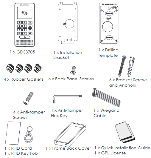
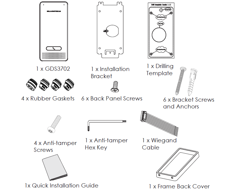
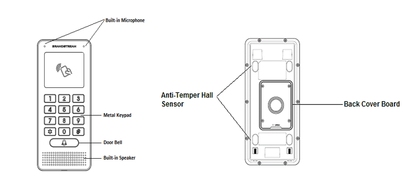
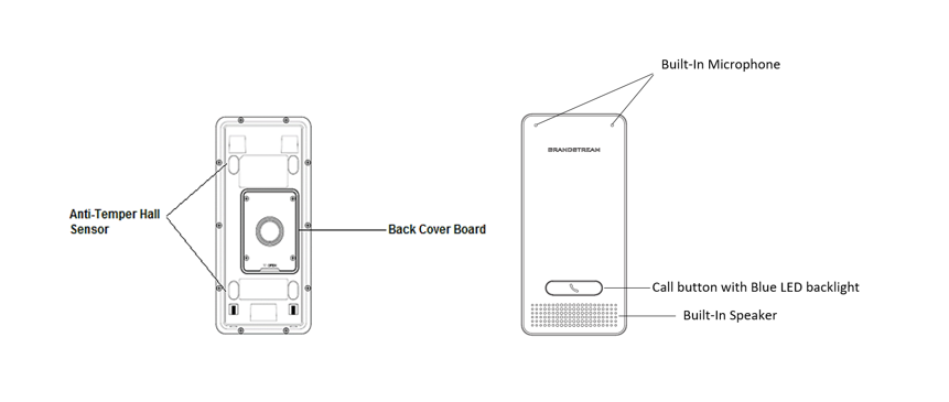
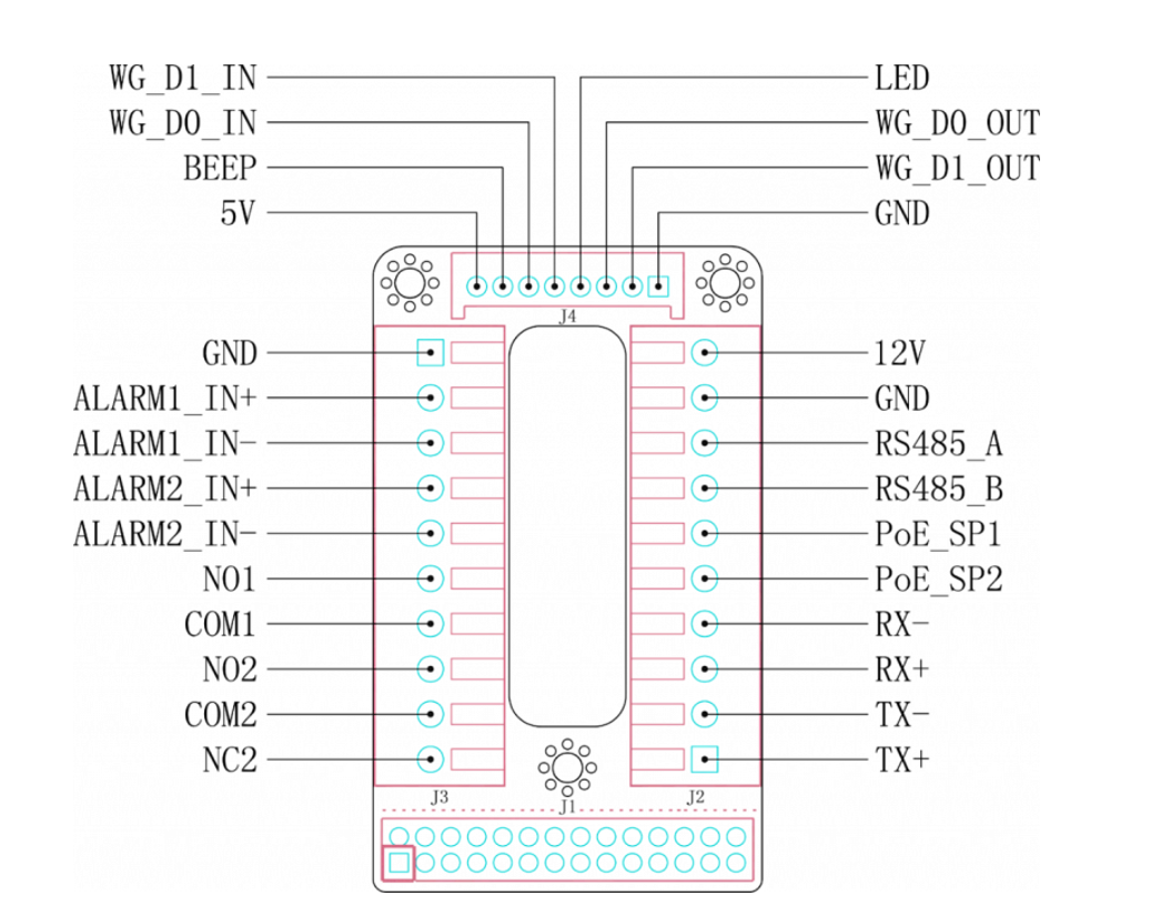
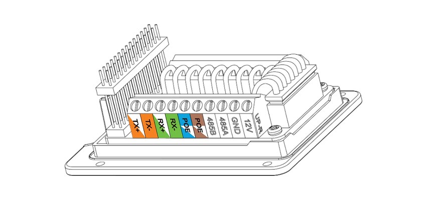

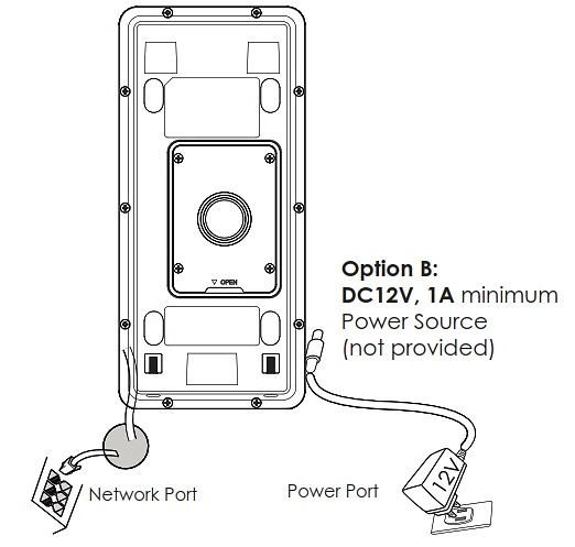


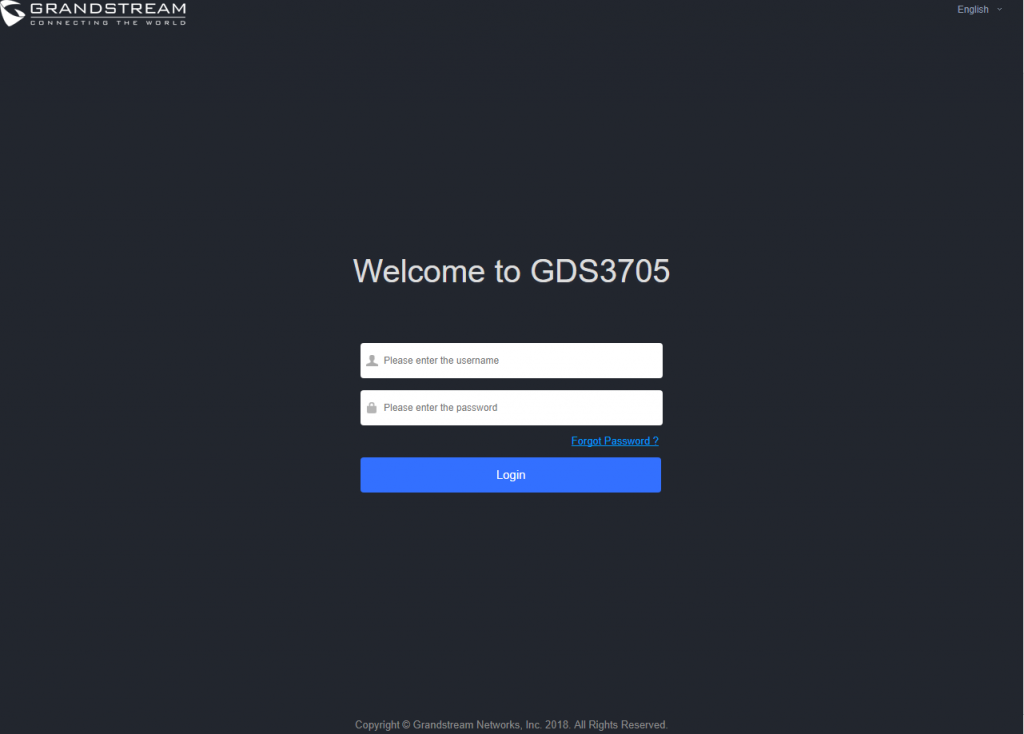

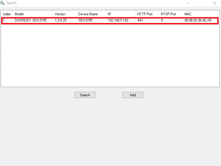


 button to start device detection


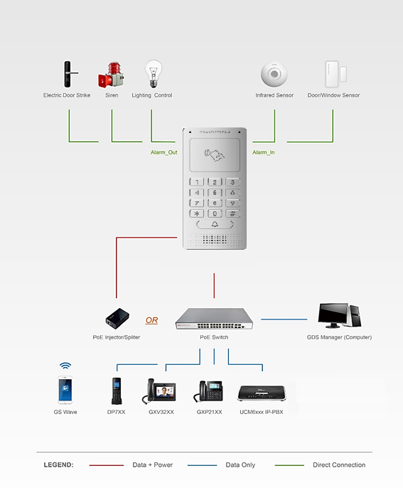
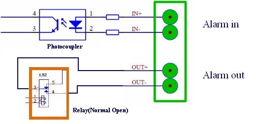
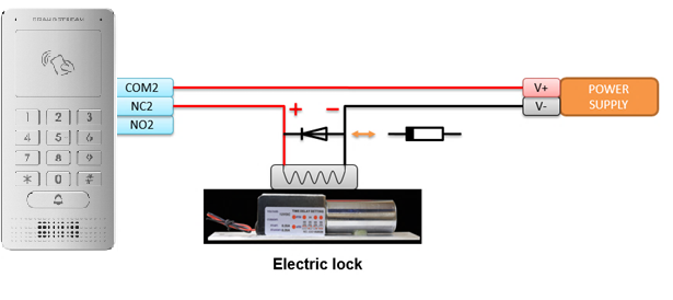
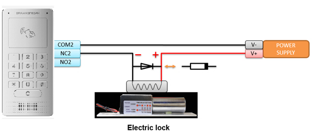
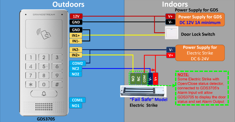

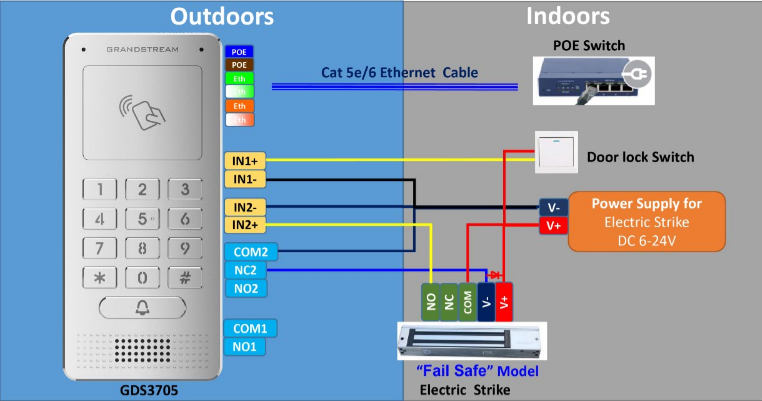
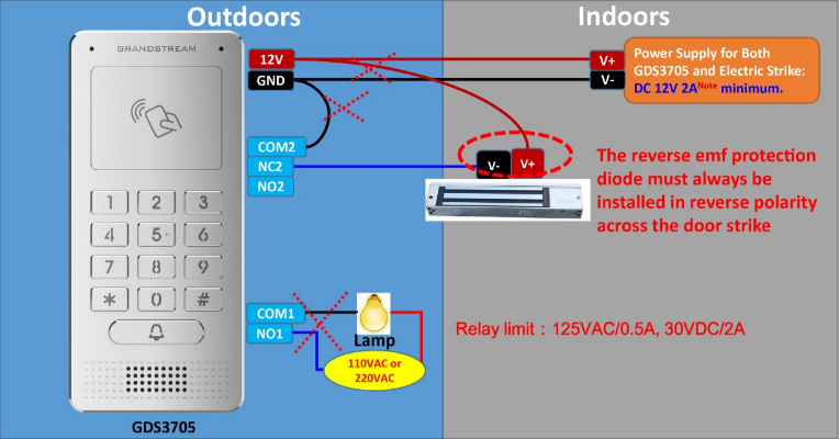
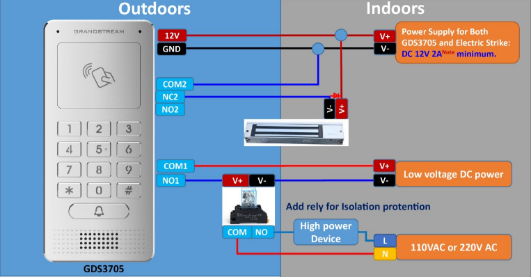

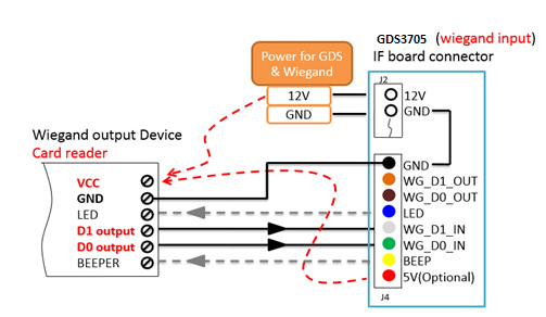
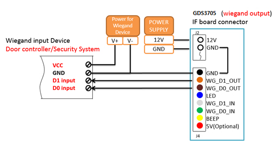
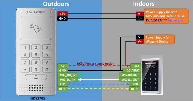


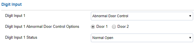
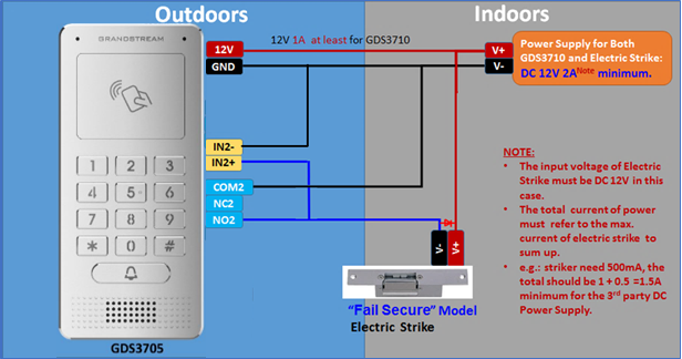
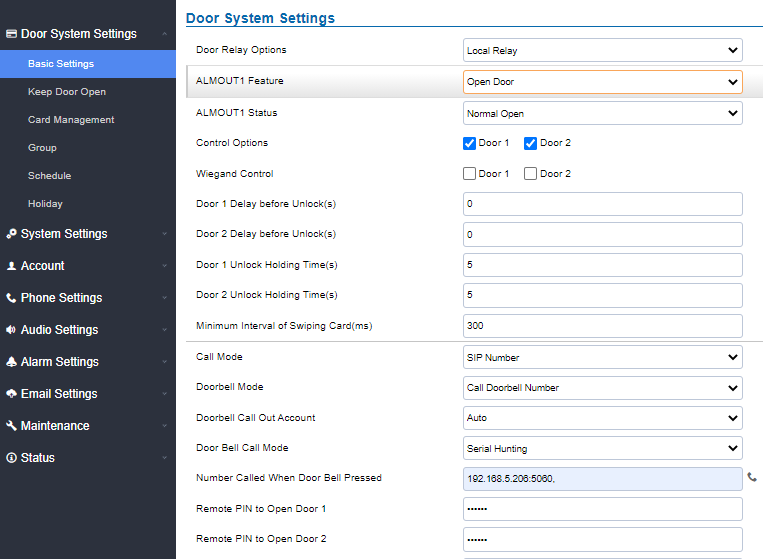
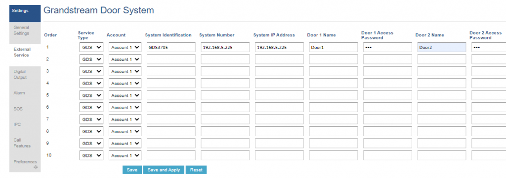
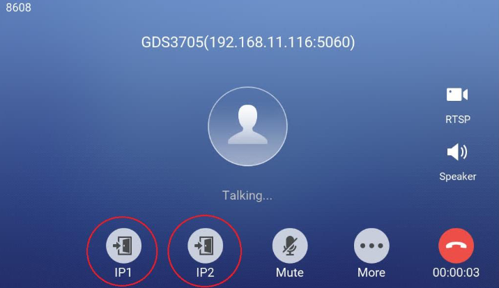
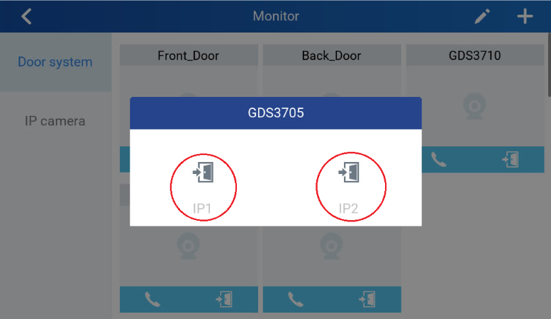
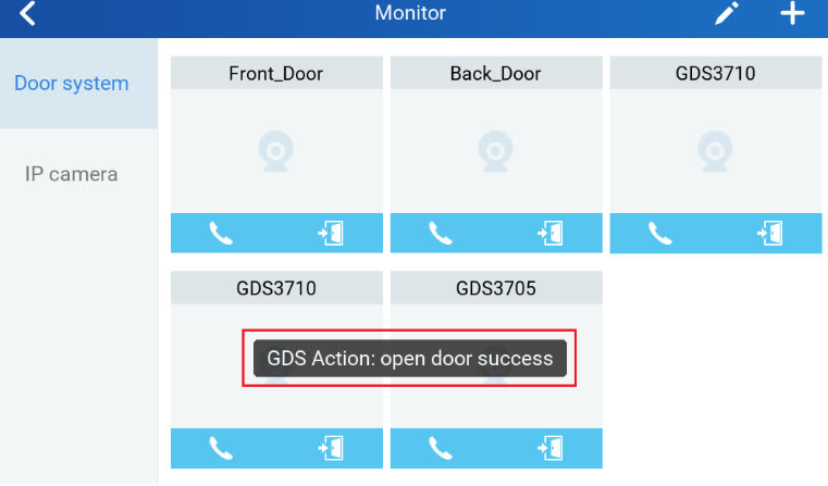
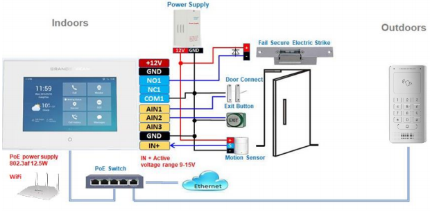
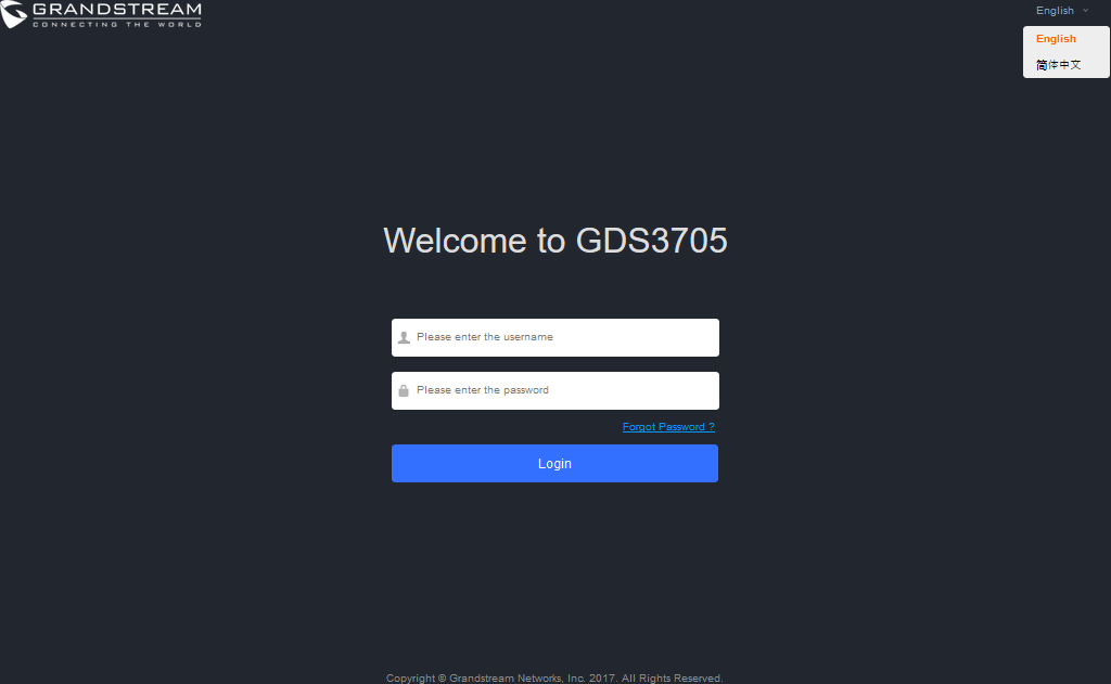

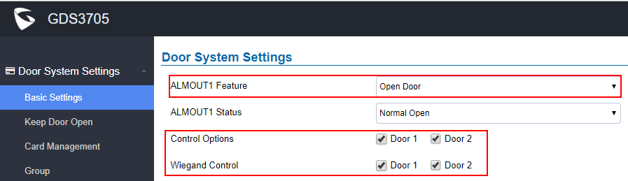
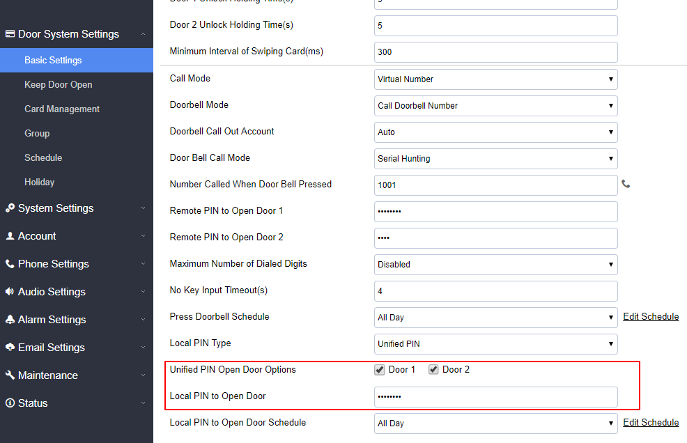
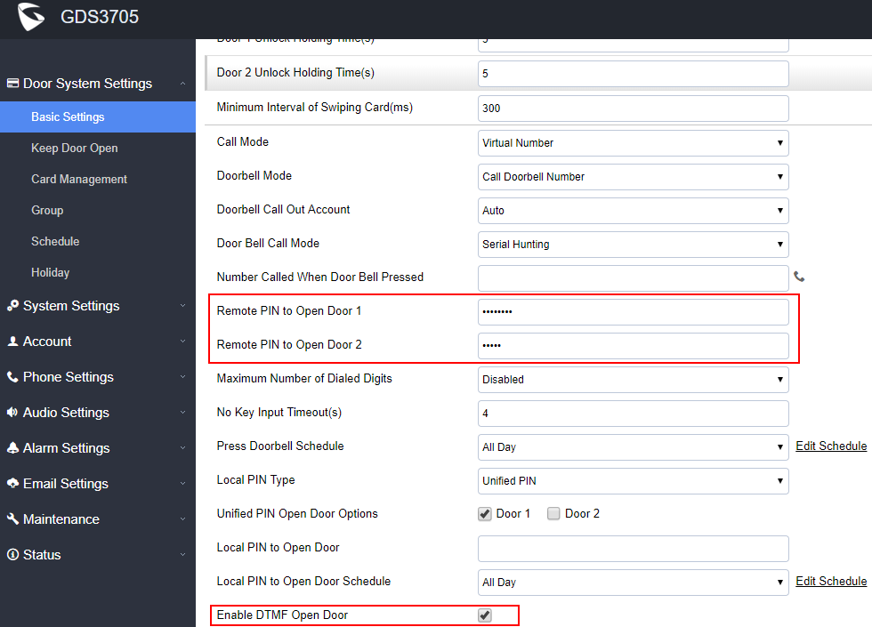
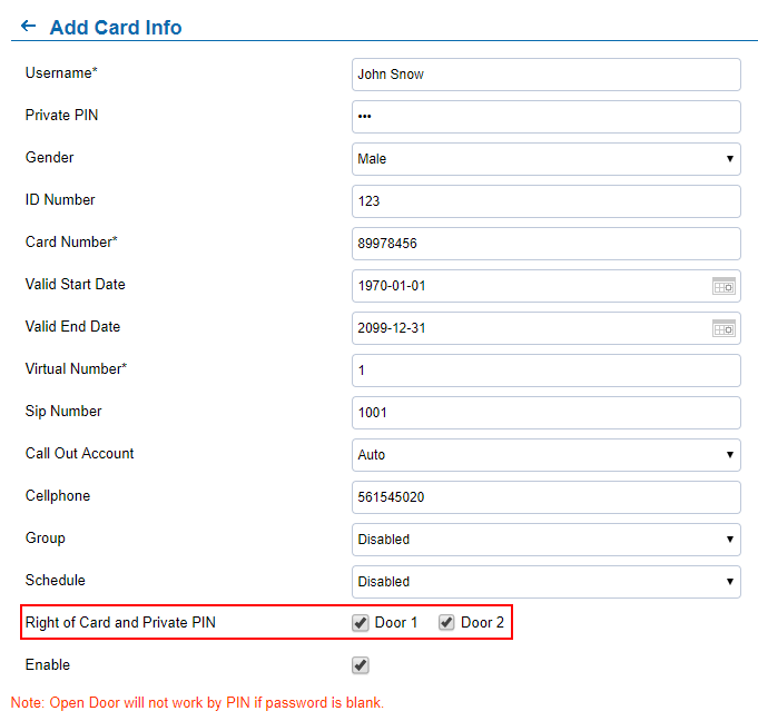
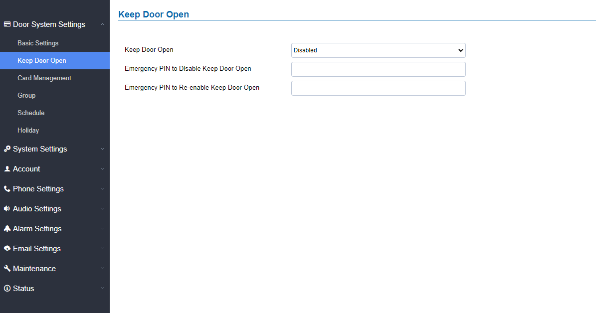
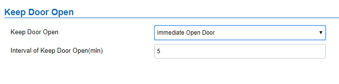
 to open the door immediately. The default value is 5.
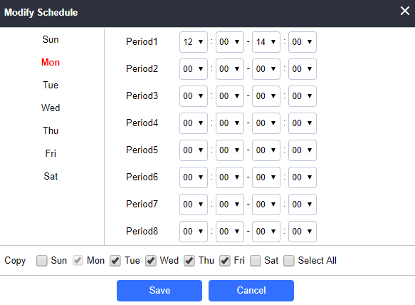

 or
or  to
to  to search for an entry on the Cards list.
 , the following page will pop up.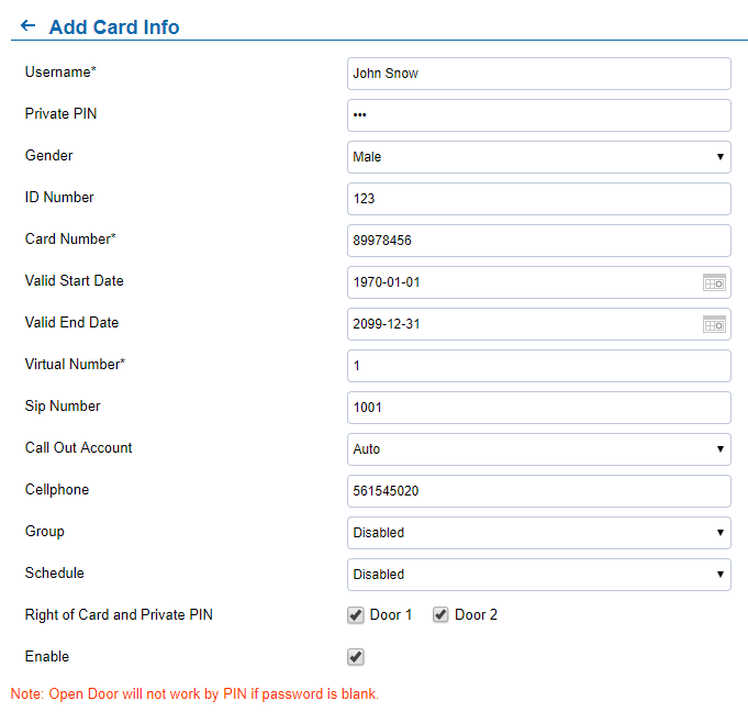




 to create new groups or
  to edit existing groups, or
  to delete the group.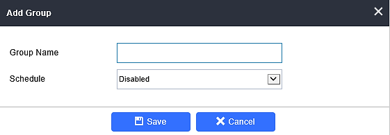
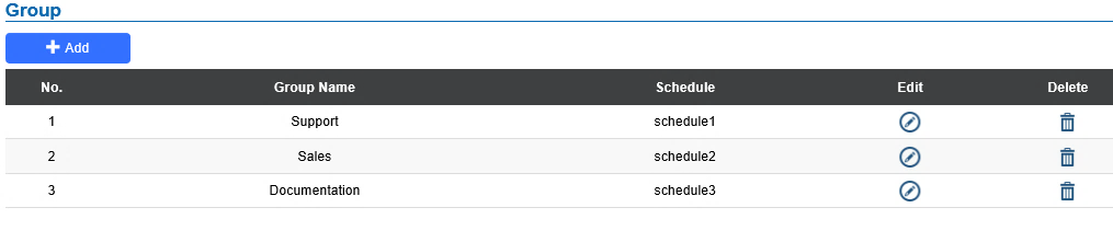
 to edit a schedule or
 for schedule details.

 to edit the holidays or
  for holiday details.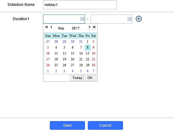
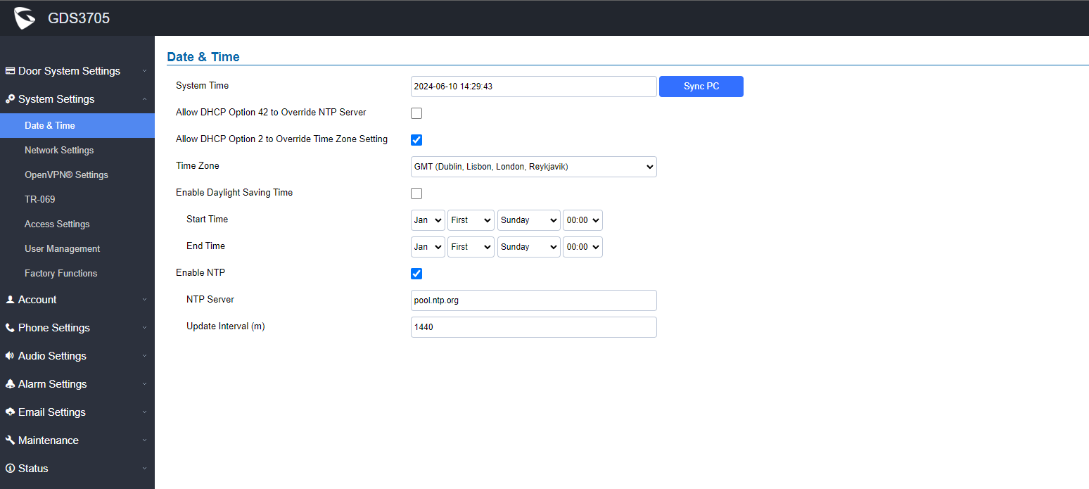
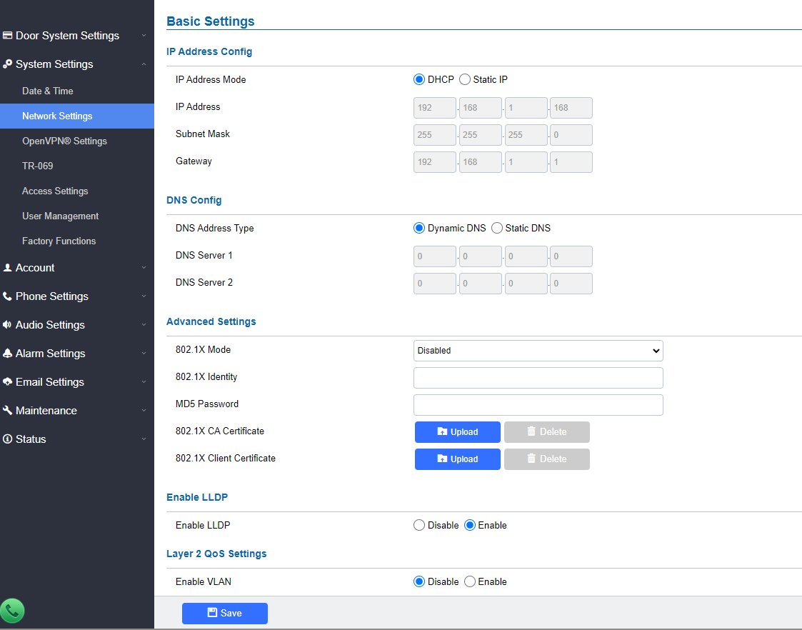
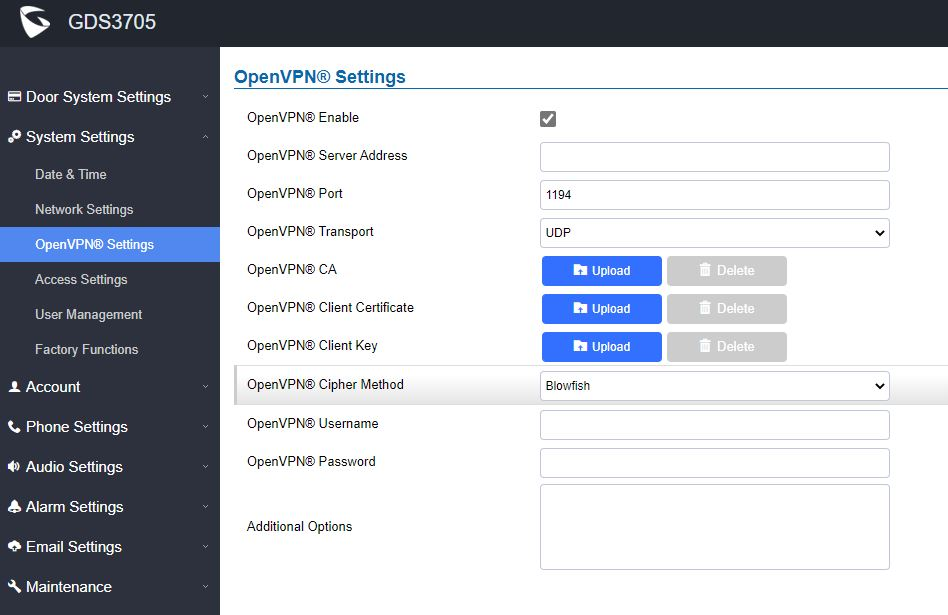
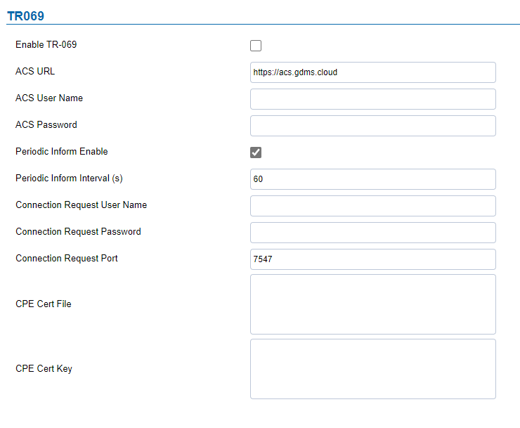
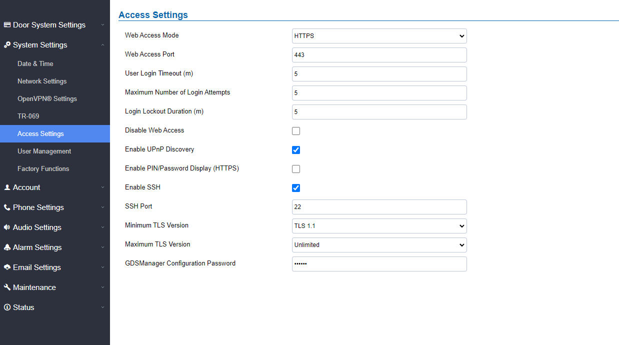
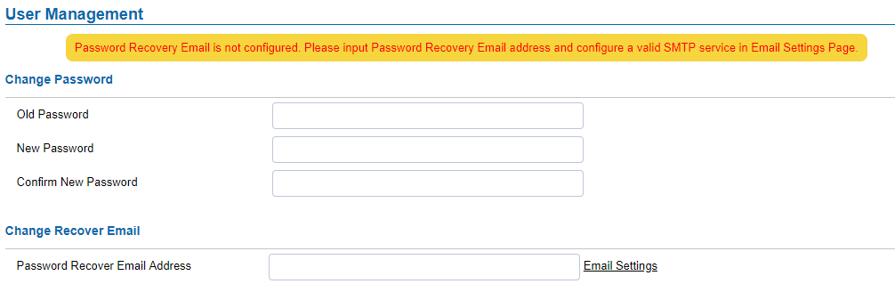

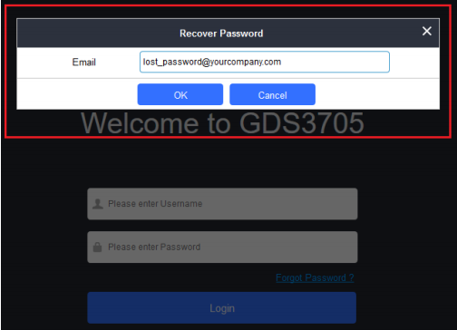

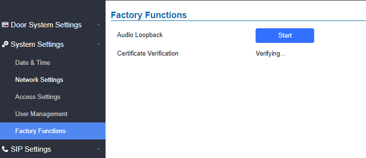

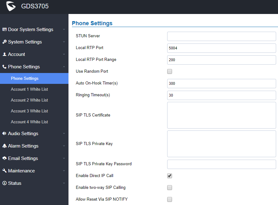
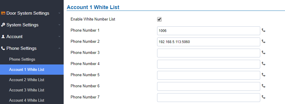




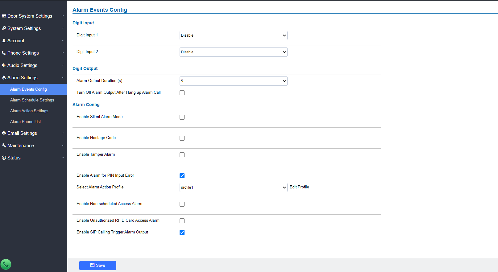
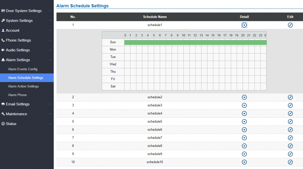
 button. Usually, the 24-hour span is 00:00 ~ 23:59, which is 24 24-hour format.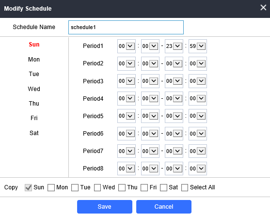
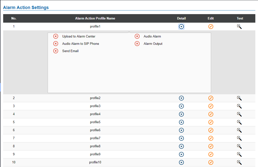
 button, the following window will pop up.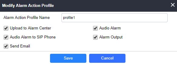
 button and the GDS will initiate all actions specified in the selected alarm profile.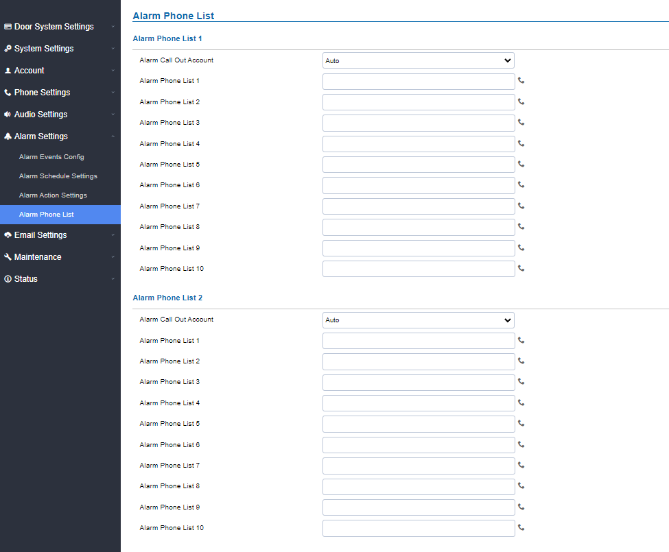
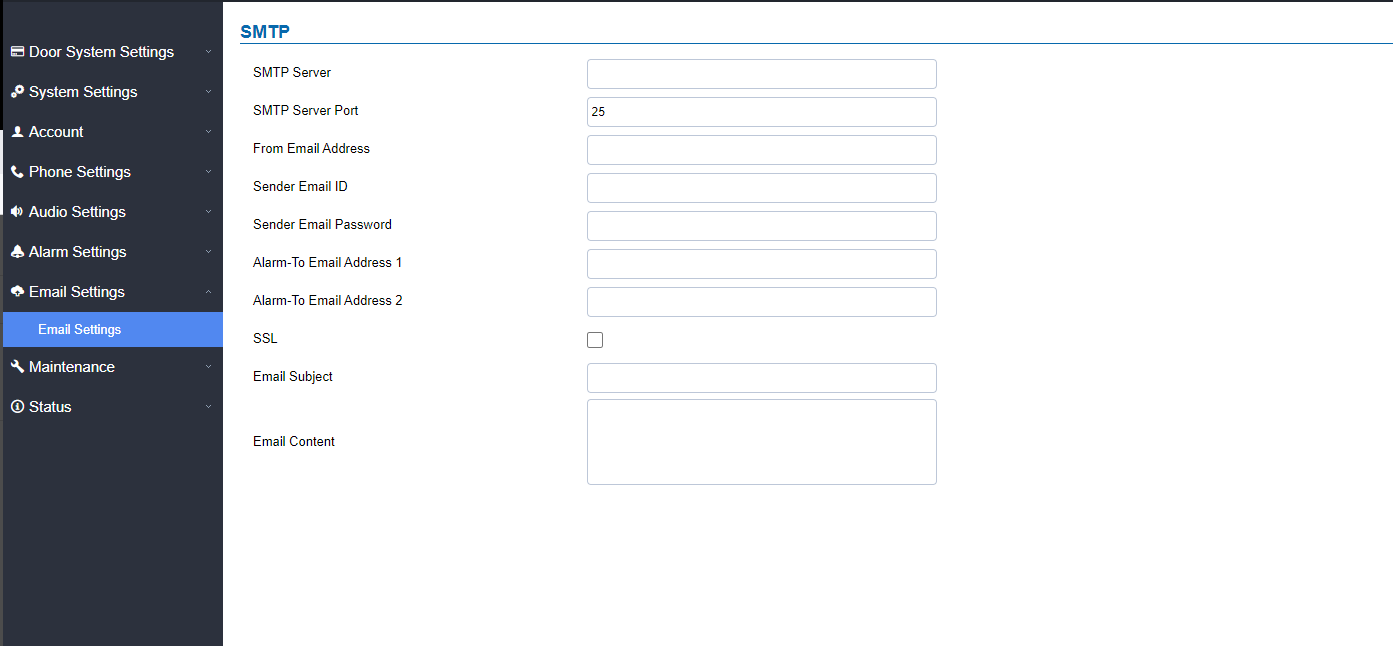
 .
.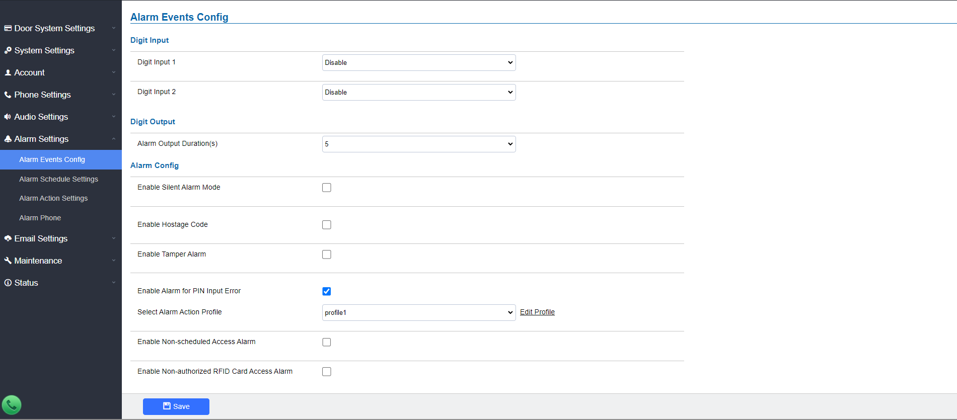
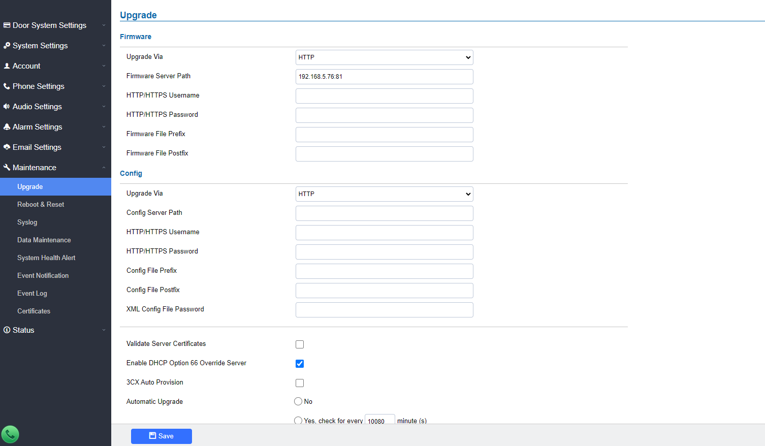
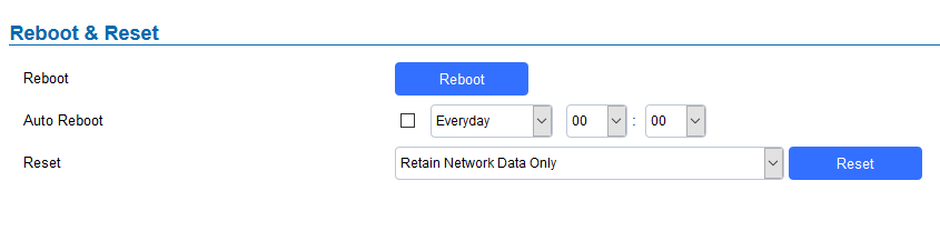
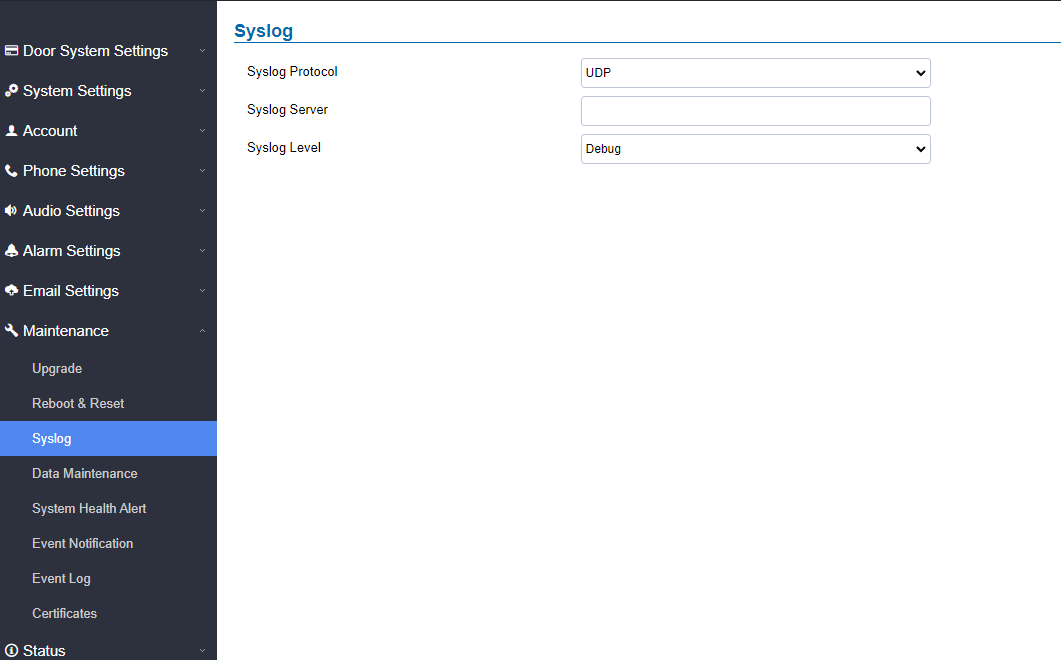
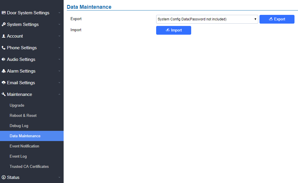
 to save the GDS370x configuration in a predefined directory.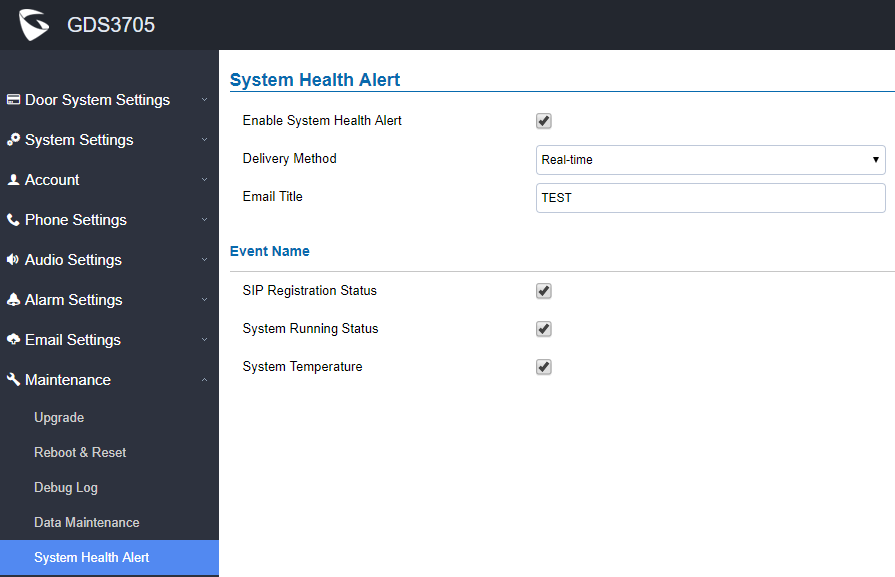

 to display the records.

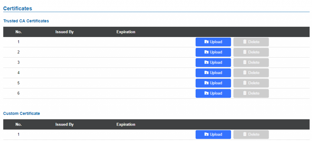
 button to upload a file, and some related information to the uploaded file will be displayed, such as “Issued by” and “Expiration date”.
 to delete one of the files.
 button to upload a file, and some related information to the uploaded file will be displayed, such as “Issued by” and “Expiration date”.
 to delete one of the files.