


Overview
The GCC6020 Series is a powerful all-in-one platform that integrates unified communications, networking, and advanced security features into a single device. Designed for small-to-medium-sized businesses, this series combines the capabilities of four distinct products: a high-performance VPN router, a next-generation firewall, a full-featured IP PBX system, and an enterprise-grade network switch.
These state-of-the-art devices enable the creation and centralized management of wired, wireless, and VPN networks, while providing robust security through built-in firewall functions, DPI, IDS/IPS, and encrypted traffic protection. The embedded IP PBX platform supports both voice and video communications with advanced collaboration tools, making it ideal for modern business environments.
The GCC6020 Series simplifies deployment and ongoing administration by offering unified control of Grandstream Wi-Fi access points, network switches, IP phones, and other endpoints. It supports a wide range of management methods, including Grandstream Device Management System (GDMS), mobile app, local Web UI, CLI, and SSH console.
With support for fast provisioning, centralized monitoring, and cloud-based control, the GCC6020 and GCC6021 models make it easier and more cost-effective to deploy secure, scalable, and fully integrated communication networks.
Package Contents
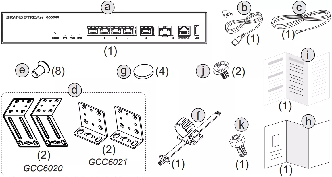
The GCC6020/GCC6021 package includes the following components:
Label | Quantity | Item |
a | 1× | Main Unit (GCC6020 or GCC6021) |
b | 1× | Power Cable |
c | 1× | Grounding Cable |
d | 2× | Rack Mount Brackets (model-specific) |
e | 8× | Rack Mounting Screws |
f | 1× | Power Cord Anti-Trip |
g | 4× | Rubber Feet |
h | 1× | Regulatory Information |
i | 1× | Quick Installation Guide |
j | 2× | M.2 SSD Screws (top) |
k | 1× | M.2 SSD Securing Screw (bottom) |
Package Contents
Hardware Overview
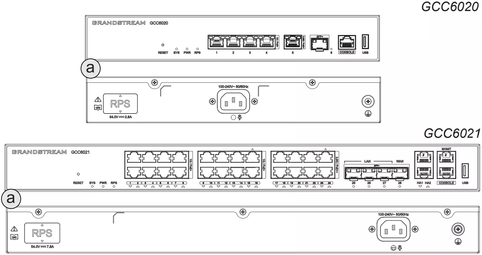
The GCC6020 and GCC6021 feature front and rear panels with multiple Ethernet, SFP, USB, and management ports. The exact port layout varies depending on the model.
Each unit includes a standard AC power input and a Redundant Power Supply (RPS) port on the back panel. LED indicators on the front help monitor power, connectivity, and system status.
Powering the Device
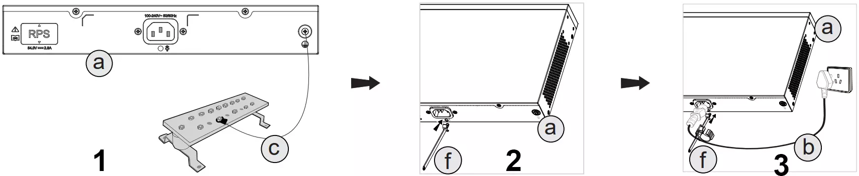
Follow the steps below to properly power the GCC6020/GCC6021:
- Ground the Device
Attach the grounding cable (c) to the grounding point (a) on the rear panel to prevent electrical surges. - Secure the Power Cable
Install the power cord Anti-Trip (f) onto the power socket. This helps prevent accidental unplugging or cable strain. - Connect the Power Cable
Plug the power cable (b) into the device, then wrap the Power Cord Anti-Trip (f) around it as shown before connecting to a power outlet.
Rack Mount Installation
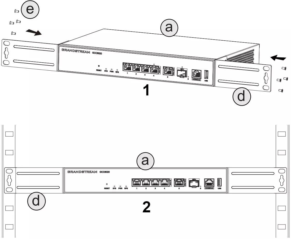
To mount the device into a standard 19” rack:
- Attach the Rack Brackets
Secure the provided rack mount brackets (d) to both sides of the device (a) using the included screws (e). - Install the Unit into the Rack
Carefully align and slide the device into the rack, then secure the brackets to the rack frame.
Installing the M.2 SSD
- Access the SSD Slot: Flip the device upside down to locate the SSD compartment (a). Remove the bottom SSD cover by unscrewing the pre-installed screw.
- Install the SSD: Secure the standoff screw (k) in the appropriate mounting position. Insert the M.2 SSD module into the slot at an angle, then press it down flat. Fasten it using the hold-down screw (j) to secure the SSD in place.
- Close the SSD Compartment: Reattach the metal cover and tighten the original screw to finish the installation.

Refer to the tables below for detailed SSD hardware requirements and compatible models.
SSD Hardware Requirements | ||
Interface Type | M.2 PCIe (NVMe protocol) | |
Interface Specifications | PCIe 3.0 x2 | |
Theoretical Maximum Bandwidth | 1.97 GB/s | |
Compatibility Notes |
| |
Size | 2280 (80mm × 22mm), mainstream and recommended 2260 (60mm × 22mm) 2240 (40mm × 22mm) | |
Thickness | 2–4mm, compliant with standard M.2 slot device specifications | |
Maximum Capacity | The SSD interface has no capacity limit, the capacity depends on the SSD inserted. | |
Recommended SSD Types and Performance Requirements |
| |
Work Environment |
| |
Precautions |
| |
The following SSD models have passed compatibility testing. | ||
Brand | Model | Memory Size |
Colorful Rainbow | CN600 256GB HT4E1C | 256GB |
SanDisk | SDSSDA3N-1T00 | 1TB |
Samsung | MZ-V8V250 | 250GB |
Samsung | MZ-V7S500 | 500GB |
Kingston | SNV2S/500GCN | 500GB |
SSD hardware requirements and compatible models.
Connecting to GCC602x
- Connect the WAN port (marked with △) to your internet uplink such as an optical modem, router, or ISP-provided gateway.
- Connect a PC or laptop to one of the LAN ports on the GCC602x.
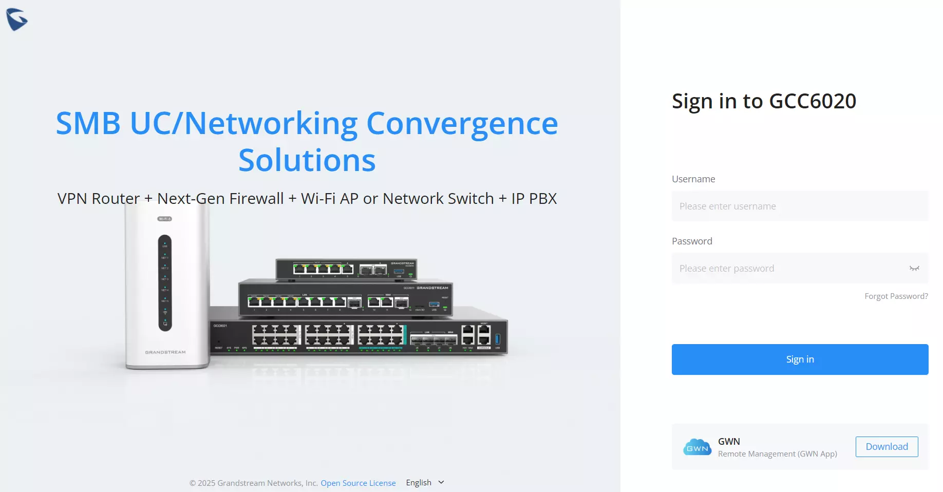
- Open a web browser and access the default gateway:
http://192.168.80.1orgcc.grandstream.com
Safety and Precautions
Refer to online documents and FAQ for more detailed information:
https://www.grandstream.com/our-products